Trans. Nonferrous Met. Soc. China 23(2013) 781-787
Finite element simulation of ball spinning of NiTi shape memory alloy tube based on variable temperature field
Shu-yong JIANG1, Yan-qiu ZHANG1, Ya-nan ZHAO1, Ming TANG1, Chun-feng LI2
1. Industrial Training Centre, Harbin Engineering University, Harbin 150001, China;
2. School of Materials Science and Engineering, Harbin Institute of Technology, Harbin 150001, China
Received 28 December 2011; accepted 27 May 2012
Abstract: As a new attempt, ball spinning was used to manufacture the nickel-titanium shape memory alloy (NiTi SMA) tube at elevated temperature. The NiTi bar with a nominal composition of Ni50.9Ti49.1 (mole fraction, %) was solution treated and was used as the original tube blank for ball spinning. Based on the variable temperature field and the constitutive equation, rigid-viscoplastic finite element method (FEM) was applied in order to simulate the ball spinning of NiTi SMA tube. The temperature field, the stress field, the strain field and the load prediction were obtained by means of FEM. FEM results reveal that there is a temperature increase of about 160 °C in the principal deformation zone of the spun part. It can be found from the stress fields and the strain fields that the outer wall of NiTi SMA tube is easier to meet the plastic yield criterion than the inner wall, and the plastic deformation zone is caused to be in a three-dimensional compressive stress state. The radial strain and the tangential strain are characterized by the compressive strain, while the axial strain belongs to the tensile strain. The variation of spinning loads with the progression of the ball is of great importance in predicting the stable flow of the spun part.
Key words: NiTi alloy; NiTi tube; shape memory alloy; finite element method; ball spinning
1 Introduction
Nickel-titanium shape memory alloy (NiTi SMA) is widely used in engineering fields because of its shape memory effect as well as superelasticity. Shape memory effect of NiTi SMA refers to its ability to remember the shape at a certain state when being heated to the temperature above the austenite finish temperature (Af) after undergoing a certain deformation in the martensitic phase. Superelasticity of NiTi SMA refers to its nonlinear recoverable deformation behavior at the temperatures above Af. Superelasticity is attributed to the stress-induced martensitic transformation by loading as well as the spontaneous reverse martensitic transformation after unloading [1].
NiTi SMA tube has been one of the best candidates for the biomedical instruments so far because it possesses perfect shape memory effect, good corrosion resistance, high plateau stress, ultimate tensile strength, high fatigue life and outstanding superelastic behavior at or around the body temperature [2-6]. The thin-walled superelastic NiTi SMA tube is typically used for endovascular stents [7].
However, NiTi SMA tube is difficult to process because of high strain hardening and large elastic resilience [8]. Plastic working plays a significant role in fabricating NiTi SMA tube. Furthermore, plastic working has a predominant influence on shape memory effect as well as superelasticity of NiTi SMA tube. So far, the NiTi SMA tube has been mainly manufactured by means of drawing [9,10]. In addition, the extrusion process was also used to manufacture the NiTi SMA tube [11].
As a locally and successively plastic deformation process, ball spinning is the best candidate for manufacturing the thin-walled tube with high precision and high strength [12-15]. As compared to the drawing and the extrusion, ball spinning makes a more great contribution to manufacturing the thin-walled NiTi SMA tube. In the present study, ball spinning is used to form the thin-walled NiTi SMA tube at elevated temperature. Rigid viscoplastic finite element method (FEM) based on the variable temperature field as well as the constitutive equation is investigated in order to understand the deformation mechanism with respect to ball spinning of NiTi SMA tube.
2 Experimental
2.1 Spinning mode
The backward ball spinning was adopted in order to enhance the plasticity of the metal material. In the course of backward ball spinning, the spinning head was fixed in the chuck of the spinning lathe and turned with the principal axis of the spinning lathe. At the same time, the tubular blank was mounted on the mandrel and fed with the mandrel along the axial direction.
As shown in Fig. 1, the spinning tools were made up of the mandrel, the stripper and the spinning head which consists of die ring, balls, bolt and stop plate. The mandrel was made from high temperature alloy steel.
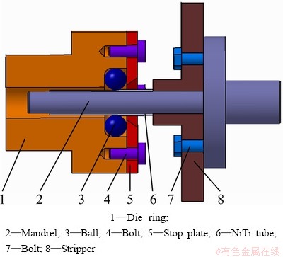
Fig. 1 Schematic diagram of spinning tools
2.2 Spinning material
The as-received NiTi alloy with a nominal composition of Ni50.9Ti49.1 (mole fraction, %) was prepared by vacuum induction melting method, and was then rolled at 800 °C, and finally was drawn to the NiTi bar with the diameter of 12 mm at 400 °C. The NiTi bar was subjected to a solution treatment which referred to annealing at 850 °C for 2 h followed by quenching in ice water. The solution-treated NiTi bar was made into the NiTi tube blank with the inner diameter of 10 mm and the wall thickness of 1 mm. Figure 2 indicates the microstructures of the original NiTi tube blank. It can be observed from the optical microstructures in Fig. 2(a) that NiTi tube blank consists of the equiaxed grains. Furthermore, transmission electron microscopy (TEM) photograph in Fig. 2(b) and the selected area electron diffraction (SAED) pattern in Figs. 2(c) and (d) indicate that NiTi tube blank is composed of B2 austenite structure and a small amount of TiC phase. The spun NiTi alloy tube is shown in Fig. 3.
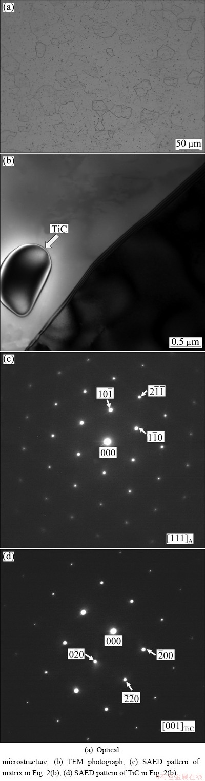
Fig. 2 Microstructures of NiTi alloy tube blank
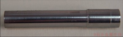
Fig. 3 Spun NiTi alloy tube
2.3 Spinning parameters
The involved process parameters during backward ball spinning were as follows. The feed ratio of the balls was 0.8 mm/r and the diameter of the balls was 10 mm. The wall thickness reduction per pass was 0.3 mm. The number of the balls can be calculated as 6 according to Ref. [16]. The initial temperature of the NiTi tube blank was heated to 750 °C.
3 Finite element model
3.1 Fundamentals of rigid-viscoplastic FEM
Rigid-viscoplastic FEM is based on the variational principles. The functional π is established as follows according to the plastic deformation body by adding the incompressibility condition.
 (1)
(1)
where V and S are the volume and the surface area of the plastic deformation body, respectively; Fi is the surface tractions; ui is the velocity field;  is the volume strain rate; α is the penalty factor, which is a very large positive constant and in general ranges from 105 to 107;
  is the work function and is expressed as follows.
 (2)
(2)
The actual solution makes the first-order variation of the functional π vanish, namely
 (3)
(3)
Equation (3) is the basic equation for the finite element discretization.
3.2 Fundamentals of heat conduction FEM
During plastic deformation of metal material, according to heat transfer in the rigid-viscoplastic flow of metal material, heat by plastic deformation and heat by friction, the three-dimensional heat transfer differential equation based on conservation of energy is expressed by
 (4)
(4)
where λ is the coefficient of heat conductivity; ρ is the density; c is the specific heat capacity; t is the time; T is the thermodynamic temperature;  is the heat quantity per volume derived from plastic deformation work and is expressed as follows:
 (5)
(5)
where β represents the heat efficiency with respect to transformation from the plastic deformation energy to the heat energy and ranges from 0.9 to 0.95.
According to the initial temperature condition and boundary condition, the temperature field can be solved by finite element discretization of Eq. (4) at time domain and at spatial domain.
3.3 Constitutive equation of NiTi alloy
According to the true stress―strain curves of NiTi alloy under compression at the strain rates ranging from 0.001 s-1 to 1 s-1 and at the temperatures ranging from 600 °C to 1000 °C, the constitutive equation of NiTi alloy is established as follows.

 (6)
(6)
The detailed description with respect to establishing the constitutive equation of NiTi alloy shall be published in another literature. Equation (6) is used as the material model for finite element simulation.
3.4 Finite element model
DEFORM3D finite element code is used to simulate backward ball spinning of NiTi alloy tube. Finite element model of backward ball spinning of NiTi alloy tube is shown in Fig. 4, where the six balls are adopted according to the actual spinning experiment. The dimensions of the cross-section of the mandrel are identical to those in the experiment. The balls have a feed movement along the axial direction as well as a revolution movement along the circumferential direction, but the mandrel is constrained. The tube blank belongs to the free surface at the entrance end of the balls, while the tube blank possesses the constrained surface at the exit end of the balls. The feed ratio of the balls is 0.8 mm/r, and the diameter of balls is 10 mm. The tubular blank with a length of 15 mm, an inner diameter of 10 mm and a wall thickness of 1 mm is used as finite element model. The wall thickness reduction per pass is 0.3 mm. The stroke of the ball is determined as 7.8 mm. The NiTi tube blank and the mandrel are heated at the same time, so the initial temperatures of the NiTi tube blank, the mandrel and the balls are determined as 750, 600 and 20 °C, respectively.
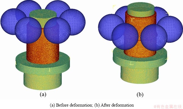
Fig. 4 Finite element model of ball spinning
4 Results and discussion
4.1 Temperature field
Figure 5 illustrates the temperature fields of the spun part, the mandrel and the ball based on finite element simulation of ball spinning of NiTi alloy tube, respectively. It can be seen from Fig. 5(a) that the highest temperature is able to achieve to 910 °C in the principal deformation zone between the ball and the spun part, which is attributed to the generation of heat resulting from plastic deformation work. As compared to the initial temperature of the NiTi alloy tube blank at the beginning of spinning, the temperature rise in the principal deformation zone is about 160 °C. The excessive temperature rise has an adverse influence on the ball spinning of the NiTi alloy tube since too high temperature will lead to severe oxidization as well as coarse dynamic recrystallized grains of the NiTi alloy tube. Therefore, it is necessary to avoid the excessively high temperature rise during the ball spinning of NiTi alloy tube. It can be found from Fig. 5(b) that there is a slight temperature increase in the contact region of the mandrel with the NiTi tube blank, and the temperature field distributes regularly and the temperature decreases gradually toward the fixed end of the mandrel. The lower temperature rise in the mandrel does not have an effect on the strength and the rigidity of the mandrel. It can be seen from Fig. 5(c) that there is a temperature increase of about 300 °C in the center of the surface of the ball on which the ball contacts the spun part. Furthermore, the temperature field distributes uniformly around the center of the surface of the ball and the temperature decreases outward the center of the surface of the ball.
4.2 Stress field
Figure 6 indicates the stress field of the spun part derived from finite element simulation. It can be seen from the effective stress distribution in Fig. 6 that the effective stress decreases gradually from the outer wall to the inner wall of the spun part, which reveals that the outer wall of the spun part is more subjected to plastic yield criterion. Therefore, it is necessary to select the tube blank with the appropriate wall thickness in the case of a given ball diameter. The larger wall thickness will lead to the occurrence of the plastic deformation on the outer wall rather than the inner wall of the spun part, which has an adverse influence on the ball spinning process of the NiTi alloy tube. In addition, it can be found from the radial stress field, the tangential stress field and the axial stress field in Fig. 6 that the radial stress, the tangential stress and the axial stress in the plastic deformation zone exhibit the compressive stress. Therefore, the plastic deformation zone during the ball spinning of NiTi alloy tube is caused to be in a three-dimensional compressive stress state, which is of great importance in enhancing the plasticity of the NiTi alloy.
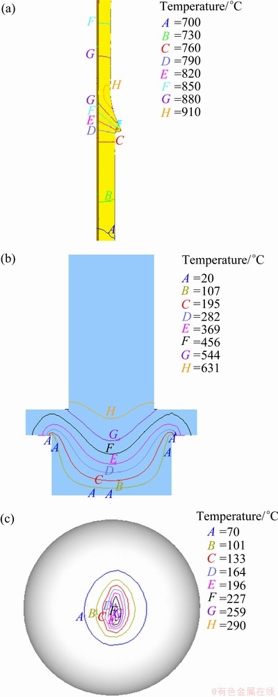
Fig. 5 Temperature fields of spun part (a), mandrel (b) and ball (c)
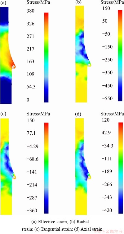
Fig. 6 Stress field of spun part
4.3 Strain field
Figure 7 shows the strain field of the spun part derived from finite element simulation. It can be found from the effective strain distribution in Fig. 7 that the effective strain decreases gradually from the outer wall to the inner wall of the spun part, which reveals that the larger plastic deformation appears on the outer surface of the spun part, while the less plastic deformation arises on the inner surface of the spun part. It can be found from the radial strain field, the tangential strain field and the axial strain field in the plastic deformation zone in Fig. 7 that the radial strain and the tangential strain are characterized by the compressive strain, while the axial strain belongs to the tensile strain. The compressive strain in the radial direction and the tensile strain in the axial direction contribute to the plastic flow of the metal material. However, the compressive strain in the tangential direction will lead to the tendency of the spun part toward the reduction of the inner diameter, which has an adverse influence on the quality of the spun part.
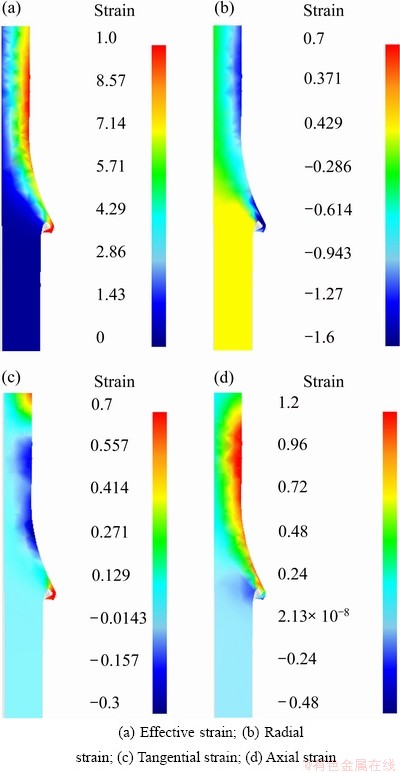
Fig. 7 Strain field of spun part
4.4 Load prediction
The spinning force during ball spinning of the NiTi alloy tube can be divided into three spinning force components, namely the radial spinning force component, the tangential spinning force component and the axial spinning force component. Figure 8 indicates the spinning load prediction curves obtained by finite element simulation. It can be observed from Fig. 8 that the three spinning force components increase with the progression of the stroke of the ball at the initial stage and exhibit the periodical variation at the subsequent stage. The above phenomenon reveals that the metal material exhibits the unstable flow at the initial stage during the ball spinning of NiTi alloy tube, while the metal material exhibits the stable flow at the subsequent stage during the ball spinning of NiTi alloy tube.

Fig. 8 Prediction of spinning load by FEM
5 Conclusions
1) Finite element simulation result reveals that there is a temperature rise of about 160 °C in the principal deformation zone of the NiTi alloy tube and there is a temperature increase of about 300 °C in the center of the surface of the ball on which the ball contacts the spun part.
2) It can be found from the stress fields derived from finite element simulation that the outer wall of the NiTi alloy tube is easier to meet the plastic yield criterion than the inner wall, and the plastic deformation zone is caused to be in a three-dimensional compressive stress state, which contributes to enhancing the plasticity of the NiTi alloy.
3) Finite element simulation results reveal that the compressive strain in the radial direction and the tensile strain in the axial direction contribute to the plastic flow of the metal material, but the compressive strain in the tangential direction shall lead to the tendency of the spun part toward the reduction of the inner diameter.
4) The variation of the spinning loads with the progression of the stroke of the ball reveals that the metal material exhibits the unstable flow at the initial stage of spinning, but exhibits the stable flow at the subsequent stage.
References
[1] OTUKA K, REN X. Physical metallurgy of Ti-Ni-based shape memory alloys [J]. Progress in Materials Science, 2005, 50(5): 511-678.
[2] NG K L, SUN Q P. Stress-induced phase transformation and detwinning in NiTi polycrystalline shape memory alloy tubes [J]. Mechanics of Material, 2006, 38(1-2): 41-56.
[3] LI Z Q, SUN Q P. The initiation and growth of macroscopic martensite band in nano-grained NiTi microtube under tension [J]. International Journal of Plasticity, 2002, 18(11): 1481-1498.
[4] HE Y J, SUN Q P. Scaling relationship on macroscopic helical domains in NiTi tubes [J]. International Journal of Solids and Structures, 2009, 46(24): 4242-4251.
[5] WANG Y F, YUE Z F, WANG J. Experimental and numerical study of the superelastic behaviour on NiTi thin-walled tube under biaxial loading [J]. Computational Materials Science, 2007, 40(2): 246-254.
[6] MAO S C, LUO J F, ZHANG Z, WU M H, LIU Y, HAN X D. EBSD studies of the stress-induced B2-B19/ martensitic transformation in NiTi tubes under uniaxial tension and compression [J]. Acta Materialia, 2010, 58(9): 3357-3366.
[7] ROBERTSON S W, RITCHIE R O. In vitro fatigue-crack growth and fracture toughness behavior of thin-walled superelastic Nitinol tube for endovascular stents: A basis for defining the effect of crack-like defects [J]. Biomaterials, 2007, 28(4): 700-709.
[8] WU M H. Fabrication of Nitinol materials and components [J]. Material Science Forum, 2001, 394-395: 285-292.
[9] YOSHIDA K, WATANABE M, ISHIKAWA H. Drawing of Ni-Ti shape-memory-alloy fine tubes used in medical tests [J]. Journal of Materials Processing Technology, 2001, 118(1-3): 251-255.
[10] YOSHIDA K, FURUYA H. Mandral drawing and plug drawing of shape-memory-alloy fine tubes used in catheters and stents [J]. Journal of Materials Processing Technology, 2004, 153-154: 145-150.
[11]  K. Extrusion of nickel-titanium alloys Nitinol to hollow shapes [J]. Journal of Materials Processing Technology, 2001, 111(1-3): 122-126.
[12] JIANG Shu-yong, LI Ping, XUE Ke-min. Application of BPANN in spinning deformation of thin-walled tubular parts with longitudinal inner ribs [J]. Journal of Central South University of Technology, 2004, 11(1): 27-30.
[13] JIANG Shu-yong, XUE Ke-min, ZONG Ying-ying, YU Lin. Process factors influencing spinning deformation of thin-walled tubular part with longitudinal inner ribs [J]. Transactions of Nonferrous Metals Society of China, 2004, 14(4): 702-707.
[14] JIANG Shu-yong, REN Zheng-yi, WU Bin, WU Gui-xiang. General issues of FEM in backward ball spinning of thin-walled tubular part with longitudinal inner ribs [J]. Transactions of Nonferrous Metals Society of China, 2007, 17(4): 793-798.
[15] JIANG Shu-yong, ZHENG Yu-feng, REN Zheng-yi, LI Chun-feng. Multi-pass spinning of thin-walled tubular part with longitudinal inner ribs [J]. Transactions of Nonferrous Metals Society of China, 2009, 19(1): 215-221.
[16] JIANG Shu-yong, REN Zheng-yi, LI Chun-feng, XUE Ke-min. Role of ball size in backward ball spinning of thin-walled tubular part with longitudinal inner ribs [J]. Journal of Materials Processing Technology, 2009, 209(4): 2167-2174.
基于变温度场的镍钛形状记忆合金管滚珠旋压有限元模拟
江树勇1, 张艳秋1, 赵亚楠1,唐 明1, 李春峰2
1. 哈尔滨工程大学 工程训练中心,哈尔滨 150001;
2. 哈尔滨工业大学 材料科学与工程学院,哈尔滨 150001
摘 要:作为一种新的尝试,在高温下应用滚珠旋压制造镍钛形状记忆合金管。将名义成分为Ni50.9Ti49.1(摩尔分数)的镍钛形状记忆合金棒料进行固溶处理,制成用于滚珠旋压的镍钛形状记忆合金管坯。以变温度场和本构方程为基础,用刚粘塑性有限元法来模拟镍钛形状记忆合金管的滚珠旋压,获得了温度场、应力场和应变场,并进行了旋压载荷预测。有限元模拟结果表明,在旋压件的主变形区有大约160 °C的温升。从应力场和应变场可以看出,镍钛形状记忆合金管的外壁比内壁更容易满足塑性屈服准则,塑性变形区处于三向压应力状态。径向应变和切向应变为压缩应变,轴向应变为伸长应变。旋压载荷伴随滚珠旋压行程的变化对于预测旋压件的稳定流动具有重要的意义。
关键词:镍钛合金;镍钛管材;形状记忆合金;有限元法;滚珠旋压
(Edited by Hua YANG)
Foundation item: Project (51071056) supported by the National Natural Science Foundation of China; Project (HEUCF121712) supported by the Fundamental Research Funds for the Central Universities of China
Corresponding author: Shu-yong JIANG; Tel: +86-451-82519706; E-mail: jiangshy@sina.com
DOI: 10.1016/S1003-6326(13)62529-7

