J. Cent. South Univ. (2017) 24: 2924-2931
DOI: https://doi.org/10.1007/s11771-017-3706-3

Pre-reinforcement grout in fractured rock masses and numerical simulation for optimizing shrinkage stoping configuration
YU Shao-feng(���ٷ�)1, 2, WU Ai-xiang(�Ⱞ��)1, 2, WANG Yi-ming(������)1, 2, LI Tao(����)1, 2
1. School of Civil and Resource Engineering, University of Science and Technology Beijing, Beijing 100083, China;
2. Key Laboratory of High-Efficient Mining and Safety of Metal of Ministry of Education,University of Science and Technology Beijing, Beijing 100083, China
 Central South University Press and Springer-Verlag GmbH Germany, part of Springer Nature 2017
Abstract: Proper room and pillar sizes are both critical factors for safe mining and high ore recovery rate in shrinkage stoping mining of underground metal mines. The rock masses of Tangdan copper mine of China are fractured, which needs much reinforcement and support prior to mining. Cement-sodium silicate grout technology was selected, then its related parameters such as grout pressure, diffusion radius and time were calculated and proposed. In order to test the effect of the pressured grout in the fractured No.4 ore block, field experiments were conducted. To optimize stoping configuration, three-dimensional numerical simulation with ANSYS and FLAC 3D softwares was proposed. The results show that the drilling porosity and mechanical properties of the rock masses are increased obviously. After grout, ore recovery rate is increased by 10.2 % employing the newly designed stoping configuration compared with the previous. Last, analyzed from the surface movements, roof subsidence and the maximum principal stress of the pillars, the mining safety is probable of being ensured.
Key words: shrinkage stoping mining; cement-sodium silicate grout; effect of pressured grout; stoping configuration; three-dimensional numerical simulation
1 Introduction
There are much applications of shrinkage stoping mining methods in underground metal mines worldwide, wherein, the proper room and pillar configuration has been considered a key factor to exploit ore deposits and hold stope stable [1]. However, improper configuration of room and pillar may result in disastrous damages. On one hand, a larger room is bound to bring about a better ore recovery. On the other hand, oversized room is possible to lead to stope instability which will be a hidden trouble for personnel and equipment underground [2]. Therefore, efforts are being spent on balancing the ore recovery rate and mining safety. BOGERT et al [3] studied the impact of room and pillar sizes on rock mass strength and pointed out that stoping structure and its related parameters were answerable to potential collapse hazards of underground mining. LIU et al [4] studied the stope stability of Xinli mining area for Sanshandao Gold Mine and demonstrated honrizontal thickness of the ore body, pillar section size and room span were important factors for mining safety. DONG et al [5] optimized the stope exposure area and the maximum span, then they thought that room span should be properly designed, or else, it might result in mine safety accidents.
However, for some underground metallic mines with weakened rock mass and steep dips, since there are no good support methods, the mines have to be exploited by traditional mining methods, whereas, they may bring with low production efficiencies and high costs, further, they cannot ensure the safe mining.
Fortunately, grout technology is introduced to underground mining from conventional applications in road construction and underground water plugging [6]. When grouted, slurry will penetrate and combine with rock fissures, based on which, integrated intensity of the ore body will be reinforced [7]. Meanwhile, there is an ever-increasing acceptance of numerical simulation being an important method for engineering design. It can truly simulate various indicators of surface movements after excavation which is a good guidance for goaf disposal [8]. Despite of the researches mentioned above, less eyes have been focused on employing grout technology to optimize shrinkage stoping configuration for fractured deposits. Therefore, further study should be carried out to realize the positive effect of grout and understand the importance of room and pillar optimization for stope stability and surface movements.
A comprehensive study of this work is to achieve a high ore recovery rate while maintaining the safe mining by optimizing stoping configuration. Based upon the positive role played by grout in fractured rock masses, relationships between stope stability and its structure parameters will be discussed. Then, efforts should be spent on safe mining before and after excavation by utilizing ANSYS and FLAC 3D softwares. Therefore, in fractured Tangdan copper mine, proper shrinkage stoping configuration may be proposed, which is instrumental to stope reinforcement and layout in similar underground mines.
2 Study site and methods
2.1 Study site
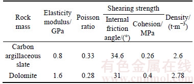
This study was conducted in No.4 ore block of Tangdan copper mine located in a typical copper fissures zone of China. No.4 ore block is 120 m long, 16�C20 m wide, 55�C70�� inclined, 100 m high and 530 m deep along the strike. The main rock composition of the ore body and hangingwall is carbon argillaceous slate while the footwall is dolomite. The ore body and its surrounding rock mass are extremely fractured and filled with much mud. In fact, there are 16�C20 joints per meter in the roadway and hangingwall rocks (Fig. 1). Main physical strength parameters of the block masses are listed in Table 1, in which, rock quality of the stope is supposed to be poor.
Although caving mining seemed to be appropriate for the ore block, it was banned due to surface constructions. Similarly, backfill mining was abandoned for lack of sufficient funds. Hence, the shrinkage stoping was considered a proper way of extracting the resource and controlling the surface subsidence. For the sake of ensuring a high ore extraction ratio and mining safety, pressured grout was proposed prior to mining for reinforcing the ore block and providing a safe span.
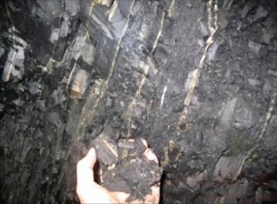
Fig. 1 Rock fractures of No. 4 ore block with much mud
Table 1 Main strength paremeters of No. 4 ore block masses
2.2 Optimization of grout parameters
Firstly, it will be followed by an interpretation of slurry diffusion mechanism as shown in Fig. 2(a). When grouted, slurry is piped and squeezed into zones with much cracks under the help of hole packer, then it combines with the surrounding rock masses. In this way, fractured rock masses are reinforced. Figure 2(b) indicates a hole packer��s working conditions when the fractured deposit is being grouted [9].
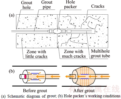
Fig. 2 Grout diffusion mechanism:
2.2.1 Materials ratio
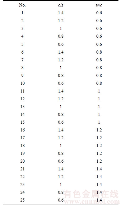
During the selection of grout materials, cement and sodium-silicate(c and s) slurry were analogically chosen to grout the fractured ore body based upon the engineering observation holes, in which many fractures were about 2��10�C3 m wide with cost factor taken into consideration [10]. The water-to-cement ratio (w/c) and cement-sodium silicate are both important parameters which would greatly influence the rheological properties, coherent structure and compactness of slurry, namely, they are key factors for grouting. To optimize cement grout parameters suitable for the mine, rock mass strength test before and after grout based upon L25(56) orthogonal design with c/s and w/c as two factors were carried out. P.O 32.5 ordinary Portland cement was selected and both test levels are listed in Table 2.
According to Table 2, specific test schemes are listed in Table 3.
Table 2 L25(56) table of c/s and w/c
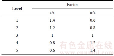
Table 3 Schemes of orthogonal test
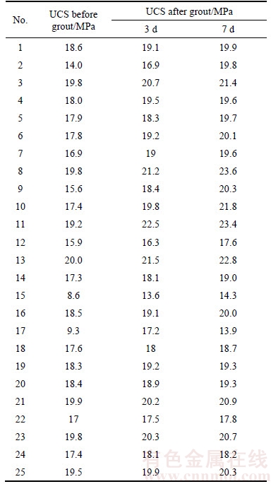
In view of the test schemes above, 25 spots were chosen randomly to chisel rock blocks in the test stope of No.4 ore body to conduct mechanics experiment. All the blocks were made into standard specimen, of which the scale was d80 mm��160 mm. WES-100 hydraulic universal testing machine was employed to confirm the uniaxial compressive strength(UCS). Thereafter, YGZ-90 type of rock drill was used to drill grout holes and HFV�C5D type of grouting machine was employed to grout with the designed 25 levels in Table 2. And then,after grout, the UCS of rock blocks excavated from the 25 spots would be measured when the time was 3 d and 7 d. All the spots should be tested 3 times at least, and the mean value is listed in Table 4.
Table 4 Test results before and after grout
Analyzed by Origin 7.5, relationships between rock strength with c/s and w/c were depicted as Figs. 3 and 4.
Analytically, grout technique could obviously improve strength of the original rock mass. The grouted rock mass would change accompanied with the variation of w/c and c/s. For instance, rock strength was improved obviously after 3 d; further, it would be improved by 4%�C6%. From Fig. 4, it could be known that with w/c being larger and c/s becoming less, on one hand, on the left of level 10, rock strength was exponentially increased significantly , and reached its highest value at level 10; while on the other hand, on the right of level 10, the growth of rock strength became slower.
Therefore, through the experiment, we can know the optimal w/c and c/s should be 0.8 and 0.6, respectively.
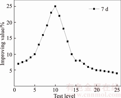
Fig. 3 Relationship between c/s and rock strength after grout (taking 7 d for example)
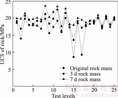
Fig. 4 Relationship between w/c and rock strength before and after grout
2.2.2 Grout pressure
Another research issue to be tackled is grout pressure. The final pressure (P) is a key technical parameter for grout. According to the regulation of GBJ213�C90 specification, P is defined as 2�C4 times the hydrostatic pressure which can be expressed as Eq. (1).
 (1)
(1)
where �� represents influence coefficient of the rock stratum; P0 is the hydrostatic pressure of the grout site.
For an illustrative purpose, P is overwhelmingly influenced by slurry type and the injectable capacity of the rock stratum based on much engineering practice. By experience, for cement-sodium silicate slurry, P is designed 6 times P0 according to the conditions of No. 4 ore block, of which P0 is about 2 MPa. Under this circumstance, P is confirmed as 5�C8 MPa finally.
2.2.3 Grout radius
Last, as described above, rock mass of No.4 ore block is fractured, and its joint fissures are abundant. Analytically, move mode of grout in such stratum should be filling and diffusing. Therefore, LIU Jia-cai equation, i.e., Eq. (2) was selected to calculate grout radius of this mine [11].
 (2)
(2)
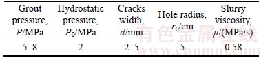
where R represents effective grout radius; P and P0 are the final grout and hydrostatic pressure respectively; r0 is hole radius; �� is slurry viscosity; d is cracks width of the rock mass, and T represents grout time. Related data known before are given in Table 5.
Table 5 Related parameters known before
Via calculation, grout radius could be simplified as Eq. (3).
 (3)
(3)
Result was obvious that grout radius was dominated by pressure, grout time and cracks width. In order to properly investigate relationships between them, relative grout trials were conducted. The measured results of grout radius and time were recorded when pressure was set for 5 MPa and 8 MPa while cracks were accordingly assumed for 0.2, 0.3, and 0.5 cm wide respectively, then analyzed by origin, relationships between grout radius and time were depicted in Fig. 5. It showed that slurry diffusion range would increase rapidly with the increase of grout pressure, then it became slow when grout time came to 1800�C2100 s. Further, accompany with cracks width being bigger, slurry diffusion range would expand fast. When pressure came to 5 MPa, slurry diffusion range could maximum reach 6 m away; otherwise, it would be 8 m while pressure was 8 MPa, at the moment, grout time was 2100 s. Hereafter, as time went on, slurry diffusion range changed slightly. Analytically, the reason might be that slurry began to be concretionary and could not expand outside easily when it arrived at a certain degree. Therefore, grout radius could be considered 6�C8 m which could greatly reduce engineering quantities like drilling holes.
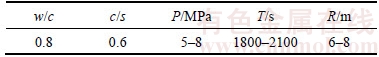
Hence, in order to make the pressure sufficient and time reasonable, key proper parameters of grout were finally recommended as Table 6.
2.3 Effect test of grout
In order to investigate the effect of the pressured grout in the fractured No. 4 ore block, experiment was conducted on the spot. The rooms and pillars were distributed by regular strips alternately along the strike to hold the roof and hangingwall stable. Additionally, 2 rows of grout holes were arranged along the roadway, of which, the spacing was 12 m, namely, grout radius was 6 m. In June 2015, the grout test was completed.
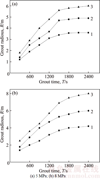
Fig. 5 Diffusion curves under different grout pressures (cracks width: 1�C0.2 cm; 2�C0.3 cm; 3�C0.5 cm):
Table 6 Recommended key parameters of cement-sodium silicate grout
Observation method with drilling peep instrument and technical method with rock mechanical experiment were employed to investigate grout effect [12]. Firstly, holes circumstances (Fig. 6) were observed with drilling peep instrument before and after grout, in which, the un-grouted rock mass was fractured while the grouted fissures were dense and rock fragments rarely occurred. Secondly, the physical strength parameters (Table 7) of rock cores taken out after grout were experimented in the laboratory. Compared with Table 1, parameters of the grouted ore rock were all improved obviously in different degrees. Further, stability and integrity of ore body after grout would be greatly improved, theoretically, ore recovery rate could be improved to increase the economic benefit of Tangdan copper mine by expanding room span [13].
2.4 Three-dimensional numerical simulation
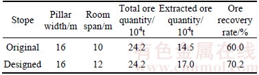
Theoretically, the room spans would be increased greatly for the positive role played by pressured grout. In order to extract ore as much as possible while maintaining mining safety, new stoping configuration was designed [14]. The related parameters are listed in Table 8. Obviously, recovery rate of the newly designed stope was superior to the original; however, three-dimensional numerical simulation ought to be conducted to verify its security and reasonability [15].

Fig. 6 Observed holes circumstances:
Table 7 Main physical strength paremeters of No. 4 ore block masses after grout
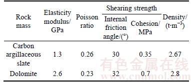
Table 8 Key factors of stopes designed and original
ANSYS (version 11.0) was employed to build geometric model of the ore-bearing rock, whereafter, it was exported to FLAC 3D for further processing. Firstly, geometric models of stope designed and the original were built, thereinto, different stoping structures were arranged with different colors (Fig. 7). And then, the corresponding numerical models were established. Both models scales were limited to 600 m��624 m��658 m whose model units number was 150000 according to the stoping structure.
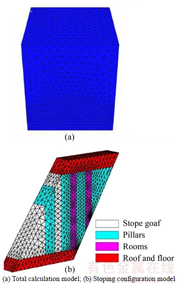
Fig. 7 Numerical simulation models of No. 4 ore block:
Before calculating, all materials were assumed to comply with the Mohr-Coulomb yield criterion in the model, and geotechnical mechanical parameters were stemmed from Table 5. In the course of numerical simulation, the original state of rock should be calculated firstly. Surface was seen as a free boundary, and the horizontal constraint would be applied to the left and right boundaries, while both level and vertical constraints were added to the bottom boundary, of which the boundary stress was supposed to be applied as Eq. (4), accordingly, the distribution nephogram of the rock stress was depicted in Fig. 8. Finally, based upon conditions mentioned above, the room was designed to be excavated from the bottom and left to right according to the actual mining process.
 (4)
(4)
where ��xx, ��yy and ��zz depict the stress in the x, y and z directions, respectively; �� is the bulk density of the rock mass; H is the mining depth, and �� represents the Poisson ratio of the ore rock.
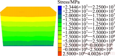
Fig. 8 Distribution nephogram of rock stress (z-direction)
3 Analytical results and discussion
3.1 Surface movements
Restraint applied for surface movements aimed to slow down the surface settlement to an acceptable level [16]. For an illustrative purpose, indexes of surface movements mainly contained subsidence, incline, curvature and horizontal deformation. Figure 9 shows that the surface subsidence was distributed concentrically, and the closer to the goaf, the larger the subsidence was; vice versa.

Fig. 9 Subsidence nephogram of surface
Surface movements curves of the model were drawn in Fig. 10, of which the maximum surface subsidence depth (Fig. 10(a)), incline extent (Fig. 10(b)), curvature radius (Fig. 10(c)) and horizontal deformation (Fig. 10(d)) were limited to 67.47 mm, 3.061 mm/m, 2.187 km and 1.490 mm/m, respectively. Analytically, according to Chinese mining regulations, surface constructions of Tangdan copper mine would be protected as Class I [17], namely disturbance applied to surface constructions was slight while employing some proper support methods after allowable deformation.
3.2 Roof subsidence
The roof subsidence nephogram (Fig. 11) showed a certain scale of settlement happened in the roof after mining. Subsidence around the left side of the roof and hangingwall was worse than other zones which was in accordance with goaf distributions and surrounding rock intensity differences between the hangingwall and footwall. Analytically, the maximum roof subsidence was 201.32 mm before grout while it was 176.46 mm after grout, which was roof subsidence in the newly designed stope was about 25 mm less than the original. Therefore, it was well illustrated that while excavated, new room span of the stope would be better than the original.
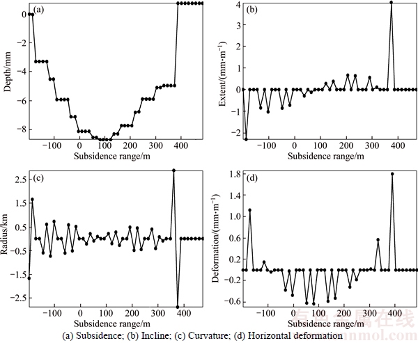
Fig. 10 Movements curves of surface:
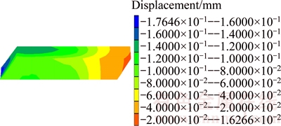
Fig. 11 Roof subsidence nephogram of designed stope
3.3 Maximum principal stress of pillars
The maximum principal stress nephogram of the pillars is depicted as Fig. 12.
From Fig. 12, it could be inferred that stress concentration would occur in the top and bottom of the pillars after mining. The stress concentration factor and the maximum principal stress of the stope designed were 1.16 and 17.650 MPa, respectively, while they were 1.69 and 15.023 MPa correspondingly in the previous stope. Though the maximum principal stress of the stope designed was bigger, the stress concentration factor was much less compared with the original stope [18]. Therefore, the newly designed room span could ensure mining safety, and in view of increasing ore recovery rate, it was better than the previous stoping configuration.
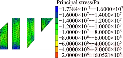
Fig. 12 Maximum principal stress nephogram of pillars in newly designed stope
Three-dimensional numerical simulation used in this study was to optimize the stoping configuration including room span and pillar width. The simulation model had two functions, i.e., objective function and constraint function [19�C21]. The former was ore recovery rate; however, the later mainly consisted of secure indicators, like surface movements, roof subsidence, and maximum principal stress of the pillars.
As was analyzed above, ore recovery rate would be increased by 10.2% employing the newly designed stoping configuration after grout compared with the previous. Meanwhile, simulation results of all the three secure indicators showed the newly designed room span could ensure mining safety. Therefore, pressured grout could obviously reinforce the fractured rock masses before mining to achieve a high ore recovery rate while maintaining the safe mining by optimizing stoping configuration.
4 Conclusions
1) The ore body of No.4 ore block of Tangdan copper mine is extremely fractured and filled with bulk of mud, indicating that rock quality of the stope is fairly poor.
2) To ensure a high ore extraction ratio and mining safety, pre-reinforcement grout technology is proposed prior to mining for supporting the ore block. Hence, related grout parameters such as c/s, pressure, time and radius are calculated and defined as 1:0.5, 5�C8 MPa, 1800�C2100 s, and 6�C8 m, respectively.
3) Through observation, the un-grouted rock mass is fractured while the grouted fissures are dense and rock fragments rarely occur. Based on experiments in the laboratory, parameters of the grouted ore rock are improved obviously in different degrees. After grout, stability and integrity of ore body are greatly improved; theoretically, ore recovery rate of Tangdan copper mine is able to be improved by expanding room span.
4) Softwares of ANSYS and FLAC 3D are proposed to optimize stoping configuration. Simulation results show that ore recovery rate will be increased by 10.2% employing the newly designed stoping structure after grout compared with the previous. And analyzed from surface movements, roof subsidence and the maximum principal stress of the pillars, new stoping configuration may ensure the safe mining.
References
[1] WACLAWIK P, PTACEK J, KONICEK P, KUKUSTSCH R, NEMCIK J. Stress-state monitoring of coal pillars during room and pillar extraction [J]. Journal of Sustainable Mining, 2015, 15(2): 49�C56.
[2] JIANG B, WANG L, LU Y, SUN X, JIN G. Ground pressure and overlying strata structure for a repeated mining face of residual coal after room and pillar mining [J]. International Journal of Mining Science and Technology, 2016, 26(4): 645�C652.
[3] BOGERT H, JUNG S J, LIM H W. Room and pillar stope design in highly fractured area [J]. International Journal of Rock Mechanics and Mining Sciences, 1997, 34(3, 4): 145�C158.
[4] LIU Qin, LIU Zhi-xiang, LIU Ai-hua, LI Wei. Chaotic optimization of structural parameters in gold mining field [J]. Journal of Mining & Safety Engineering, 2010, 27(4): 549�C552. (in Chinese)
[5] DONG Jin-kui, FENG Xia-ting, ZHANG Xi-wei, ZHANG Zhong-hui. Stability evaluation and parameter optimization on the fractured rock mass around underground stope [J]. Journal of Northeastern University: Natural Science, 2013, 34(9): 1322�C1326. (in Chinese)
[6] LI Shu-cai, WANG Hong-tao, WANG Qi, JIANG Bei, WANG Fu-qi, GUO Nian-bo, LIU Wen-jiang, REN Yao-xi. Failure mechanism of bolting support and high-strength bolt-grouting technology for deep and soft surrounding rock with high stress [J]. Journal of Central South University, 2016, 23(2): 440�C448.
[7] DAI Y S, TAN Y H, WU J H, WANG W, LU C H. Properties of bolt-grouting mortar modified with mineral bauxite by chemical activation [J]. Journal of Materials in Civil Engineering, 2016, 28(8): 04016057.
[8] GAO F, STEAD D, KANG H. Numerical simulation of squeezing failure in a coal mine roadway due to mining-induced stresses [J]. Rock Mechanics and Rock Engineering, 2015, 48(4): 1635�C1645.
[9] WANG Q, WANG S, SLOAN S W, SHENG D, PAKZAD R. Experimental investigation of pressure grouting in sand [J]. Soils and Foundations, 2016, 56(2): 161�C173.
[10] NIKBAKHTAN B, OSANLOO M. Effect of grout pressure and grout flow on soil physical and mechanical properties in jet grouting operations [J]. International Journal of Rock Mechanics & Mining Sciences, 2009, 23(46): 498�C505.
[11] BRAS A,  V, CHASTRE C. Development of an injectable grout for concrete repair and strengthening [J]. Cement and Concrete Composites, 2013, 37(3): 185�C195.
[12] STEVE D H. ZOU, CHENG Jiu-long, YUE Ren-jie, SUN Xiao-yun. Grout quality and its impact on guided ultrasonic waves in grouted rock bolts [J]. Journal of Applied Geophysics, 2010, 72 (2): 102�C106.
[13] ZHENG G, ZHANG X S, DIAO Y, LEI H Y. Experimental study on grouting in underconsolidated soil to control excessive settlement [J]. Natural Hazards, 2016, 83(3): 1�C19.
[14] DAI Hua-yang, LI Wen-chang, LIU Yi-xin, JIANG Yao-dong. Numerical simulation of surface movement laws under different unconsolidated layers thickness [J]. Transactions of Nonferrous Metals society of China, 2011, 21(s3): 599�C603.
[15] SUKANTA K. DASH, SWASTI SUNDER MONDAL, SATISH K. AJMANI. Mathematical simulation of surface wave created in a mold due to submerged entry nozzle [J]. International Journal of Numerical Methods for Heat & Fluid Flow, 2004, 14(5): 606�C632.
[16] CHEN Shong-loong, LI Guo-wei, GUI Meen-wah. Effects of overburden, rock strength and pillar width on the safety of a three-parallel-hole tunnel [J]. Journal of Zhejiang University: Science A, 2009, 10(11): 1581�C1588.
[17] SHNORHOKIAN S, MITRI H S, LINDSAY M V. Stability assessment of stope sequence scenarios in a diminishing ore pillar original research article [J]. International Journal of Rock Mechanics and Mining Sciences, 2015, 74: 103�C118.
[18] CAI Mei-feng, LAI Xing-ping. Evaluation on stability of stope structure based on nonlinear dynamics of coupling artificial neural network [J]. Journal of University of Science and Technology Beijing, 2002, 9(1): 1�C4.
[19] DOHERTY J P. A numerical study into factors affecting stress and pore pressure in free draining mine stopes [J]. Computers and Geotechnics, 2015, 63: 331�C341.
[20] PEI Ming-song, XU Meng-guo, WANG Ping, JIAO Ao, WANG Chuang, ZHANG Kai-xin. Optimization of stoping sequence during combined mining at Chengchao Iron Mine by numerical simulation [J]. Journal of Wuhan University of Science and Technology, 2016, 39(2): 107�C111. (in Chinese)
[21] SHI Xiu-zhi, GOU Yong-gang, CHEN Xin, LUO Jia. Determination and application of the backfill thickness in the residual ore recovery of crown and sill pillar [J]. Journal of Mining & Safety Engineering, 2016, 33(6): 1080�C1088. (in Chinese)
(Edited by HE Yun-bin)
Cite this article as: YU Shao-feng, WU Ai-xiang, WANG Yi-ming, LI Tao. Pre-reinforcement grout in fractured rock masses and numerical simulation for optimizing shrinkage stoping configuration [J]. Journal of Central South University, 2017, 24(12): 2924�C2931. DOI:https://doi.org/10.1007/s11771-017-3706-3.
Foundation item: Projects(51374034, 51674012) supported by the National Natural Science Foundation of China; Project(2013BAB02B05) supported by the China National Science and Technology Support Program during the 12th Five-Year Plan Period
Received date: 2016-03-04; Accepted date: 2017-03-17
Corresponding author: WANG Yi-ming, Associate Professor; Tel: +86�C18612693758; E-mail: wangymustb66@sina.com

