J. Cent. South Univ. (2016) 23: 2024-2035
DOI: 10.1007/s11771-016-3259-x

Optimization of geometric parameters of reinforced sheets based on a cell-based smoothed discrete shear gap (CS-FEM-DSG3) method
Mehrdad Sarafrazi, Armen Adamian
Mechanical Engineering Department, School of Engineering, Central Tehran Branch,Islamic Azad University, Tehran, Iran
 Central South University Press and Springer-Verlag Berlin Heidelberg 2016
Abstract: Optimization of design features of reinforced sheet is investigated. Initially, equations governing composite structures are extracted based on Kirchhoff sheet model under bending using Hamilton��s principal. Then, design parameters for the composite structure are extracted with simple supportive boundary conditions from proposed solution. Next, optimization is achieved by determining dimensions of a reinforced sheet specimen. Weight optimization of reinforced sheet structure has been obtained based on variations in thickness and number of longitudinal and transverse reinforcements. Buckling static characteristic is utilized in optimization process. To solve the extracted equations, semi-analytical method of CS-DSG3 has been applied. Results are presented in graphs that show variation of design parameters by changing the geometric parameters. ABAQUS software has been used for design verification. The results show that an increase in thickness of 3 mm skip value tends to be zero. Also, there is a change in the amount of deflection for sheets with a minimum thickness of 3 mm by increasing the number of longitudinal and transverse reinforcement. There is a good agreement between the numerical method of finite elements and the method X-FEM-DSG3.
Key words: optimization; reinforced sheet; design; CS-FEM-DSG3 method
1 Introduction
The use of composite structures has become popular in many engineering fields such as the aeronautical and aerospace industry, marine, aviation, civil, sport, as well as in other fields of modern technology and other applications. Moreover, recently, large commercial transport airplanes are certified to use composite structures in almost the entire structure, and therefore, it even enlarges more branches of possible uses of composites structures, such as in larger civil and naval ships [1-2]. This is because composite structures have high performance and reliability due to high specific strength and high specific stiffness, excellent fatigue strength, resistance to corrosion, and most importantly the design flexibility for desired applications.
There are numerous studies in literature regarding analysis of composite structures by various methods. PALANI et al [3] used both elements (eight and nine-node elements iso-parametric) and element of three nodes beam for analysis of reinforced sheets. KANG and LEISSA [4] formulated an exact solution using a Frobenius series for analysis of rectangular sheets buckling with two simple agents against another when these edges are under tensional effect by linear changes. LUONG and TRI [5] investigated the stability of thin rectangular elastic sheets where its thickness varies according to a sinusoidal process and also they determined critical load for various boundary conditions using approximation method of weighted residuals. CIANCIO and REYES [6] in 2002 started to determine the critical load of buckling of thin circular sheets and hollow circular through Rayleigh method. TAYSI [7] optimized critical load on reinforced sheets with same edges. The position of reinforcements in this study was chosen based on various designs and critical load of buckling. They also used the finite element method to calculate the critical load of sheets�� buckling. In 2011, OU et al [8] investigated the free vibration of rectangular reinforced sheets by finite element method. The results showed that the natural frequency is affected by reinforcements and their position.
For analysis of composite plates, some laminate theories integrated with various numerical methods have been proposed. LIU and NGUYEN-THOI [9] have integrated the strain smoothing technique into the FEM to create a series of smoothed FEM (S-FEM) such as a cell/element-based smoothed FEM (CS-FEM) [10�C12], a node-based smoothed FEM (NS-FEM) [13], an edge-based smoothed FEM (ES-FEM) [14-16] and a face-based smoothed FEM (FS-FEM) [17]. Each of these smoothed FEM has different properties and has been used to produce desired solutions for a wide class of benchmark and practical mechanics problems, especially for various plate problems [18-26]. Among these S-FEM models, the CS-FEM [9-10] shows some interesting properties in the solid mechanics problems. Extending the idea of the CS-FEM to plate structures, NGUYEN- THOI et al [27] have recently formulated a cell-based smoothed discrete shear gap (CS-FEM-DSG3) method using triangular elements for static and free vibration analyses of Mindlin plates by incorporating the CS-FEM with the original DSG3 element [28]. In the CS-FEM-DSG3, each triangular element will be divided into three sub-triangles, and in each sub-triangle, the stabilized DSG3 is used to compute the strains. Then, the strain smoothing technique on whole triangular element is used to smooth the strains on these three sub-triangles. The numerical results showed that the CS-FEM-DSG3 is free of shear locking and achieves the high accuracy compared to the exact solutions and others existing elements in the literature. The CS-FEM-DSG3 then has been extended to analyze various plate and shell problems such as flat shells [28], stiffened plates [29], FGM plates [30], piezoelectricity plates [31] and composite plates resting on foundation [32].
Recently, PHUNG-VAN et al [33-34] proposed a CS-FEM-DSG3 based on the first-order shear deformation theory (FSDT) for static and dynamics analyses of Mindlin plates. The accuracy and reliability of the proposed method was verified by comparing its numerical solutions with those of others available numerical results. NGUYEN-MINH et al [35] conducted Vibrogrounds static and amplified analysis of reinforced sheet by using CS-FEM-DSG3 model. In this study, the accuracy was compared by the numerical solution methods.
WANG and ABDALLA [36] carried out local and overall buckling analysis of composite reinforced sheets. ZHAO and KAPANIA [37] conducted a curved buckling analysis of composite sheets. In this study, the finite element method (finite element) and first order shear deformation theory (first- order shear-deformation theory) were used. GE et al [38] investigated numerically and experimentally composite sheets reinforced by bending the plate and shear (shear and in-plane bending). The results showed there is a good agreement between the finite element method (finite element) and experimental methods.
In this work, the parameters of reinforced sheet weights will be optimized based on geometric parameters of designs through semi-analytical method. Initially, equations governing composite structures (sheet and reinforcement) will be extracted based on Kirchhoff sheet model under bending using Hamilton��s principal and then by making a reinforced sheet structure with certain geometric dimensions of weight parameters optimization. In the present work, verification by ABAQUS software is used to authenticate results.
2 Governing relations
2.1 Energy relations for reinforced flat sheets
Consider a reinforced crib sheets as Fig. 1 indicates. Median plate of the sheets is considered as Oxy reference page. The plate area is defined as  Distance of sectional area of reinforcements from median plane of the sheet is indicated by e. u and v respectively are the orders of displacement in direction, and x, y and w show the skips of plate toward z. ��x and ��y respectively are also normal rotations on median plane around the x and y axes where their positive direction is shown in Fig. 1 [29].
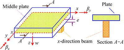
Fig. 1 Introduction of reference coordinates for reinforced crib sheets [29]
2.1.1 Energy relations for sheets
Displacement relations in every part of the sheet are expressed as follows [29]:
 (1)
(1)
So, generally, it��s possible to define all points�� displacement square as a vector:
 (2)
(2)
According to displacement square, membranous, flexural and shear strains are defined as follows [29]:
 (3)
(3)
 (4)
(4)
 (5)
(5)
2.1.1.1 Elastic strain energy of sheet
Elastic strain energy for a flat sheet is determined by the following equation [29]:
 (6)
(6)
where Dm, Db and Ds, respectively, are membranous, flexural and shear hardness and will be defined as follows:


 (7)
(7)

 (8)
(8)
2.1.1.2 Kinetic energy of sheet
Kinetic energy for crib sheets is determined from the following equation [29]:
 (9)
(9)
Equation (9) can be expressed in matrix form as follows:
 (10)
(10)
where  and partial derivative Tcompared to time and also matrix is a diagonal, which is defined as follows:
 (11)
(11)
2.1.1.3 Geometric strain energy of sheet
Relations of Eqs. (3), (4) and (5) represent the elastic strain for the crib sheets and sum of the elastic strain is defined as the combination of three membranous, the flexural and shear elastic strains [29]:
 (12)
(12)
Therefore, the total strain for the sheet in addition to elastic strain includes strain geometry:
 (13)
(13)
where  is strain geometry and is calculated as follows [29]:
 (14)
(14)
In this way, geometric strain energy can be calculated by the following equation:
 (15)
(15)
where  is in-plane pre-buckling stresses.

Substituting Eq. (14) in Eq. (15) and integrating over thickness of the plate, geometric strain energy equation of crib sheet is as follows [29]:
 (16)
(16)
where matrixes of  and ��0 are defined as follows:

 (17)
(17)
 (18)
(18)
And matrix of  is defined as
 (19)
(19)
Substituting Eq. (17) in Eq. (16), geometric strain energy of crib sheets is calculated as follows:
 (20)
(20)
2.1.2 Relationships of energy for reinforcement
According to Fig. 2, the displacement of reinforcement beams can be presented based on displacement of median plane of the plate in local coordinate system.
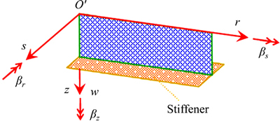
Fig. 2 Local coordinate system on stiffener beam [29]
According to the direction of the stiffener, based on Fig. 2, the local coordinate system of O��rsz will be defined in such a way that O��rs on Oxy (median plane sheet) which is shown in Fig. 1 is coincidental.
Here, it is assumed that sheet displacement and stiffener are equal with each other in contacts location and stiffener rotation around z axis and its lateral displacement are ignored. Therefore, the displacement of stiffener beam can be presented based on the displacement of sheet median plane in local coordinate system:
 (21)
(21)
2.1.2.1 Elastic strain energy for stiffener
Stiffener elastic strain can be calculated from the following relation [29]:
 (22)
(22)
And Stiffener elastic strain can be calculated as follows:
 (23)
(23)
where A and l are stiffener cross-sectional area and length, and matrix DSt also depends on stiffener material and is defined as follows:
 (24)
(24)
With placement of Eq. (22) in Eq. (23) and integration over stiffener cross-sectional area, the relation of stiffener elastic strain energy will be as follows:

 (25)
(25)
where e is the geometric center distance of stiffener cross-sectional area from sheet median plane. It is possible to omit the last section from Eq. (25) regardless of sheet flexural and shear energy.

 (26)
(26)
According to Timoshenko beam theory, coefficient of k=5/6 is considered for shear strain energy and regardless of negligence of stiffener lateral deflection it��s possible to replace G(Is+Iz) with torsional encountering of VANANT of J��0.025A4/Ir. In this equation, Ir is the second stiffener cross sectional around the parallel axis with r axis from geometric center. Thus, stiffener elastic strain energy is simplified in matrix form as follows [29]:
 (27)
(27)
where
 (28)
(28)
And
 (29)
(29)
or in another form:
 (30)
(30)
It is possible to transfer the displacement square from the local coordinate system to global coordinate system.
 (31)
(31)
where A is transition matrix; nx and ny are directional cosines. So, elastic strain in the global coordinate system is given by
 (32)
(32)
in which
 (33)
(33)
In the above equation, we have 

With the substitution of Eq. (32) in Eq. (27), the stiffener elastic strain energy is calculated as follows:
 (34)
(34)
2.1.2.2 Stiffener kinetic energy
Stiffener kinetic energy is determined by the following equation [29]:
 (35)
(35)
 (36)
(36)
And matrix mSt is defined as follows:
 (37)
(37)
2.1.2.3 Stiffener geometric strain energy
As the relationships have been proposed for the sheet, stiffener beam strains include two parts of elastic strain and geometric strain:
 (38)
(38)
where elastic strain  is determined by the following equation:
 (39)
(39)
And stiffener geometric strain energy is defined as follows:
 (40)
(40)
where  is sheet pre-buckling stress for stiffener and is defined as
  and with the substitution of Eq. (39) in Eq. (40) and integration over stiffeners cross section, there is
 (41)
(41)
in which  and
and  are determined as follows [31]:
 (42)
(42)
 (43)
(43)
Also it��s possible to present the geometric strain in global coordinate system as follows:
 (44)
(44)
With substitution of Eq. (44) in Eq. (41), geometric strain energy equation is written as follows:
 (45)
(45)
2.1.3 Potential energy and total kinetic energy
After determining the geometric elastic strain energy and kinetic energy for stiffener and sheet, potential energy and total kinetic energy can be expressed as follows:
 (46)
(46)
 (47)
(47)
2.1.4 Hamilton principal
According to this principal, in sustainable systems, the total amount of potential and kinetic energy is constant in system and is equal to the external forces exerted on the system:
 (48)
(48)
where W is work of external force; t1 and t2 are the identifier of desired timeframe. Some of the energy terms will be deleted to solve the problem in two static and buckling parts.
1) In static analysis, the kinetic energy and geometric strain energy are equal to zero.
2) In buckling analysis, the kinetic energy and work of external force are equal to zero.
2.1.4.1 Static analysis
With the placement of Eqs. (8) and (34) in Eqs. (46), (47) and (48), Hamilton Principal can be written as follows:

 (49)
(49)
where b is the external force.
2.1.4.2 Buckling analysis
For buckling analysis, Hamilton equation is expressed as follows:


 (50)
(50)
2.2 Cell-based smoothed discrete shear gap method
Problem optimization takes place by considering CS-DSG3 method in Ref. [29] for both static and buckling mode.
3 Results and discussion
The purpose of this section is to determine critical load of sheet buckling by changing the parameters of sheet thickness and stiffener and ultimately determining the optimal value for the weight of the structure. The problem for one sheet with dimension of 1 m��1 m and simple fulcrum boundary conditions at the edges is solved. Stiffener section is considered as T-shaped (Fig. 3). In order to ensure the correctness of program performance, initially, an example will be calculated through MATLAB software code based on mentioned equations and then the results will be accurately checked with results obtained from ABAQUS software. Numbering of nodes is shown in Fig. 4.
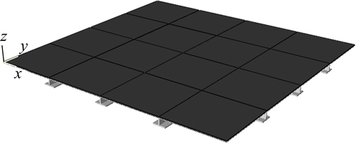
Fig. 3 Reinforced sheet with orthogonal beams and T-shaped cross section
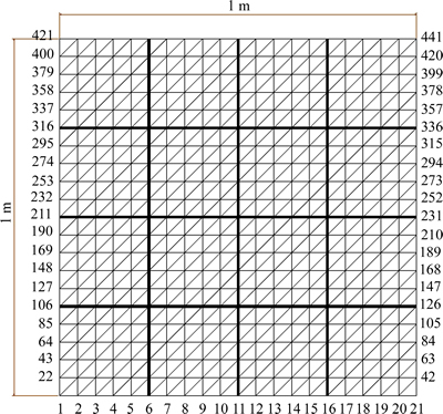
Fig. 4 Meshing of reinforced sheet
3.1 Verification
In this section, verification has been done by using Ref. [35] and numerical solution.
3.1.1 Verification based on Ref. [11]
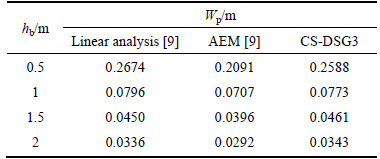
To validate the results, numerical example brought from Ref. [35] and presented results has been compared with mentioned reference. Consider a Lx��Ly=18��9 m2 rectangular reinforced sheet in which thickness is hp= 0.2 m, elasticity modulus is E=3��107 kN/m2 and Poisson ratio is ��=0.2 that is reinforced by 1 m cross-section width reinforcement beam. Boundary conditions are considered at plate��s transverse edges and they are free at longitudinal edges. The reinforced beam is bounded at both ends as well. The plate is under g=160 kN/m2 lateral pressure (Fig. 5). Maximum rise in the center of the plate mentioned in lieu of different values (Beam��s height) in the Table 1.
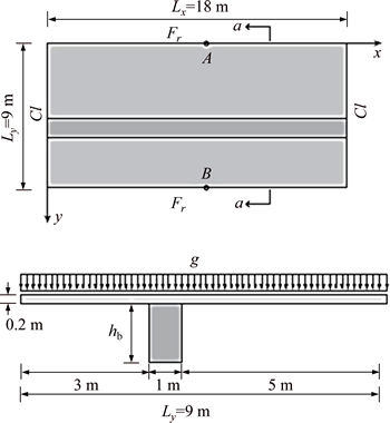
Fig. 5 Reinforced plate dimensions under lateral load
Table 1 Rising values at center of plate
3.1.2 Verification based on numerical method
Sheet dimension is 1 m��1 m and its thickness is 5 mm. Sheet and stiffeners are made from steel with a modulus of elasticity of E=206 GPa. Also, cross sections of stiffeners are T-shaped and its dimensions are shown in Fig. 6. Geometric properties of cross section are as follows: Stiffener��s cross section, A=400 mm2; Distance of stiffener geometric center to sheet median plane, e=25.9375 mm; Second moment of inertia of level around of axis passing through the center toward s, Is=40481.772 mm4; Second moment of inertia of level around of axis passing through the center toward z, Iz=52395.833 mm4; Torsional moment of inertia of section, J=92877.604 mm4.
Contour of deformation reinforced sheet is drown under the side pressure of P=100 kPa with ABAQUS software (Fig. 7). As it can be seen, the maximum leap is 3.371 mm and is in middle plane. Deformation of the sheet diagram is drawn by MATLAB software (Fig. 8).
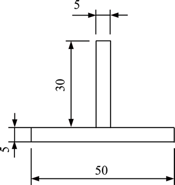
Fig. 6 Cross section of reinforced beams T50��30��5 (Unit: mm)
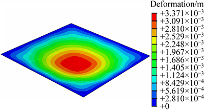
Fig. 7 Deformation of sheet in ABAQUS Software
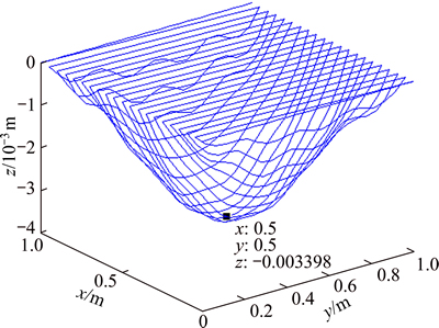
Fig. 8 Deformation of sheet in MATLAB software
Its maximum leap is 3.398 mm and its situation is exactly in the center of sheet. As it is indicated, derived results from analysis of MATLAB and ABAQUS software are matched with each other and they verify the accuracy and validity of MATLAB.
3.2 Optimization
Now, it is possible to start the optimization process and design parameters as follows: Sheet thickness, tplate=1, 2, 3, ��, 10 mm; Number of stiffeners in longitudinal direction, Ny,St=0, 1, 3, 4; Numbers of stiffeners in transverse direction, Nx,St=0, 1, 3, 4.
Note that the thickness of stiffener cross sections in all steps of analysis is equal to sheet thickness and also all inputs are summarized as follows: Modulus of elasticity of sheets and stiffeners, E=206 GPa; Sheet and stiffeners Poisson coefficient, ��=0.3; Boundary conditions at the edges of the sheet: simple fulcrum; Forced power: pressure P=100 kPa; Sheet dimension:1 m��1 m.
3.2.1 Changes of leap under static load
Variation of leap with sheet thickness and number of longitudinal and transverse stiffeners is shown in Table 2. Since the purpose of optimization is reducing the mass of structures, it is necessary to normalize obtained leap values to the mass. The normalized leap is defined as: W=��Aw/M, in which �� is density, A is sheet area, M is the total mass of the structure, w is leap and W is dimensionless leap. The densities of sheet and stiffeners are considered equal to be 7800 kg/m3. The values of structure mass for different states of sheet thickness and number of stiffeners are given in Table 3. So, the values of dimensionless leap for various sheet thicknesses and the number of stiffeners are brought in Table 4. As its clear from Tables 2 and 4, with the increase of longitudinal and transverse stiffeners and also sheet thickness, the reinforced sheet leap will decrease. Results show that with the increase of longitudinal and transverse, steep of leap reduction will reduce.
In continuation, we have changes of normalized leap based on changes in number of longitudinal and transverse stiffeners (Figs. 9-13). As it can be seen, increase of thickness from the determined amount (approximately 2.5 mm) causes no changes in number of normalized leap.
3.2.2 Critical load changes of buckling
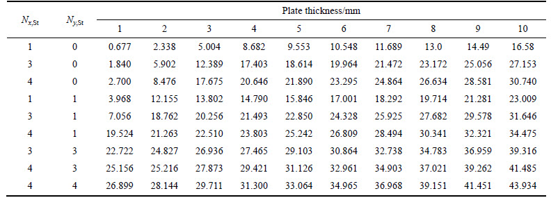
Critical buckling load variation with increase of thickness and longitudinal and transverse stiffener changes are presented. The values of critical load variation of reinforced sheet to structures mass for sheet thickness variations and changes in numbers of stiffeners are brought in Figs. 14-17 and Table 5. As it can be obtained, with the increase of thickness and the number of longitudinal and transverse stiffeners, the ratio of critical buckling load changes to structure mass will increase. Results in low thickness and low stiffeners of critical buckling load changes to structure mass has high slope. With increasing the thickness and the number of stiffeners, the slope of the graph of proportion of critical buckling load changes to structure mass has milder conditions.
Teble 2 Sheet leap changes (mm) with sheet thickness and number of stiffener
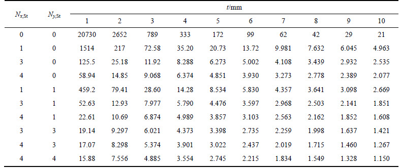
Table 3 Values of structural mass (kg)
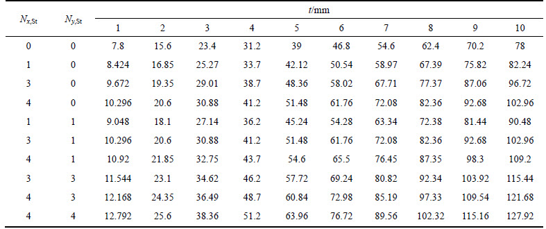
Table 4 Values of dimensionless leap
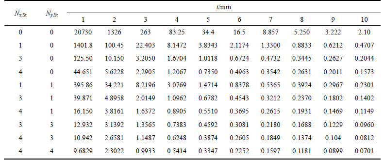
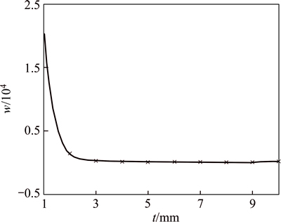
Fig. 9 Variation in sheet leap with increasing sheet thickness for Ny,St=0 and Nx,St=0
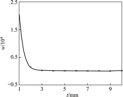
Fig. 10 Variation in sheet leap with thickness increases for Ny,St=0
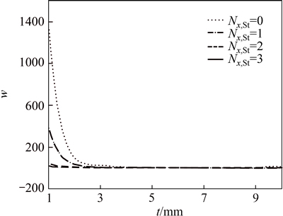
Fig. 11 Variation in sheet leap with thickness increases for Ny,St=1
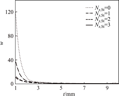
Fig. 12 Variation in sheet leap with thickness increases for Ny,St=3
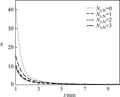
Fig. 13 Variation in sheet leap with increasing sheet thickness for Ny,St=4
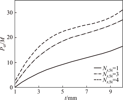
Fig. 14 Variations in ratio of critical buckling load to structures mass with increasing sheet thickness for Ny,St=0
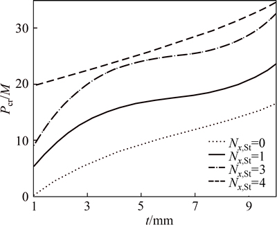
Fig. 15 Variations in ratio of critical buckling load to structures mass with increasing sheet thickness of Ny,St=1
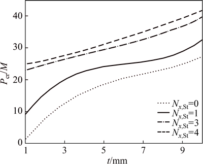
Fig. 16 Variations in ratio of critical buckling load to structures mass with increasing sheet thickness for Ny,St=3
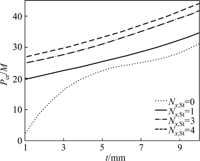
Fig. 17 Variation in ratio of critical buckling load to structures mass with increasing sheet thickness for Ny,St=4
4 Conclusions
Most important parameters in designing reinforced structures are the number and angels of stiffeners, their spaces from each other, sheet thickness and number of stiffeners. Verification has been obtained based on numerical solution of finite element and semi-analytical solution of CS-DSG3. Analysis and optimization of reinforced isotope sheet has been obtained.
Table 5 Values of critical load-buckling to-mass
1)��Extraction of sheet leap and critical loading buckling has been obtained based on CS-DSG3 method and the verification is achieved through the results of finite element analysis.
2) Comparison of numerical analyses of isotope sheet with T-shape stiffeners with finite element results indicates almost 1% difference, which validates the authenticity of the above method.
3) The result show that, with the increase of thickness and the number of stiffeners, leap variation slope will decrease and it will be in a linear mode.
4) With the increase in thickness and number of stiffeners, the slope of buckling critical loading to mass decreases.
5) When the minimum thickness of reinforced sheet is 3 mm, by increasing the number of longitudinal and transverse reinforcement, the change of the structure mass is not observed.
References
[1] MOURITZ A P, GELLERT E, BURCHILL P, CHALLIS K. Review of advanced composite structures for naval ships and submarines [J]. Composite Structures, 2001, 53(1): 21-42.
[2] ACEVES C M, SKORDOS A A, SUTCLIFFE M P. Design selection methodology for composite structures [J]. Materials & Design, 2008, 29(2): 418-426.
[3] PALANI G S, IYER N R, RAO T A. An efficient finite element model for static and vibration analysis of eccentrically stiffened plates/shells [J]. Computers & Structures, 1992, 43(4): 651-661.
[4] KANG J H, LEISSA A W. Exact solutions for the buckling of rectangular plates having linearly varying in-plane loading on two opposite simply supported edges [J]. International Journal of Solids and Structures, 2005, 42(14): 4220-4238.
[5] LUONG N T, TRI T H. Influence of variable thickness on stability of rectangular plate under compression [J]. Mechanics Research Communications, 2005, 32(2): 139-146.
[6] CIANCIO P M, REYES J A. Buckling of circular, annular plates of continuously variable thickness used as internal bulkheads in submersibles [J]. Ocean Engineering, 2003, 30(11): 1323-1333.
[7]  N. Determination of thickness and stiffener locations for optimization of critical buckling load of stiffened plates [J]. Scientific Research and Essays, 2010, 5(9): 897-910.
[8] OU D Y, MAK C M, KONG P R. Free flexural vibration analysis of stiffened plates with general elastic boundary supports [J]. World Journal of Modelling and Simulation, 2012, 8(2): 96-102.
[9] LIU G R, NGUYEN-THOI T. Smoothed finite element methods [M]. New York: Taylor and Francis, 2010: 822-827.
[10] LIU G R, DAI KY, NGUYEN T T. A smoothed finite element method for mechanics problems [J]. Computational Mechanics, 2007, 39(6): 859-877.
[11] LIU G R, NGUYEN T T, DAI KY, LAM K Y. Theoretical aspects of the smoothed finite element method (SFEM) [J]. International Journal for Numerical Methods in Engineering, 2007, 71(8): 902-930.
[12] LIU G R, NGUYEN-THOI T, NGUYEN-XUAN H, DAI KY, LAM K Y. On the essence and the evaluation of the shape functions for the smoothed finite element method (SFEM) [J]. International Journal for Numerical Methods in Engineering. 2009, 77(13): 1863-1869.
[13] NGUYEN-THOI T, LIU G R, NGUYEN-XUAN H. Additional properties of the node-based smoothed finite element method (NS-FEM) for solid mechanics problems [J]. International Journal of Computational Methods. 2009, 6(4): 633-666.
[14] NGUYEN-XUAN H, LIU G R, NGUYEN-THOI T, NGUYEN- TRAN C. An edge-based smoothed finite element method for analysis of two-dimensional piezoelectric structures [J]. Smart Materials and Structures, 2009, 18(6): 065015.
[15] LIU G R, NGUYEN-XUAN H, NGUYEN-THOI T. A theoretical study on NS/ES-FEM: Properties, accuracy and convergence rates [J]. Int J Numer Methods Eng, 2010, 84: 1222-1256.
[16] NGUYEN-THOI T, LIU G R, NGUYEN-XUAN H. An n-sided polygonal edge based smoothed finite element method (nES FEM) for solid mechanics [J]. International Journal for Numerical Methods in Biomedical Engineering, 2011, 27(9): 1446-1472.
[17] NGUYEN-THOI T, LIU G R, LAM KY, ZHANG G Y. A face-based smoothed finite element method (FS-FEM) for 3D linear and geometrically non-linear solid mechanics problems using 4-node tetrahedral elements [J]. International Journal for Numerical Methods in Engineering, 2009, 78(3): 324-353.
[18] NGUYEN-XUAN H, LIU G R, THAI-HOANG C, NGUYEN-THOI T. An edge-based smoothed finite element method (ES-FEM) with stabilized discrete shear gap technique for analysis of Reissner�CMindlin plates [J]. Computer Methods in Applied Mechanics and Engineering, 2010, 199(9): 471-489.
[19] NGUYEN-XUAN H, RABCZUK T, NGUYEN-THANH N, NGUYEN-THOI T, BORDAS S. A node-based smoothed finite element method with stabilized discrete shear gap technique for analysis of Reissner�CMindlin plates [J]. Computational Mechanics, 2010, 46(5): 679-701.
[20] NGUYEN-XUAN H, TRAN L V, NGUYEN-THOI T, VU-DO H C. Analysis of functionally graded plates using an edge-based smoothed finite element method [J]. Composite Structures, 2011, 93(11): 3019-3039.
[21] THAI C H, TRAN L V, TRAN D T, NGUYEN-THOI T, NGUYEN- XUAN H. Analysis of laminated composite plates using higher-order shear deformation plate theory and node-based smoothed discrete shear gap method [J]. Applied Mathematical Modelling, 2012, 36(11): 5657-5677.
[22] NGUYEN-XUAN H, TRAN L V, THAI C H, NGUYEN-THOI T. Analysis of functionally graded plates by an efficient finite element method with node-based strain smoothing [J]. Thin-Walled Structures, 2012, 54: 1-8.
[23] NGUYEN-THOI T, PHUNG-VAN P, LUONG-VAN H, NGUYEN- VAN H, NGUYEN-XUAN H. A cell-based smoothed three-node Mindlin plate element (CS-MIN3) for static and free vibration analyses of plates [J]. Computational Mechanics, 2013, 51(1): 65-81.
[24] PHUNG-VAN P, NGUYEN-THOI T, LUONG-VAN H, LIEU- XUAN Q. Geometrically nonlinear analysis of functionally graded plates using a cell-based smoothed three-node plate element (CS-MIN3) based on the C 0-HSDT [J]. Computer Methods in Applied Mechanics and Engineering, 2014, 270: 15-36.
[25] LUONG-VAN H, NGUYEN-THOI T, LIU GR, PHUNG-VAN P. A cell-based smoothed finite element method using three-node shear-locking free Mindlin plate element (CS-FEM-MIN3) for dynamic response of laminated composite plates on viscoelastic foundation [J]. Engineering Analysis with Boundary Elements, 2014, 42: 8-19.
[26] NATARAJAN S, KALEESWARAN K, MANICKAM G. Functionally graded material panel flutter by cell-based smoothed finite elements [J]. Journal of Coupled Systems and Multiscale Dynamics, 2013, 1(2): 205-215.
[27] NGUYEN-THOI T, PHUNG-VAN P, NGUYEN-XUAN H, THAI- HOANG C. A cell based smoothed discrete shear gap method using triangular elements for static and free vibration analyses of Reissner�CMindlin plates [J]. International Journal for Numerical Methods in Engineering, 2012, 91(7): 705-741.
[28] BLETZINGER K U, BISCHOFF M, RAMM E. A unified approach for shear-locking-free triangular and rectangular shell finite elements [J]. Computers & Structures, 2000, 75(3): 321-334.
[29] NGUYEN-THOI T, BUI-XUAN T, PHUNG-VAN P, NGUYEN- XUAN H, NGO-THANH P. Static, free vibration and buckling analyses of stiffened plates by CS-FEM-DSG3 using triangular elements [J]. Computers & Structures, 2013, 125: 100-113.
[30] PHUNG-VAN P, NGUYEN-THOI T, TRAN LV, NGUYEN-XUAN H. A cell-based smoothed discrete shear gap method (CS-DSG3) based on the C0-type higher-order shear deformation theory for static and free vibration analyses of functionally graded plates [J]. Computational Materials Science, 2013, 79: 857-872.
[31] PHUNG-VAN P, NGUYEN-THOI T, LE-DINH T, NGUYEN- XUAN H. Static and free vibration analyses and dynamic control of composite plates integrated with piezoelectric sensors and actuators by the cell-based smoothed discrete shear gap method (CS-FEM- DSG3) [J]. Smart Materials and Structures, 2013, 22(9): 095026.
[32] NGUYEN-THOI T, LUONG-VAN H, PHUNG-VAN P, RABCZUK T, TRAN-TRUNG D. Dynamic responses of composite plates on the Pasternak foundation subjected to a moving mass by a cell-based smoothed discrete shear gap (CS-FEM-DSG3) method [J]. International Journal of Composite Materials, 2013, 3A: 19-27.
[33] PHUNG-VAN P, NGUYEN-THOI T, DANG-TRUNG H, NGUYEN-MINH N. A cell-based smoothed discrete shear gap method (CS-FEM-DSG3) using layerwise theory based on the C0-HSDT for analyses of composite plates [J]. Composite Structures, 2014, 111: 553-565.
[34] PHUNG-VAN P, NGUYEN-THOI T, LUONG-VANH THAI-HOANG C, NGUYEN-XUAN H. A cell-based smoothed discrete shear gap method (CS-FEM-DSG3) using layerwise deformation theory for dynamic response of composite plates resting on viscoelastic foundation [J]. Computer Methods in Applied Mechanics and Engineering, 2014, 272: 138-159.
[35] NGUYEN-MINH N, NGUYEN-THOI T, BUI-XUAN T, VO-DUY T. Static and free vibration analyses of stiffened folded plates using a cell-based smoothed discrete shear gap method (CS-FEM-DSG3) [J]. Applied Mathematics and Computation, 2015, 266: 212-234.
[36] WANG D, ABDALLA M M. Global and local buckling analysis of grid-stiffened composite panels [J]. Composite Structures, 2015, 119: 767-776.
[37] ZHAO W, KAPANIA R K. Buckling analysis of unitized curvilinearly stiffened composite panels [J]. Composite Structures, 2016, 135: 365-382.
[38] GE D, MO Y, HE B, WU Y, DU X. Experimental and numerical investigation of stiffened composite curved panel under shear and in-plane bending [J]. Composite Structures, 2016, 137: 185-195.
(Edited by YANG Bing)
Received date: 2015-03-18; Accepted date: 2015-12-25
Corresponding author: Mehrdad Sarafrazi; Tel: +98-21-77894887; E-mail: mehrdad.sarafrazi@gmail.com

