
Phase-field simulation of lamellar growth for a binary eutectic alloy
LI Xin-zhong(李新中)1, 2, LIU Dong-mei(刘冬梅)1, SUN Tao(孙 涛)2,
SU Yan-qing(苏彦庆)1, GUO Jing-jie(郭景杰)1, FU Heng-zhi(傅恒志)1
1. School of Materials Science and Engineering, Harbin Institute of Technology, Harbin 150001, China;
2. School of Mechatronics Engineering, Harbin Institute of Technology, Harbin 150001, China
Received 10 October 2008; accepted 4 January2009
Abstract: Using general multi-phase-field model, detailed microstructures corresponding to different initial lamellar sets were simulated in a binary eutectic alloy with an asymmetric phase diagram. The simulation results show that regular or unstable oscillating lamellar structures depend on the initial lamellar widths of two solid phases. A lamellar morphology map associating with the initial widths has been derived, which is capable of showing the condition of forming various lamella structures. For instance, a regular lamella was formed with fast solidification while large lamella resulted from disorder growth with low interfacial velocity. The investigated interface velocities indicate that with fast solidification to form regular lamella, a disorder growth manner or a large lamellar spacing causes a low interface velocity. These results are in good agreement with those proposed by Jackson-Hunt model.
Key words: phase-field simulation; microstructure, eutectic; lamella
1 Introduction
In the last decade, the phase-field method has been widely used to simulate microstructure evolution during phase transitions of pure materials and alloys. The first model for alloy solidification of liquid-solid transition was proposed by WHEELER et al[1-2], which is late named as WBM model. The WBM model has been the most extensively used one in dealing with ideal solutions of binary alloys[1, 3-7]. Subsequently, KIM et al[8] proposed a similar phase-field model for binary alloys, named KKS model, which is equivalent to the WBM model, but has a more appropriate definition of the free energy density for the interfacial region. Presently, the KKS model has been widely used in order to simulate microstructure evolution in solidification of dilute solutions[9-10]. In addition, multi-phase-field model [11-21], which is a natural extension of basic phase-field concept of liquid-solid transition, offers the perspective for simulating microstructure evolution of eutectic, peritectic and even monotectic transitions. Recently, NESTLER and WHEELER[16-17] made a further extension of their previous work[12] and constructed a new multi-phase-field model for binary alloys involving one liquid phase and two solid phases. It is general to represent eutectic or peritectic reaction by adjusting its parameters accordingly.
For eutectic systems, the fundamental theoretical understanding of steady eutectic growth can be found in Jackson-Hunt model[22]. In this work, we aim to simulate binary eutectic solidification by multi-phase- field model to investigate the detailed microstructure changes in response to different initial lamellar sets.
2 Multi-phase-field model
The detailed derivation of multi-phase-field model can be found in Ref.[16], which is generally valid for most transitions among multiple phases. These equations of this model that ensure the total energy to decrease monotonically in time and the total amount of solution system to be conserved can be written as

 (1)
(1)

 (2)
(2)
where
 (3)
(3)
 (4)
(4)
 (5)
(5)
 (6)
(6)
 (7)
(7)
 (8)
(8)

 (9)
(9)
M1 can be formulated to relate directly to the kinetic mobility of different interfaces[15]; εi, j is the gradient energy coefficient related to interface thickness and surface energy of the interface between phases labeled i and j; ri, j is defined to be the antisymmetric term;  is the barrier height between phases i and j for the case of pure A and B, respectively;
  is the bulk free energy of pure A and B states, respectively; λ is the Lagrange multiplier and imposes the constraint given in Eq.(3); LA and
  are the latent heat of fusion per unit volume and the melting temperature of the solid phase i of the pure component A, respectively; LB and
  have the similar interpretation; Vm is the molar volume; and Di is the solute diffusion coefficient of the phase i.
The above equations can be non-dimensional by introducing new dimensionless variables[16]:


 (10)
(10)
where l* is a characteristic length scale associated with the macroscopic interfacial morphology; t is the time and has been scaled with the corresponding solute diffusion time; and T* is the eutectic temperature of a binary alloy.
3 Simulation results
The binary eutectic solidification with two solid phases α and β has been simulated based on the multi- phase-field model presented above. A model alloy with an asymmetric phase diagram is chosen according to Ref.[16]. The dimensionless computational parameters are taken as 
 LA=1.5, LB=1.1, M1=1.18×10⁸,
  εi, j=
 The calculation is performed on a 200×1 200 grid on a rectangle domain with a space step of
  2.2×10⁻⁴, and a time step of
  1.0×10⁻⁸. The solidification of α and β solid phases is investigated from a slightly undercooled melt of
  0.997. The initial composition of c=0.422 8 (molar fraction or mass fraction, %) is set in α-phase, c=0.577 2 in β-phase and c=0.5 in liquid.
Different initial lamellar sets adjusted through the initial lamellar widths of α and β phases are defined as λα and λβ, respectively. Their values can be changed by setting different numbers of initial seeds of each phase at the bottom of the calculation domain, which also causes the variation of initial lamellar spacing, here λ=λα+λβ.
We take into account of the situation of λα/λβ=1 with different lamellar spacings. The simulation results are shown in Fig.1. Fig.1(a) shows the lamellar morphology and compositional distribution in front of interface at different solidification time when λα=λβ= The white region represents α, and the black one represents β. During the initial stage of solidification, both solid phases grow fast into undercooled melt. Those lamellae maintain their initial widths but become time-dependent gradually. The solid/liquid interfaces of both phases are convex. There exists a region of solute-rich liquid ahead of α-phase due to the rejection of solute at the interface and a corresponding lean region of liquid ahead of β-phase. Subsequently, the interfacial morphology of each lamella is no longer strictly convex and has developed into central region concave just like a traveling wave propagating across the front of the interface[20], which causes the lamella to be slanted to the growth direction. At the end, one can observe that the system is unable to develop a steady state and evolves to an unstable oscillating structure (we called irregular lamellae here), while lamellar spacing and interface morphology change continuously. The oscillation period along growth direction is about

Fig.1 Simulation of eutectic lamellar structures at same ratio of initial lamellar width between α and β phases with different lamellar spacings (White region represents α and black for β): (a) λα=λβ= (b) λα=λβ=
 (c) λα=λβ=
Fig.1(b) shows the simulation result when λα=λβ=  One can observe that a regular lamellar structure is formed. The lamellae maintain their initial widths and flat interface morphologies from initial transient to steady state growth.
Fig.1(c) shows the result when taking λα=λβ= Because the initial lamellar spacing is too small, it is subjected to spatial instability and magnifies from center to two lateral sides of the computation domain. This causes the increasing growth of lamella nearby and slant to the growth direction. Consequently, a lamella of one phase displaces its neighboring lamella of another phase with some lamellae being eliminated from initial array gradually. Subsequently, the instability near the central starts to operate and causes the oscillation of lamellae. One can observe that one phase overgrows and displaces its neighboring lamella with prolonging solidification time. The system is also unable to develop a steady state evolving in an unstable oscillating structure like that in Fig.1(a).
Next, we investigate the situation of λα?λβ≠1 with different lamellar spacings. The corresponding simulation results are shown in Fig.2. Fig.2(a) shows the microstructure evolution at different solidification time when λα=10 and λβ=50. The large difference of initial lamellar widths between two solid phases also means a large difference of lamellar spacing between them, which causes oscillation amplitude to increase significantly. This oscillation makes the system unstable. One can see that one phase overgrows and tries to displace its neighboring phase. The solid/liquid interfaces of both phases show a larger curvature than that in Fig.1. Finally, one lamella of α-phase eliminates, showing an island morphology, and then the system evolves in a disorder manner.

Fig.2 Simulation of eutectic lamellar structures at different ratios of initial lamellar width between α and β phases, and different lamellar spacing (White region represents α and black represents β): (a) λα=10 and λβ=50; (b) λα=10 and λβ=40; (c) λα=10 and λβ=30; (d) λα=10 and λβ=15
Fig.2(b) shows the similar result when λα=10 and λβ=40, in which α-phase shows large difference of growth pattern, and some are eliminated, showing an island morphology; and others overgrow significantly with a flower morphology. Fig.2(c) shows the result of an irregular lamellar structure when λα=10 and λβ=30. Compared with the results in Figs.2(a) and (b), it shows higher ordering with regular structure and smaller interface curvature. The oscillation period along growth direction is about 10.28. When λα=10 and λβ=15, simulation result in Fig.2(d) shows a regular lamellar structure. Initially, slight oscillation exists in the system, causing lamellae near the lateral sides to slant to the growth direction slightly, but the amplitude decreases steadily.
If each initial set between phases α and β in Fig.1 and Fig.2 is interchanged, such as the initial lamella with λα=10and λβ=50 in Fig.2(a), the simulation results show identical growth pattern with lamellar morphology corresponding to interchange phases α and β. These results can be attributed to the cooperative growth manner between two solid phases.
4 Discussion
In the present simulations, the melt undercooling is constant, and the spacing of regular lamellar structure, λr, is correlated with undercooling according to Jackson- Hunt model[22]. The simulation results in Fig.1 and Fig.2 show the value of λr to be (10-30). Because the initial lamellar spacing is set artificially by specifying the lamellar widths of both solid phases with larger or lower than λr, the oscillation appears to make initial lamellae grow appropriately to adjust their spacings to approach λr. The larger the difference between initial lamellar spacing and λr, the larger the amplitude of oscillation. This amplitude determines the irregular degree of lamella, such as the slightly irregular manner in Fig.1(a) and extremely disorder manner in Fig.2(a) and Fig.2(b).
Fig.3 gives the final lamellar morphology map associated to the initial lamellar widths of both phases based on our simulation results. The shaded region of triangle B-C-D is determined, where regular lamellar structure can be formed. The region of triangle A-B-D corresponds to a possible regular lamellar structure after a relatively long solidification time in initial transient. In Fig.3, the line through points A and C is defined as Line 1 where the points satisfy λα=λβ. The simulation results reveal that any two points symmetric on Line 1 have the identical growth pattern, such as points B and D, points E and E′. In Fig.3, the arrows indicate the tendency away from Line 1 and the triangle B-C-D is corresponded to the irregular degree of lamellar structure. So, the solidification with large difference between λα and λβ corresponds to the unstable oscillating lamellar structure.

Fig.3 Final lamellar morphology map determined by initial lamellar widths of phases α and β
By recording the positions of solid/liquid interface at some solidification time, the interface velocities can be calculated. Fig.4 gives the interface velocities at time corresponding to the eutectic solidifications in Fig.1 and
Fig.2. One can see that the interface velocities of each eutectic solidification decrease with solidification time and tends to approximate one value gradually. Further considering the lamellar morphologies, one can find that the eutectic solidification forming regularly lamellar structure has larger value of interface velocity than that forming unstable oscillating lamellar structure. Furthermore, the more regular the lamellar structure or the smaller the lamellar spacing is, the larger the interface velocity is. It is well known that the advance of eutectic solidification depends on the interdiffusion between phases α and β. Phase α provides solvent atoms to phase β, and phase β provides solute atoms to phase α. Such a diffusion couple ensures the cooperative growth of both phases. Obviously, a disorder growth manner or a large lamellar spacing will reduce the speed of interdiffusion, leading to lower interface velocity.
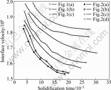
Fig.4 Interface velocities corresponding to solidification time at different eutectic solidifications
5 Conclusions
1) The multi-phase-field simulation shows regular or unstable oscillating lamellar structure dependent on the initial lamellar widths. A lamellar morphology map determined by initial widths of both phases has been derived. According to the map, regularly lamellar structure can be formed when initial lamellar spacing is in the order of ( -
- . The solidification with large difference of initial lamellar widths is corresponding to the unstable oscillating lamellar structure.
2) The investigation of interface velocity indicates that eutectic solidification forming regularly lamellar structure has larger value of interface velocity than that forming unstable oscillating lamella. Furthermore, the more regular the lamellar structure or the smaller the lamellar spacing is, the larger the interface velocity is.
3) The simulation results are in good agreement with those obtained by Jackson-Hunt model.
References
[1] WHEELER A A, BOETTINGER W J, McFADDEN G B. Phase-field model for isothermal transition in binary alloys [J]. Phys Rev A, 1992, 45: 7424-7439.
[2] WARREN J A, BOETTINGER W J. Prediction of dendritic growth and microsegregation patterns in a binary alloy using the phase-field method [J]. Acta Metall Mater, 1995, 43: 689-703.
[3] AHMAD N A, WHEELER A A, BOETTINGER W J, McFADDEN G B. Solute trapping and solute drag in a phase-field model of rapid solidification [J]. Phys Rev E, 1998, 58: 3436-3450.
[4] FILHO R N, KOSTERLITZ J M, GRANATO E. Pattern selection in a phase field model for directional solidification [J]. Physica A, 2005, 354: 333-343.
[5] TAKAKI T, FUKUOKA T, TOMITA Y. Phase-field simulation during directional solidification of a binary alloy using adaptive finite element method [J]. Journal of Crystal Growth, 2005, 283: 263-278.
[6] MILLER W, RASIN I. Growth kinetics by means of phase-field methods in applied crystal growths [J]. Journal of Crystal Growth, 2007, 303: 95-99.
[7] GUO Jing-jie, LI Xin-zhong, SU Yan-qing, WU Shi-ping, LI Bang-sheng, FU Heng-zhi. Phase-field simulation of structure evolution at high growth velocities during directional solidification of Ti55Al45 alloy [J]. Intermetallics, 2005, 13: 275-279.
[8] KIM S G, KIM W T, SUZUKI T. Phase-field model for binary alloys [J]. Phys Rev E, 1999, 60: 7186-7197.
[9] SUZUKI T, ODE M, KIM S G, KIM W T. Phase-field model of dendritic growth [J]. J Crystal Growth, 2002, 237: 125-131.
[10] LAN C W, SHIH C J, LEE M H. Quantitative phase field simulation of deep cells in directional solidification of an alloy [J]. Acta Materialia, 2005, 53: 2285-2294.
[11] TIADEN J, NESTLER B, DIEPERS H J, STEINBACH I. The multiphase-field model with an integrated concept for modeling solute diffusion [J]. Physica D, 1998, 115: 73-86.
[12] NESTLER B. A multiphase-field model: Sharp interface asymptotics and numerical simulations of moving phase boundaries and multijunctions [J]. Journal of Crystal Growth, 1999, 204: 224-228.
[13] LEE J S, KIM S G, KIM W T, SUZUKI T. Numerical simulation of peritectic reaction using a multi-phase-field model [J]. ISIJ International, 1999, 39: 730-736.
[14] DROLET F, ELDER K R, GRANT M, KOSTERLITZ J M. Phase-field modeling of eutectic growth [J]. Phys Rev E, 2000, 61: 6705-6720.
[15] HECHT U, GRANASY L, PUSZTAI T, BOTTGER B, APEL M, WITUSIEWICZ V, RATKE L, WILDE J D, FROYEN L, CAMEL D, DREVET B, FAIVARE G, LEGENDRE B, REX S. Multiphase solidification in multicomponent alloys [J]. Materials Science and Engineering R, 2004, 46: 1-49.
[16] NESTLER B, WHEELER A A. A multi-phase-field model of eutectic and peritectic alloys: Numerical simulation of growth structures [J]. Physica D, 2000, 138: 114-143.
[17] NESTLER, DANILOV D. Phase-field simulations of solidification in binary and ternary systems using a finite element method [J]. Journal of Crystal Growth, 2005, 275: 177-182.
[18] NESTLER B. A 3D parallel simulation for crystal growth and solidification in complex alloy systems [J]. Journal of Crystal Growth, 2005, 275: 273-278.
[19] PLAPP M. Three-dimensional phase-field simulations of directional solidification [J]. Journal of Crystal Growth, 2007, 303: 49-57.
[20] YANG Yu-jian, WANG Jin-cheng, YANG Gen-chang, ZHU Yao-chan. Multi-phase field simulation of eutectic morphology selection and interface destabilization [J]. Acta Metallurgica Sinica, 2006, 42(9): 914-918. (in Chinese)
[21] YANG Yu-jian, WANG Jin-cheng, ZHU Yao-chan, ZHANG Yu-xiang, YANG Gen-chang. Multi-phase field simulation of isothermal free binary eutectic growth [J]. Rare Metal Materials and Engineering, 2007, 36(4): 573-577. (in Chinese)
[22] JACKSON A, HUNT D J. Lamellar and rod eutectic growth [J]. TMS AIME, 1966, 236: 1129-1141.
Foundation item: Projects(50771041, 50801019) supported by the National Natural Science Foundation of China; Project(20080430909) supported by China Postdoctoral Science Foundation; Project(HITQNJS. 2008. 018) supported by Development Program for Outstanding Young Teachers in Harbin Institute of Technology, China
Corresponding author: LI Xin-zhong; Tel: +86-451-86418815; E-mail: hitlxz@163.com
DOI: 10.1016/S1003-6326(09)60138-2
(Edited by YANG Hua)

