J. Cent. South Univ. Technol. (2008) 15: 540-544
DOI: 10.1007/s11771-008-0102-z
Pump-lockage ore transportation system for deep sea flexible mining system
XU Hai-liang(徐海良), YIN Ping-wei(尹平伟),
XU Shao-jun(徐绍军), YANG Fang-qiong(杨放琼)
(School of Mechanical and Electrical Engineering, Central South University,
Changsha 410083, China)
Abstract: Based on characteristics of deep sea flexible mining system, a new pump-lockage ore transportation system was designed. According to Bernoulli equation and two-phase hydrodynamics theory, parameters of the new system were obtained and four ore transportation systems were analyzed. The results indicate that the pump head of 1 000 m mining system is 100-150 m and that of 5 000 m mining system is 660-750 m. In addition, based on similarity theory, a model of the new transportation system was made, which can simulate more than 5 000 m actual ore transportation system. So both theory and experiment prove that the new pump-lockage ore transportation system is an ideal design for deep sea flexible mining system.
Key words: flexible mining system; ore transportation system; pump-lockage
1 Introduction
Based on ore transportation differences, deep sea mining systems can be classified into rigid pipe and flexible mining system. CHUNG and CHENG[1-3] made research on rigid pipe mining system in which centrifugal slurry pumps were used to transport ores. Disadvantages of this system are that centrifugal slurry pumps are easily worn down, which may lead to paralysis of the whole mining system[4-6].
In flexible mining system, transportation system consists of flexible hose and ore lifting equipment. Ore lifting equipment is installed on the mining crawler. Advantages of this system are: the long flexible hose allows the mining crawler to collect ores in a wide range of working space; a single mining ship can control several mining crawlers, thus the output of the mining system is increased greatly; when the mining ship meets the great storms, unties the flexible hose, and prevents perils of the sea’s occurrence. For the ore lifting equipment, Siegen University once designed a kind of lifting equipment[7]. But because of seal problem, the equipment cannot meet requirements. Up to now, there is not the equipment that meets requirements of deep sea mining system[8-11]. As a result of the long-term research, the newly designed pump-lockage ore transportation system can satisfy the requirements.
2 Principle of pump-lockage ore transporta- tion system
In the pump-lockage ore transportation system, the new ore lifting equipment is shown in Fig.1. It consists of a multistage clear water pump, two vessels and six lockages. The working principle is as follows.
Step 1 Before the mining system begins to work, lockages 3 and 6 are turned on, others are turned off and the pressure in the vessels and that of sea water are equal. When the clear water pump is turned on, sea water gets into the pump from the inlet and is transported to sea level through flexible hose.
Step 2 After the mining crawler starts working, ores under the action of gravity flow into vessel 1 through lockage 3, and sea water in vessel 1 is drained away through lockage 3. When vessel 1 is filled with ores, turn off lockage 3 and turn on lockages 1 and 2. When pressure in vessel 1 and that of flexible hose are equal, ores in vessel 1 flow into flexible hose under the action of pump, and are transported to the mining ship.
Step 3 Since lockage 3 is turned off, ores flow into vessel 2 through lockage 6. When ores in vessel 1 are carried over and vessel 2 is filled with ores, turn off lockages 1, 2 and 6, meanwhile turn on lockages 3, 4 and 5, ores in vessel 2 will flow into flexible hose and be transported to the mining ship, while ores flow into vessel 1 through lockage 3.

Fig.1 Principle of pump-lockage ore lifting equipment
Repeat the above working steps, the ore transportation system can transport ores continuously from seabed to the mining ship.
3 Analysis on parameters of pump-lockage ore transportation system
3.1 Analysis on parameters of flexible hose
Once the working depth(h) of the mining system is determined, the flexible hose length(L) can be obtained. When the fluid flow(Qm) is determined, the relationship between the internal diameter(Di) and the fluid velocity (um) in flexible hose is as follows:
 (1)
(1)
where subscripts m and i mean fluid and inner, respectively. To make the system work well, the fluid velocity in the vertical flexible hose must be higher than the sink velocity of ores. The sink velocity of ores (ut) can be calculated through the following formula:
 (2)
(2)
where subscripts s, l, and w mean ores, sea water and water, respectively; ds is the diameter of ores; ρl is the density of sea water; ρs is the density of ores; ψ is the spherical drag coefficient of ores.
Based on Govier theory, it is known that, when the fluid velocity is twice more than the sink velocity of ores, ores can be transported to sea level by the fluid. To make sure the flexible hose not be blocked, the fluid velocity is required to be 3-5 times as high as the sink velocity of ores[12-13].
During the working process, it is possible for the transportation flexible hose in a horizontal state, thus the fluid velocity must be higher than a critical velocity so as to avoid flexible hose blockage by sinking ores. For large ores, the calculation formula is[14]:
 (3)
(3)
where ρm is the fluid density; fi is the ratio of ores, when the ores are homogeneous, fi=1; ψi is a coefficient in relation to the size of ores.
Once the fluid velocity is determined, it must be checked by formula (3) (um must be higher than uk) to ensure the ore transportation system in normal working condition.
3.2 Determination of parameters of pump-lockage ore lifting equipment
Based on Bernoulli equation, the pump head (H) is obtained[15-17]:
 (4)
(4)
where po is the outlet pressure of flexible hose; ρw is the density of water; Δhm is the resistance loss of the flexible hose.
In Eqn.(4), only pressure loss (ρm/ρw)Δhm of the flexible hose is unknown.
As for the ores with size of about 30 mm, the pressure loss of the flexible hose can be predicted by Engleman theory:
 (5)
(5)
where ul is the see water velocity; us is the ores velocity; λl is the friction coefficient of sea water with pipe wall; λs is the friction coefficient of ores with pipe wall, ds is the differential length of flexible hose; φV is the volume fraction of fluid; dpm is the differential value of the pressure loss caused by sea water and ores.
From Eqn.(5), the pressure loss of flexible hose is
 (6)
(6)
Through researching, Engleman obtained the empirical formula as follows:
 (7)
(7)
where  is the average diameter of ores;
  is the mass flow of nodules,
  ;
;  is the mass flow of sea water,
The resistance friction coefficient of sea water with pipe wall can be obtained by Reynolds formula:
 (8)
(8)
where Δ is the roughness of internal wall of flexible hose.
Based on Eqns.(6)-(8), the pressure loss of flexible hose Δpm can be obtained. Once Δpm is defined, the pump head can be obtained by Eqn.(4); based on the pump head and the flow, the shaft power of pump N can be calculated:
 (9)
(9)
where PN is the shaft power of pump N; μ is the efficiency of pump, μ=0.80-0.85; Q is the flow of pump, and the flow of pump and that of the fluid are equal, Q=Qm.
4 Calculating analysis on pump-lockage ore transportation system
The main parameters of mining system are listed below: the wet ore productive capacity is 45 t/h; the working depths are 1 000 m and 5 000 m; ore volume fraction of the fluid is 7%-12%; the density of ores is 2 040 kg/m3; the average diameter of ores entering the transportation flexible hose is 30 mm. Based on different volume fractions, 7%, 12%, 10%, 10%, four ore transportation systems were designed and analyzed, respectively. And the parameters of the transportation system are listed in Table 1.
Based on those parameters, it is known that, when working depth of the mining system is 1 000 m, pump heads are 102.61 m and 153.65 m, and the powers are 110 and 96 kW, respectively. When the working depth is 5 000 m, pump heads are 660.70 m and 755.40 m, and the powers are 500 and 560 kW, respectively. Present technology has no trouble in designing and manufacturing the required pumps. Therefore, it is technologically feasible for the pump-lockage combined ore transportation system to transport ores from sea floor to sea level directly.
5 Experimental analysis on ore transporta- tion system
5.1 Experimental model of ore transportation system
The model of the pump-lockage ore lifting equipment is shown in Fig.2. Main parameters are as follows: pump type is QGDa3.5-100-1.5; power is 1.5 kW; pump head is 100 m; flow is 35 m3/h; inner diameter of flexible hose is 0.2 mm.
Table 1 Parameters of ore transportation systems


Fig.2 Model of pump-lockage ore lifting equipment
5.2 Experimental theory of ore transportation system
The design for the model system should be based on similarity theory to meet the conditions of geometrical and kinetic conform.
5.2.1 Geometrical conform
For the pump-lockage ore transportation system, the researching object is the fluid in flexible hose. So the main geometrical parameters are the cross-sectional area of flexible hose and the size of ores.
The geometrical conform coefficient Cm is the ratio of the cross-sectional area of the model flexible hose to that of the actual flexible hose.
 (10)
(10)
where those parameters with subscript M are those of the model system, and parameters with T represent those of the actual system.
The geometrical conform coefficient of ores in the fluid is:
 (11)
(11)
5.2.2 Kinetic conform
The main parameters of kinetic conform for the ore transportation system are the transportation capacity and the transportation height. The transportation capacity of the system is the volume flow of ores, and the kinetic conform of the transportation height should choose the pump head as the calculating parameter. The flow of the ore transportation system is
 (12)
(12)
Based on the above formula, the flow coefficient CQ of the model system and the actual system is
 (13)
(13)
The potential energy and the pressure loss of flexible hose affect the pump head greatly when the fluid kinetic energy is not taken into account. Supposing that the outlet pressure of the pipe is zero and the density of sea water and that of water are equal, the pump head for the ore transportation system can be obtained by Eqn.(4):
 (14)
(14)
The pump head for the model system is
 (15)
(15)
Based on Eqns.(14)-(15), the pump head coefficient (CH) of the model system and the actual system is obtained:

 (16)
(16)
5.3 Analysis on experimental results of ore transport- tation system
Based on the condition of geometrical conform and kinetic conform of the experimental system and the actual system, there exists Cm=Cs=CH=CQ=0.1. The above model system can be adapted to conduct the actual system analysis, of which the pump head is 1 000 m, the flow is 35 m3/h and the diameter of flexible hose is 0.2 m.
Based on model theory, the sand with diameter of 2.0-3.5 mm was chosen as model ores. Based on Eqn.(1), fluid velocity in the model pipe was calculated as 1.96 m/s and density of the sand was 2 700 kg/m3. Based on Eqns.(2) and (3), the sink velocity of the sand is calculated as 0.38 m/s and the critical velocity was 1.8 m/s. From the above analysis, it was known that the experimental system conforms to fluid transporting requirements.
The working principle of the model system is the same as that of the actual system. In experiment, the pressure could be adjusted by the width of lockage 4 in Fig.2. Ore transportation height of the experimental system could be calculated by Eqn.(15). Based on Eqns.(15) and (16), the pump head and the ore transportation height of the actual system could be analyzed. Based on Eqn.(15) and Eqn.(6), the pressure loss of the actual system could be analyzed by choosing a proper length for modeling of flexible hose (about 600 m). In the experiment, only the ore transportation height of the actual system was analyzed and the pressure loss of the flexible hose was ignored.
From the model system, it is known that ore volume fraction in the fluid can be adjusted through lockage 2. Based on the time and flow for carrying over the total ores in the lockage, ores volume fraction in the fluid could be calculated. In the experimental process, the pressure loss caused by injecting the ores into the high-pressure water could be noted down by adjusting the ore volume density in the fluid and the transportation pressure, thus the pressure loss of ore transportation system could be analyzed.
Through analyzing transportation pressure of the model system and the volume fraction of ore in the fluid, transportation height of the actual mining system is listed in Table 2.
Table 2 Experimental data of ore transportation height
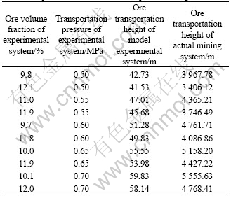
From the experimental results, it is known that, when transportation pressure of the experimental system is 0.7 MPa, ore volume fractions of the fluid are 10.1% and 12.0%. Based on similarity theory, the ore transportation height of the actual system should be 5 555.63 and 4 768.41 m, respectively. Therefore, the pump-lockage combined ore transportation system is an ideal system to transport ores from 5 000 m sea floor to sea level directly.
In the experiment, it is almost impossible to distinguish the data difference measured by the manometers, which is a clear hint to show that the pressure loss caused by injecting ores into the pipe is also very low. Therefore, in the hydraulic analysis of the ore transportation system, it is feasible to ignore the pressure loss caused by injecting ores into pipe.
6 Conclusions
1) The maximum pump head of the new ore transportation system for 5 000 m deep sea flexible mining system is 755.40 m and the pump can be made using modern technology. Therefore, it is technologically feasible for the pump-lockage combined ore transportation system to transport ores from sea floor to sea level directly.
2) The model of the new system, which is made according to similarity theory, can simulate 5 555.63 m actual mining system. The experimental research proves that the new system is ideal for transporting ores from sea floor to sea level directly. In the hydraulic analysis of the system, the slight pressure loss caused by injecting ores into piper can be ignored.
References
[1] CHUNG J S, CHENG B. Application of thrusts to elastic joints on long vertical pipe in 3-D nonlinear motions (Part II): Numerical examples by MSE and FEM results [C]// Proc 8th Int Offshore and Polar Eng Conf. Montactual: ISOPE, 1998: 189-198.
[2] CHUNG J S, CHENG B. 3-D responses of vertical pipe bottom pin-joined to a horizontal pipe to ship motion and thrust on pipe (Part I): MSE and FEM modeling [C]// Proc 9th Int Offshore and Polar Eng Conf. Brest: ISOPE, 1999: 265-271.
[3] CHUNG J S, CHENG B. MSE and FEM modeling of thrusts to elastic joints of long vertical pipe in 3-D nonlinear motions [J]. Int J Offshore and Polar Eng, 1999, 9(2): 117-125.
[4] YU Hong-yun, LIU Shao-jun. Dynamics of vertical pipe in deep-ocean mining system [J]. Journal of Central South University of Technology, 2007, 14(4): 552-556.
[5] HUANG Zhong-hua, LIU Shao-jun, XIE Ya. Obstacle performance of cobalt-enriching crust wheeled mining vehicle [J]. Journal of Central South University of Technology, 2006, 13(2): 180-183.
[6] XIANG Lin-jing. Research on kinematics and dynamics of deep sea mining pipe [D]. Beijing: University of Science and Technology Beijing, 2000: 1-10. (in Chinese)
[7] GREBE H. Amathematical model for the analysis of flexible marine risers [D]. Siegen: Siegen Univeristy, 1997: 1-12. (in Chinese)
[8] ABLOW C M, SCHECHTER S. Numerical simulation of undersea cable dynaimcs [J]. Ocean Engineering, 1983, 10(6): 443-457.
[9] MILINAZZO F, WILKIE M, LATCHMAN S A. An efficient algorithm for simulating the dynamics of towed cable systems [J]. Ocean Engineering, 1987, 14(6): 513-526.
[10] OWEN D G, QIN K. Model tests and analysis of flexible riser systems [J]. Offshore Mechanics and Arctic Engineering, 1986, 3: 354-362.
[11] GHADIMI R. A simple and efficient algorithm for the static and dynamics analysis of flexible marine riser [J]. Computers & Structures, 1988, 29(4): 541-555.
[12] ENGLMANN H E. Vertical hydraulic transportation of large-size―A contribution to marine mining. OCT 3137 [C]// The 10th Annual Offshore Technology Conference. Louisiana: 1978: 216-219.
[13] SMITH P A, STANSBY P K. Postcritical flow around a circular cylinder by the vortex method [J]. Journal of Fluid and Structures, 1989, 3: 275-291.
[14] FEI Xiang-jun. Transporting hydraulics of hydromass and pellet [M]. Beijing: Tsinghua University Press, 1994. (in Chinese)
[15] XU Hai-liang, HE Qing-hua. Deep sea mining ore expulsion system: China, 20004200360 74.2 [P]. 2004. (in Chinese)
[16] XU Hai-liang, HE Qing-hua. Deep sea mining system research [J]. Chinese Mining Industry, 2004, 3(7): 43-46. (in Chinese)
[17] XU Hai-liang, HE Qing-hua. Research on combined single pump and ore tank deep-sea mining transporting system [J]. Journal of Central South University of Technology, 2005, 36(1): 92-96. (in Chinese)
Foundation item: Project(50574100) supported by the National Natural Science Foundation of China
Received date: 2007-12-19; Accepted date: 2008-03-06
Corresponding author: XU Hai-liang, Associate professor, PhD; Tel: +86-731-8877589; E-mail: hailiang_xu@yahoo.com.cn
(Edited by YANG Hua)

