Multi-objective optimization of active steering system with force and displacement coupled control
来源期刊:中南大学学报(英文版)2012年第4期
论文作者:赵万忠 孙培坤 刘顺 林逸
文章页码:974 - 987
Key words:vehicle engineering; active steering; electric power steering; multi-objective genetic algorithm
Abstract: A novel active steering system with force and displacement coupled control (the novel AFS system) was introduced, which has functions of both the active steering and electric power steering. Based on the model of the novel AFS system and the vehicle three-degree of freedom system, the concept and quantitative formulas of the novel AFS system steering performance were proposed. The steering road feel and steering portability were set as the optimizing targets with the steering stability and steering portability as the constraint conditions. According to the features of constrained optimization of multi-variable function, a multi-variable genetic algorithm for the system parameter optimization was designed. The simulation results show that based on parametric optimization of the multi-objective genetic algorithm, the novel AFS system can improve the steering road feel, steering portability and steering stability, thus the optimization method can provide a theoretical basis for the design and optimization of the novel AFS system.
J. Cent. South Univ. (2012) 19: 974-981
DOI: 10.1007/s11771-012-1099-x![]()
ZHAO Wan-zhong(赵万忠)1, 2, SUN Pei-kun(孙培坤)1, LIU Shun(刘顺)1, LIN Yi(林逸)3
1. Department of Vehicle Engineering, Nanjing University of Aeronautics and Astronautics, Nanjing 210016, China;
2. State Key Laboratory of Mechanical Transmission, Chongqing University, Chongqing 400044, China;
3. School of Mechanical and Vehicular Engineering, Beijing Institute of Technology, Beijing 100081, China
? Central South University Press and Springer-Verlag Berlin Heidelberg 2012
Abstract: A novel active steering system with force and displacement coupled control (the novel AFS system) was introduced, which has functions of both the active steering and electric power steering. Based on the model of the novel AFS system and the vehicle three-degree of freedom system, the concept and quantitative formulas of the novel AFS system steering performance were proposed. The steering road feel and steering portability were set as the optimizing targets with the steering stability and steering portability as the constraint conditions. According to the features of constrained optimization of multi-variable function, a multi-variable genetic algorithm for the system parameter optimization was designed. The simulation results show that based on parametric optimization of the multi-objective genetic algorithm, the novel AFS system can improve the steering road feel, steering portability and steering stability, thus the optimization method can provide a theoretical basis for the design and optimization of the novel AFS system.
Key words: vehicle engineering; active steering; electric power steering; multi-objective genetic algorithm
1 Introduction
The electric power steering (EPS) controls the force transfer characteristic of the steering system. It provides good steering portability and steering road feel through the assist control strategy, returnability and damping control strategy [1-3]. Because of the EPS system characteristic, it is especially suitable for the electric vehicles and new energy vehicles. Therefore, the EPS system has a very broad applicable prospect.
The active front steering (AFS) controls the displacement transfer characteristic of the steering system. It provides good handling and stability performance of the vehicle through variable transmission ratio control and active steering intervention control [4-6]. The AFS system incorporates the safety, flexibility and driving pleasure, brings the steering system’s function into full play and greatly improves the steering quality.
At present, the EPS cannot achieve variable ratio control and active steering intervention control to improve handling stability [7-9]. While still using hydraulic system to obtain steering power, the AFS system is complex and inevitably has the disadvantages of hydraulic system, and the oil volumetric flow should be adapted to the output requirements [10-11]. Compared to the EPS system, the AFS system can hardly realize the force and displacement coupled control, returnability and damping control.
Therefore, based on the technique of EPS and AFS, a novel steering system with function of both the AFS and EPS will be the main development direction of automotive steering technique in the future. A novel AFS system with force and displacement coupled control was developed in this work. Based on the dynamic model, the performance index of the portability, road feel and stability of steering was put forward and analyzed. Based on the multi-objective genetic algorithm, a multi-variable genetic algorithm for the novel AFS system was designed, and thus a theoretical basis for the design and optimization of the novel AFS system was provided.
2 Dynamic model
The structure of the novel AFS system is shown in Fig. 1. Two motors are included: one motor is assist motor, providing assistant torque to limit manual forces to a reasonable level [12-14], and the other is steering motor, providing additional steering angle to improve vehicle steering responses and avoid critical handling situations.
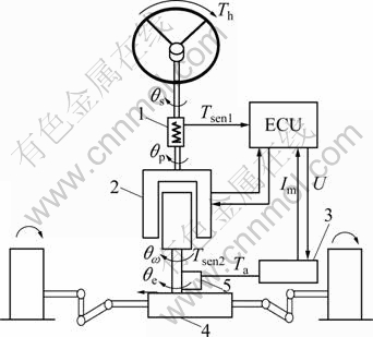
Fig. 1 Structure of novel AFS: 1―Torque sensor; 2―Steering motor; 3―Assist motor; 4―Rack and pinion; 5―Deceleration institution
2.1 Three-freedom model of vehicle
The three-degree of freedom dynamic differential equations for the vehicle can be expressed as
 (1)
(1)
The parameters ![]() and
and ![]() can be described as
can be described as
 (2)
(2)
where g is the acceleration due to gravity; u, ωr, f, β and δ are velocity, yaw rate, roll angle, sideslip angle of the center of mass, and front-wheel steer angle of the vehicle, respectively;![]()
![]() a, b, and h are front-wheel sideslip angle, rear-wheel sideslip angle, distance between the front axle and the center of mass, distance between the rear axle and the vehicle centre of mass, and rolling moment arm of the vehicle, respectively; m, ms, Ix, and Iz are mass, sprung mass, moment of inertia of sprung mass about x axis, and moment of inertia of mass about z axis of the vehicle, respectively; Ixz, k1, k2, E1 and E2 are product of inertia of sprung mass about axes x and z, front-wheel cornering stiffness, rear-wheel cornering stiffness, front roll steer coefficient, and rear roll steer coefficient of the vehicle, respectively; Cf1, Cf2, D1 and D2 are roll angle stiffness of front suspension, roll angle stiffness of rear suspension, roll angle damping of front suspension, and rolling angle damping of rear suspension of the vehicle, respectively.
a, b, and h are front-wheel sideslip angle, rear-wheel sideslip angle, distance between the front axle and the center of mass, distance between the rear axle and the vehicle centre of mass, and rolling moment arm of the vehicle, respectively; m, ms, Ix, and Iz are mass, sprung mass, moment of inertia of sprung mass about x axis, and moment of inertia of mass about z axis of the vehicle, respectively; Ixz, k1, k2, E1 and E2 are product of inertia of sprung mass about axes x and z, front-wheel cornering stiffness, rear-wheel cornering stiffness, front roll steer coefficient, and rear roll steer coefficient of the vehicle, respectively; Cf1, Cf2, D1 and D2 are roll angle stiffness of front suspension, roll angle stiffness of rear suspension, roll angle damping of front suspension, and rolling angle damping of rear suspension of the vehicle, respectively.
2.2 Steering input shaft model
The dynamic equation for the steering input shaft which is connected to the stator of steering motor can be expressed as
![]() (3)
(3)
where Js is moment of inertia of the steering input shaft and steering wheel; θs, Bs and Tsen1 are angle of rotation, damping coefficient, and anti-torque of the input shaft, respectively; Th is the steering torque acting on the steering wheel.
Parameter Tsen1 can be expressed as
![]() (4)
(4)
where Ks is the stiffness coefficient of the input shaft; θp is the angle of rotation of the steering motor’s stator.
2.3 Steering motor model
A permanent magnet brushless servomotor is employed as the steering motor in the novel AFS system. Based on the reference coordinate of the rotor, the voltage equations for the servomotor can be written as
![]() (5)
(5)
where uq is the voltage of the q axis; ud is the voltage of the d axis; id is the current of the d axis; iq is the current of the q axis; Rs is the resistance of the armature winding; k is the voltage gain of the inverter forward path; kf is the current feedback coefficient; Ls is the armature inductance; wm-r is the relative angular velocity of the rotor to the stator; ef is the rotational voltage; p is the pole-pairs. The electromagnetic torque caused by servomotor is obtained by
![]() (6)
(6)
where Ts and ke are the electromagnetic torque and torque coefficient of the servomotor, respectively.
2.4 Steering motor stator model
Taking the transitional linkage which is connected to the stator into consideration, the dynamic equation for the stator of steering motor can be written as
![]() (7)
(7)
where Jp1 and Bp are moment of inertia and damping coefficient of the stator, respectively.
2.5 Steering motor rotor model
The dynamic equation for the of rotor steering motor may be expressed as
![]() (8)
(8)
where Jp2, Tsen2 and θw are the moment of inertia, anti-torque, and angle of rotation of the steering motor rotor, respectively. The Tsen2 can be expressed as
![]() (9)
(9)
where θe is the rotation angle of the output shaft.
2.6 Assist motor model
A permanent magnet motor is employed as the assist motor in the novel AFS system, and the voltage equation of the assist motor is obtained as
![]() (10)
(10)
where U, L, R, Kb, θm and I are voltage, inductance, resistance, back electromotive-force constant, angle of rotation, and current of the assist motor, respectively.
The electromagnetic torque caused by the assist motor can be expressed as
![]() (11)
(11)
where Ka is moment coefficient of the assist motor.
The dynamic equations of the mechanical part of the assist motor can be written as
![]() (12)
(12)
where Jm is moment of inertia of the assist motor and clutch; Bm, Tm and Ta are damping coefficient, electromagnetic torque, and output torque of the assist motor, respectively.
The Ta can be computed by
![]() (13)
(13)
where Km is the output stiffness of the assist motor and deceleration device; G is the transmission ratio from the power motor to the steering screw.
2.7 Output shaft model
The dynamic equation for output shaft is obtained as
![]() (14)
(14)
where Je, Be and Tr are moment of inertia, damping coefficient, and anti-torque of output shaft, respectively.
2.8 Rack and pinion model
The dynamic equation for the rack and pinion can be given by
![]() (15)
(15)
where mr is the effective mass of the rack and pinion; br is the damping coefficient of the rack; xr is the displacement of the rack; rp is the radius of the small pinion; FTR is the axial thrust exerted on the rack.
The FTR can be simplified as
![]() (16)
(16)
where kr is the effective elasticity coefficient; Fδ is the random signal from the road. And θe=xr/rp.
3 Steering performance index
The novel AFS system should have the following performances: 1) Good road feel; 2) Good steering portability; 3) Good steering stability. In order to provide a basis for the optimization design of the novel AFS system, the quantitative formula is proposed.
3.1 Steering road feel
The steering road feel is analyzed by fastening the steering wheel. In this way, the interference information can be transferred to the driver completely. Additionally, it is easier to analyze the system, since one-degree of freedom is reduced. Assume
θs=0 (17)
When the assist motor is assumed as using the current control strategy, and the torque sensor is reduced to the torsion bar spring, the measured value of the torque sensor can be computed by
![]() (18)
(18)
where Tn is the torque received by the torque sensor.
According to the current control strategy, the current can be given by
![]() (19)
(19)
where K is power gain coefficient. Then, Tm can be given by
![]() (20)
(20)
The novel AFS system can be simplified by hypothesizing the front wheel and the steering screw equivalent, and the simplified novel AFS system model contains the following information: 1) G is the transmission ratio from the power motor to steering screw; 2) n1 is the ratio from θp to θw; 3) n2 is the transmission ratio from the steering screw to front wheel; 4) θw is equivalent to θe. It exists the following relations:
 (21)
(21)
where δ is the angle of front wheel. According to Eqs. (3), (4), (7), (8), (12), (14), (17), (20) and (21), the steering road feel E(s), namely the transfer function from Tr to Th, can be computed by
![]() (22)
(22)
where s is the complex variable, and
 .
.
3.2 Steering portability
The steering portability is defined as the ratio from the yaw velocity ωr to the angle of rotation of input shaft θs. According to Eqs. (4), (7), (8), (12), (14), (20) and (21), the transfer function of the steering portability can be expressed as
![]() (23)
(23)
![]()
 (24)
(24)
According to Eqs. (1)-(2),
 (25)
(25)
where


3.3 Steering stability
It is essential to guarantee the steering stability while developing the novel AFS and the vehicle system. Therefore, it is indispensible to analyze how to guarantee the steering stability. So, it is necessary to analyze the requirements of steering stability.
Choose the denominator of the transfer function of steering portability (Eq. (23)) as the requirement of steering stability, then
![]() (26)
(26)
where


The Routh list of this function is expressed as
 (27)
(27)
In accordance with the requirements of the Routh criterion, the numbers in the first column should be all positive.
4 Parameters optimization
4.1 Design variables
Considering that some parameters of the vehicle are unchangeable, the power gain coefficient K varies with the speed, and the friction coefficients cannot be changed randomly. Therefore, n1, G and Ks (N・m/rad) can be chosen as the design variables. Namely
 (28)
(28)
4.2 Objective function
In order to transfer the information from the road to the driver completely, the average frequency power of the steering road feel should be as much as possible in a certain frequency range. The objective function f is the average frequency power of the steering road feel in the (0, ω0) frequency range, and ω0 is designed as 40 Hz, namely,
![]() (29)
(29)
In order to get good steering portability for the vehicle, the average frequency power of the steering portability should be in an appropriate range. The objective function g is the average frequency power of steering portability in (0, ω0) frequency range, and ω0 is designed as 40 Hz, namely,
![]() (30)
(30)
In order to pledge both the steering road feel and steering portability, the average frequency power of the steering portability should be optimized. The objective function gf is the sum of the average frequency power of steering road feel and steering portability with weight n in (0, ω0) frequency range, and ω0 is designed as 40 Hz, namely
![]() (31)
(31)
4.3 Constraints
The requirement of the steering portability of novel AFS system is
![]() (32)
(32)
The steering portability g is set in a certain range [a, b], namely,
![]() (33)
(33)
4.4 Multi-objective optimization
Solving multi-objective problem is a decision- making problem, not only an optimization problem, since the result of multi-objective optimization is a disaggregation. When Pareto’s optimal disaggregation comes out, the best result can be chosen by decision- maker.
4.4.1 Getting normative decision-making matrix by normalizing vector
Set decision-making matrix Y={yij} and normalized decision-making matrix Z={zij} of the multi-attribute decision-making problem, then
 (34)
(34)
4.4.2 Composing weighted normalized matrix
Weight vectors are set by decision-maker, ωw=[ω1, ω2, …, ωn], then
![]() (35)
(35)
4.4.3 Determining ideal solution x+ and minus ideal solution x-
Suppose that ![]() is the first j property value of x+ and
is the first j property value of x+ and ![]() is the first j property value of x-, and
is the first j property value of x-, and ![]() meet
meet
 (36)
(36)
where j=1, 2, …, n.
4.4.4 Calculating distance from alternative point to ideal point or minus ideal point
The distance from alternative point to the ideal point or the minus ideal point can be expressed as
![]() (37)
(37)
4.4.5 Calculating line effect displayed value of alternatives Ci (comprehensive evaluation)
Parameter Ci can be expressed as
![]() (38)
(38)
4.4.6 Ranking
According to the Ci value by large to small, discharge the merits of the scheme order.
4.5 Result of optimization
4.5.1 Single-objective and single-constraint
With the Routh criterion as the constraint condition, the best result is X=(10, 5, 200), when the road feel f is maximal. That is n1=10, G=5, Ks=200 N・m/rad.
Figures 2 and 3 depict the simulation results of single-objective and single-constraint optimization. According to Figs. 2 and 3, the bandwidth increases and the phase delay decreases after optimization. Compared to 0.001 9 before optimization, the energy of the steering road feel is 0.032 4 after optimization, and it is 17 times greater than it before. Therefore, based on the multi- objective genetic algorithm optimization of this objective, the steering road feel of the novel AFS system can be optimized.
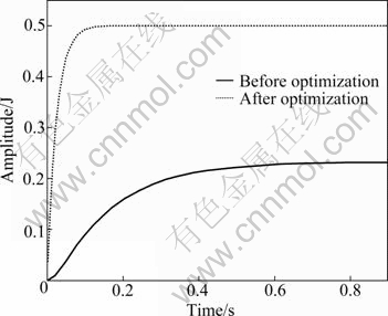
Fig. 2 Step response of steering road feel
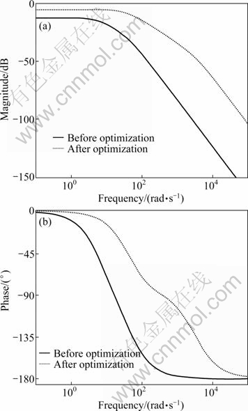
Fig. 3 Bode reponse of steering road feel: (a) Amplitude frequency characteristics of steering road feel (I); (b) Phase frequency characteristics of steering road feel (I)
4.5.2 Single-objective and multiple-constraints
With the Routh criterion and steering portability within [1.2×10⁻⁴, 1.8×10⁻⁴] as the constraint conditions, the best result is X=(1.09, 5.6, 200) when the steering road feel f is maximal. That is, n1=1.09, G=5.6, Ks= 200 N・m/rad.
Figures 4 and 5 depict the simulations results of single-objective and multiple-constrains optimization.
The energy of the steering road feel is 0.005 9 after optimization, compared to 0.001 9 before optimization, and it is 3.1 times greater than it before optimization. According to Figs. 4 and 5, the bandwidth increases and the phase delay decreases after optimization. The result shows that, steering road feel of the novel AFS system can be optimized by adopting the multi-objective genetic algorithm optimization of this objective.
4.5.3 Multiple-objectives and multiple-constraints
With the Routh criterion and steering portability within [1.2×10⁻⁴, 1.8×10⁻⁴] as constraint condition, the best result is X=(0.793, 5, 191), when gf is maximal with n=100. That is, n1=0.793, G=5, Ks=191 N・m/rad.
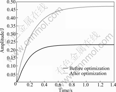
Fig. 4 Step response of steering road feel
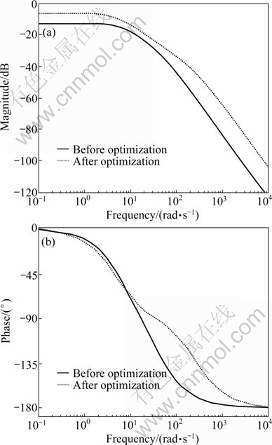
Fig. 5 Bode response of steering road feel: (a) Amplitude frequency characteristics of steering road feel (II); (b) Phase frequency characteristics of steering road feel (II)
Figures 6 and 7 depict the simulations of multiple- objective and multiple-constrains optimization.
After optimization, the energy of the steering road feel is 0.004 4, and before optimization, it is 0.001 9. Additionally, the energy of the steering portability is1.799 8×10⁻⁴ after optimization and is 1.642 5×10⁻⁴ before optimization, so the energy of the steering portability is increased by 9% after optimization. Thereby, the energy of steering road feel is 2.31 times greater after optimization. As is shown in Figs. 6 and 7, the bandwidth increases and the phase delay decreases after optimization. Therefore, the steering road feel of the novel AFS system can be optimized by the genetic algorithm optimization of this objective.

Fig. 6 Step figure of steering road feel

Fig. 7 Bode figure of steering road feel: (a) Amplitude frequency characteristics of steering road feel (III); (b) Phase frequency characteristics of steering road feel (III)
5 Conclusions
1) The novel AFS system with force and displacement coupled control is introduced to extend the steering performance, and it has functions of both the AFS and EPS. Based on the model and the vehicle three-degree of freedom model, the steering road feel, steering portability, and steering stability are put forward and analyzed, which provides the basis for the parameter optimization of the novel AFS system.
2) According to the characteristic of constraint optimization of multivariable function, the parameters of the novel AFS system are optimized using the multi-objective genetic algorithm optimization. The simulation results show that the steering road feel and steering portability can be optimized effectively with multi-objective genetic algorithm. Thus, the optimization method can provide a theoretical basis for the design and optimization of the novel AFS system.
References
[1] CHEN X Q. Optimal control for electrical power-assisted steering system [D]. Canada: University of Windsor, 2005.
[2] ANTHONY W. Innovation drivers for electric power-assisted steering [J]. IEEE Control Systems Magazines, 2003, 23(6): 30-39.
[3] HU J J, LU J, QIN D T. Modeling and simulation of electric power steering system [J]. Journal of Chongqing University Natural Science Edition, 2007, 30(8): 10-13. (in Chinese)
[4] CHEN D L, CHEN L, YIN C L, ZHANG Y. Active front steering during braking process [J]. Chinese Journal of Mechanical Engineering, 2008, 21(4): 64-70.
[5] MAMMAR S, KOEING D. Vehicle handing improvement by active steering [J]. Vehicle System Dynamics, 2002, 38(3): 211-242.
[6] ZHAO W Z, SHI G B, LIN Y, LI Q. Road feeling of electric power steering system based on mixed H2/H∞ control [J]. Journal of Mechanical Engineering, 2009, 45(4): 142-146.
[7] ZHAO X P, LI X, CHEN J, MEN J L. Parametric design and application of steering characteristic curve in control for electric power steering [J]. Mechatronics, 2009, 19(6): 905-911.
[8] KIM D, HWANG S, KIM Hyunsoo. Vehicle stability enhancement of four-wheel-drive hybrid electric vehicle using rear motor control [J]. IEEE Transactions on Vehicular Technology, 2008, 57(2): 727-735.
[9] MICHITSUJI Y, SUDA Y. Running performance of power-steering railway bogie with independently rotating wheels [J]. Vehicle System Dynamics, 2006, 44(suppl): 71-82.
[10] ZHAO W Z, LIN Y, WEI J W, SHI G B. Control strategy of a novel electric power steering system integrated with active front steering function [J]. Science China Technological Sciences, 2011, 54(6): 1515-1520.
[11] WANG R P, YANG G R. Simulation study for assist characteristic of electric power steering [J]. Tractor & Farm Transporter, 2008, 35(4): 93-97. (in Chinese)
[12] LIN Y, SHEN R W, SHI G B. Development of electric control unit in electric power steering system of pure electric power bus [J]. Journal of Jiangsu University Natural Science Edition, 2006, 27(4): 310-313. (in Chinese)
[13] PATRICK S. Numerical simulation of electric power steering (EPS) system [J]. KOYO Engineering Journal English Edition, 2002(16): 52-56.
[14] ZHAO X P, LI X, CHEN J, et al. Parametric design and application of steering characteristic curve in control for electric power steering [J]. Mechatronics, 2009, 19(6): 905-915.
(Edited by DENG Lü-xiang)
Foundation item: Project(51005115) supported by the National Natural Science Foundation of China; Project(KF11201) supported by the Science Fund of State Key Laboratory of Automotive Safety and Energy, China; Project(201105) supported by the Visiting Scholar Foundation of the State Key Laboratory of Mechanical Transmission in Chongqing University, China
Received date: 2011-02-23; Accepted date: 2011-06-27
Corresponding author: ZHAO Wan-zhong, Associate Professor, PhD; Tel: +86-25-84892200-2615; E-mail: zhaowanzhong@126.com

