Article ID: 1003-6326(2005)03-0600-06
Characterization of oxide films formed on magnesium alloys using bipolar pulse microarc oxidation in phosphate solutions
WANG Li-shi(НхБўКА), CAI Qi-zhou(ІМЖфЦЫ),
WEI Bo-kang(ОєІ®їµ), LIU Quan-xin(БхИ«РД)
(State Key Laboratory of Die and Mould Technology,
Huazhong University of Science and Technology, Wuhan 430074, China)
Abstract: The surface morphology and chemical composition of the oxide films formed on pure magnesium and AZ91D alloy in aqueous electrolytes which contained sodium hexafluorinealuminate(Na3AlF6), potassium hydroxide (KOH), sodium hexametahposphate((NaPO3)6), and triethanolamine were investigated by X-ray diffraction(XRD), scanning electron microscope(SEM) and energy dispersive spectroscopy(EDX). The results show that the input of the negative pulse has great influences on the quantity and the appearance of the microdischarges. Three types of pores can be distinguished on the surface of the oxide film and their size ranges are 0.5-1¦Мm, 1-2¦Мm and 4-7¦Мm, respectively. A few microcracks are seen around the large pores. There exists a remarkable fluoride-enriched zone of about 4-6¦Мm for pure magnesium and 3-5¦Мm for AZ91D alloy at the coating/substrate interface.
Key words: magnesium; AZ91D alloy; oxide film; microarc oxidation CLC
number: TG146.2 Document code: A
1 INTRODUCTION
Microarc oxidation(MAO) is a new electrochemical surface treatment technology developed on the basis of the conventional anodizing. The phase composition and structure of MAO oxide films can be easily controlled and improved by modifying the electrolyte composition and process parameters which correspondingly effects the conditions of the plasma discharge at the oxide/electrolyte interface[1, 2]. The mechanism of oxide layer formation during MAO represents a complex combination of conventional anodic oxide film growth with plasma enhanced surface oxidation in microarc discharges regions, leading to fusing and recrystallization of the oxide film[3]. Due to the incorporation of the electrolyte species in the oxide film formation, the types and the quantity of the electrolyte components have great influences on the composition and properties of the oxide films, which is an important research and application area at the present time. Moreover, the structure and morphology of the microdischarges population affect the morphology and performance of the oxide film. Controlling the electrical pulse frequency and waveform to create shorter, yet more energetic, microdischarge events can ensure a better balance between oxidizing and fusing/recrystallizing aspects of the coating formation process. Thus, the high frequency bipolar system is believed to allow three to five times enhancement of the coating deposition rate combined with substantial improvement in the surface layer quality[4]. So, a suitable electrolyte and electrical regime are the two most efficient ways to improve the MAO efficiency and to obtain an anodic film with satisfactory properties for a specific Mg alloy.
In this investigation, specimens of pure magnesium and AZ91D alloy were processed in the electrolyte contained the compounds of the hexafluorinealuminate ions under the conditions of bipolar pulse MAO. The use of hexafluorinealuminate in the electrolyte composition is due to the stability of the electrolyte and it may lead to the formation of hard, heat-resistant phase under the conditions of the microdischarges.
2 EXPERIMENTAL
The sample plates used in this experiment were machined to size of 50mmЎБ30mmЎБ10mm. According to the former vast scale experi-ments, the electrolyte constituents were employed which contained sodium hexafluorinealuminate(Na3AlF6), potassium hydroxide(KOH), sodium hexametahposphate((NaPO3)6), and triethanolamine. The pH value of the electrolyte was in the range of 11-12 before MAO. The homemade power supply could provide bipolar pulses and the duration and amplitude of positive pulses could be controlled independently, while for the negative pulse only the amplitude could be set and its duration was fixed in 200¦Мs. The modifying range of the pulse frequency was 1-2000Hz.
The experiment was conducted using a high frequency(700Hz) bipolar pulse mode and the amplitude of the negative electrical pulse was set in 60V. The controlling mode called step-down current method is shown in Fig.1. This method could make the MAO process more stable and more effective. Big electric current i0 (7-9A/dm2) was used to strike to make the voltage increase to V0 first, then electric current was reduced to i1(4-6A/dm2) and held for some time(t1-t0). When the voltage reached V1, the electric current reduced to i2(0.5-1A/dm2) and then kept for some time (t2-t1). The two MAO processes were operated for 15min respectively. The temperature of the electrolyte was kept below 35Ўж. A stainless steel plate was used as the counter electrode. The coated samples were rinsed in distilled water, dried in hot air and then kept in drying chamber for tests.
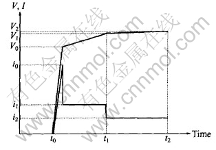
Fig.1 Schematic plan of parameters controlling during MAO process
The coating microstructure and morphology were characterized by optical and scanning electron microscopy(JXA-8800R), observing the structure both parallel to the substrate and also in polished cross-sections. Phase composition was studied by XRD analysis using a D/Max-ўуB diffractometer(CoK¦Б radiation). Depth profiles of the related elements incorporated in the oxide film were determined by energy dispersive X-ray spectrometry(EDX) in the transmission electron microscope.
3 RESULTS AND DISCUSSION
3.1 MAO process characterization
A typical voltage/time curve observed during MAO of the pure magnesium and AZ91D alloy is shown in Fig.2. In the general case, several characteristic areas can be resolved in VЎЄt curve during the MAO process[5, 6]. Region (1) exhibits maximum gradient on the voltage curve and corresponds to a conventional magnesium anodizing process. In region (2), the rate of voltage increase slackens, which indicates a decrease in the oxide film growth rate and oxygen bubbles first appear on the sample surface. In region (3), the rate of voltage increase rises again and this usually corresponds to oxide recrystallization and defect appearance in the film structure. Region (4) begins with intensive oxygen evolution, which creates a background for the onset of plasma micro-discharge phenomena on the sample surface. The characteristic areas of the voltage/time curve between pure Mg and AZ91D alloy is basically similar, but the breakdown and final voltage of the AZ91D alloy is higher than that of the pure magnesium. The breakdown and final voltage are closely related with the characterization of the substrate alloy and the corresponding MAO films. The alloying elements in AZ91D, especially Al, may modify the surface structure, change the passivity conditions[7] and then affect the breakdown voltage and microarc voltage[8].
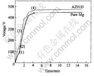
Fig.2 Typical variation of positive voltage amplitude with time
The voltage/current waveform during the coating formation process is shown in Fig.3. Apparently, there exists a Ў°spin spotЎ± in the voltage waveform when the positive rectangular pulse appears. Moreover, there is a large current impact when the pulse polar changes. The electric current steep rising is often observed during the anodizing process of magnesium alloy when the sparking appears, but the mechanism is unclear[9-11].
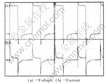
Fig.3 Voltage/current waveform during MAO process
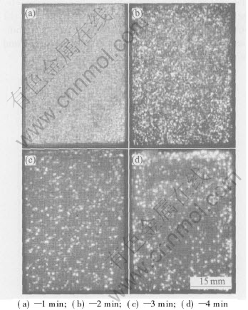
Fig.4 Microdischarge appearance of coating formation process at different stages
The microdischarge population appearance changed apparently during the different stage of MAO. Fig.4 shows the visible sparks images for pure magnesium and AZ91D alloy during MAO process. At the beginning of the process a large number of sparks are in the form of moving discrete blue microdischarges. Then, with the increasing voltage, some of microdischarges become yellow, larger and slower moving. On the transition of the microdischarge appearance, Yerokhin et al[12] believed that it was only an emission spectrum change of the composition phase in the oxide films, rather than the generation of a new type of Ў°microarcЎ± discharge. In fact the discharge seems to remain a glow discharge in its nature. In this experiment, with the input of the negative pulse, the number of the microdischarges decreased, the size became large and the color became yellow abruptly. The changes in the quality and appearance of the microdischarges may be related to the disintegrated gas bubbles formed at the interface between the electrolyte and substrate. According to the theory of contact glow discharge model, the layer growth causes the enlargement of some microdischarges, and the enlargement of the microdischarges with the thickening layer can be explained by decreasing thermal input to the substrate metal from heated gas bubbles. This has the effect of increasing the local gas temperature, causing more intensive electron emission from the cathodic electrolyte-gas interface. As a consequence, more gaseous products are formed and these gases inflat the plasma bubble, which reveals the great effects of the input of the negative pulse on the appearance and quantity of the microdischarges.
3.2 Film morphology
A top view of the MAO films formed on the pure magnesium is shown in Fig.5. Three types of pores can be seen in this film and their size ranges are 0.5-1¦Мm, 1-2¦Мm and 4-7¦Мm, respectively(ўс, ўт, ўу shown in Fig.5(a)). Different pores likely formed at different currents generate in different microplasma channels. Moreover, different types of microdischarge may be result in the formation of different type of pores. In general, the actual size is larger than the micodischarges statistical data presented in the literature[12, 13]. The result may be that the substrate alloy was different and the higher final voltage employed in this experiment leaded to the accumulation of the microdischarge breakdown at the same spot.
Fig.5 Top-view SEM images of oxide films on pure magnesium
In addition, a few cracks can be seen around the large pores(ўф shown in Fig.5(b)). A great number of large pores and the presence of few cracks around them likely lead to its earlier failure during corrosion testing. Generally the microcracks are closely related with the stresses existing in the oxide films. The simplest stress generating mechanism is that arising from the volume ratio of metal to oxide(Pilling-Bedworth ratio, abbreviated as P/B), which is important when ionic current in the oxide is carried predominantly by anions[7, 14]. When the P/B valve of the oxide film is less than 1, surface coating is in tensile stress and probably results in the appearance of the net-like micro-cracks, as shown in Fig.5(b). Moreover, the stress in the oxide film is a sensitive function of the rate of growth and the rate of temperature variant. Under the same conditions, oxides grown rapidly have higher stress than those grown slowly and the deep change of temperature has the great influences on the stress, for example, the microdischarge temperature can rise to 2250Ўж[8] during the period of less than 1ms and its cooling rate can reach 107K/s[12]. The sudden changes of the coating composition and process conditions caused the development of the microcracks in the MAO film.
A closer look at the cross-sectional images in Fig.6 reveals that this particular oxide film is actually composed of three layers, two outer porous layers and an inner barrier layer(ўс, ўт, ўу shown in Fig.6). The barrier layer is likely the most significant portion of the film leading to its corrosion resistance, and it is very important to note that the barrier film doesn¬рt appear to be porous or cracked. The total film thickness for pure magnesium in Fig.6 was 12-15¦Мm, while the inner barrier film was 400nm in thickness.
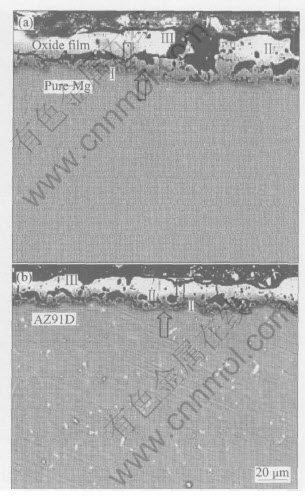
Fig.6 SEM images of cross section of pure magnesium(a) and AZ91D alloy(b)
3.3 Film composition
X-ray diffraction(XRD) pattern of the MAO film on pure magnesium surface reveals only peaks of magnesium substrate, indicating that the film is mainly amorphous or microcrystalline. Similarly, the film formed on AZ91D alloy surface, it is still evident from substrate magnesium peak. At the same time, small peaks of the crystalling MgAl2O4 reveal(see Fig.7).
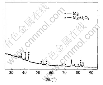
Fig.7 XRD pattern of MAO film formed on surface of AZ91D alloy
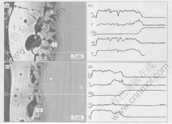
Fig.8 Cross-section images of MAO films formed on pure Mg(a) and AZ91D alloy(c) and their individual line scanning analysis results(b) and (d)
The line scan results of Mg, Al, O, F and P element across the coating and substrates are shown in Fig.8. Apparently there exists a fluoride-enriched zone of about 4-6¦Мm for pure magnesium and 3-5¦Мm for AZ91D alloy at the film/substrate interface with a maximum fluoride concentration(ўс section in Fig.8(a) and ўт section in Fig.8(c)). The enrichment of fluorine ions is at the film/substrate interface, rather than in the outer layer of the film will favoring the healing of defects in the film by blocking the cathodic reaction at these sites[15]. The concentration profile of phosphorus is relatively uniform over the whole cross-section of the MAO film. However, the concentration of aluminum in the coating on pure Mg is larger than that on AZ91D alloy, which induces that for the formation of MAO film the effect of aluminum in electrolyte solution is more evident than that in alloyed aluminum. SONG et al[16] studied the causes which magnesium became more resistant by alloying with aluminum. It was found to be the alumina component of the inner layer of the magnesium hydroxide film becoming the dominant factor in determining the passivity of the surface, presumably by forming a continuous skeletal structure consisting of an amorphous mixture of aluminum and magnesium. In contrast, aluminum ions in electrolyte not only react with the surface, but also integrate in the magnesium hydroxide together with other ions. So the passivation effect of aluminum addition in electrolyte is more evident than that of the addition in magnesium substrate. The concentration of magnesium remains the same in both films, independent of the formation conditions.
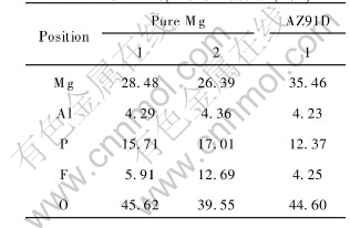
EDX analysis results of different spots in the cross-section surface(see Fig.8(a) and Fig.8(c)) are shown in Table 1. Based on the relative contents of several elements in the oxide films, the possible composition of the oxide film is Mg(OH)2, MgO, MgF2, phosphate and a small amount of Al2O3. The composition of the barrier film is different from that of the outer layer, especially for fluorine content. This suggests that fluoride may play an important role during the course of the initial film formation. Due to the low solubility product of MgF2, it could have a beneficial effect as inhibitor in the sense. In this experiment, the presence of fluoride in the oxide film was the result of the reaction between fluoride cation in the solution and Mg anion in the film. The increasing in local temperature due to sparking will also accelerate the growth of MgF2[17].
Table 1 Concentration of elements in MAO films(mole fraction, %)
The enrichment of fluoride at the interface between the coating and the substrate suggests that the hexafluorinealuminate ion in the electrolyte composition is subjected to hydrolysis with the formation fluorine ion and aluminum hydroxide[18], and the hydrolysis reaction is formula (1). The hydrolysis product fluoride ion reacts with magnesium ion in the electrolyte solution leading to the formation of fluoride-enriched zone at the alloy/solution interface, as shown in formula (2). Thermal decomposition of aluminum and magnesium hydroxide leads to the formation of the magnesium and aluminum oxides in the films, as shown in formulas (3) and (4). Finally MgAl2O4 is formed as shown in formula (5) under the conditions of plasma microdischarges:
AlF3-6+3H2OЎъAl(OH)3+3H++6F-(1)
Mg2++2F-ЎъMgF2(2)
2Al(OH)3ЎъAl2O3+3H2O(3)
Mg(OH)2ЎъMgO+H2O(4)
Al2O3+MgOЎъMgAl2O4(5)
4 CONCLUSIONS
1) The input of the negative pulse greatly affects the quantity and the appearance of the microdischarges. The reasons are related to the disintegrated gas bubbles formed at the interface between the electrolyte and substrate during the period of the input of the negative pulse.
2) Three types of pores can be seen on the surface of the anodic film, and the size ranges are 0.5-1¦Мm, 1-2¦Мm and 4-7¦Мm, respectively. In addition, a few cracks are seen around the large pores. The cracks are caused by the internal stress in the MAO films and its quantity is related with the composition, growth rate and cooling rate of MAO films under continuous sparking.
3) There clearly exists a fluoride-enriched zone of about 4-6¦Мm for pure magnesium and 3-5¦Мm for AZ91D alloy at the film/substrate interface. Comparing the concentration of aluminum between the two films, the effect of aluminum ion in the electrolyte is more remarkable than that of the alloyed aluminum element.
REFERENCES
[1]Yerokhin A L, Nie X, Leyland A, et al. Plasma electrolysis for surface engineering [J]. Surface and Coatings Technology, 1999, 122: 73-79.
[2]XUE Wen-bin, DENG Zhi-wei, LAI Yong-chun, et al. Review of microarc oxidation technique on surface of nonferrous metals [J]. Metal Heat Treatment, 2001(1): 1-3.(in Chinese).
[3]Yerokhin A L, Viktor V V, Ashitkov L V, et al. Phase formation in ceramic coatings during plasma electrolytic oxidation of aluminum alloys [J]. Ceramic International, 1998, 24: 1-6.
[4]Yerokhin A L, Shatrov A, Samsonov V, et al. Fatigue properties of keronite(r) coatings on a magnesium alloy [J]. Surface and Coatings Technology, 2004, 182(1): 78-84.
[5]Khaselev O, Weiss D, Yahalom J. Anodizing of pure magnesium in KOHЎЄaluminate solutions under sparking [J]. Journal of the Electrochemical Society, 1999, 146(5): 1757-1761.
[6]Snizhko L O, Yerokhin A L, Pilkington A, et al. Anodic processes in plasma electrolytic oxidation of aluminum in alkaline solutions [J]. Electrochimica Acta, 2004, 49(13): 2085-2095.
[7]Schmutz P, Guillaumin V, Lillard R S, et al. Influence of dichromate ions on corrosion processes on pure magnesium [J]. Journal of the Electrochemical Society, 2003, 150(4): B99-B110.
[8]Khaselev O, Weiss D, Yahalom J. Structure and composition of anodic film formed on binary Mg-Al alloys in KOH-aluminate solutions under continuous sparking [J]. Corrosion Science, 2001, 43: 1295-1307.
[9]Barbosaa Peixoto D, Knў‰rnschilda G, et al. Electron microscopic studies of anodic oxide films on the AZ91D HP alloy [J]. Materials Research, 2003, 6(1): 103-106.
[10]Mizutani Y, Kim S J, Ichino R, et al. Anodizing of Mg alloys in alkaline solutions [J]. Surface and Coatings Technology 2003, 169-170(2): 143-146.
[11]WU Chu-tsun, LU Fu-hsing. Electrochemical deposition of barium titanate films using a wide electrolytic voltage range [J]. Thin Solid Films, 2001, 398-399(11): 621-625.
[12]Yerokhin A L, Snizhko L O, Gurevina N L, et al. Discharge characterization in plasma electrolytic oxidation of aluminum [J]. J Phys D: Appl Phys, 2003, 36: 2110-2120.
[13]Yerokhin A L, Snizhko L O, Gurevina N L, et al. Spatial characteristics of discharge phenomena in plasma electrolytic oxidation of aluminum alloy [J]. Surface and Coatings Technology, 2004, 177-178(1): 779-783.
[14]YE Kang-min. Metal Corrosion Protection(3rd Edition) [M]. Beijing: Advanced Education Press, 1980. 8-22. (in Chinese)
[15]Cohen S M. Review: preplacements for chromium pretreatments on aluminum [J]. Corrosion, 1995, 51(1): 71-76.
[16]SONG Guang-ling, Atrens A, WU Xian-liang, et al. Corrosion behavior of AZ21, AZ501 and AZ91D in sodium chloride [J]. Corrosion Science, 1998, 40(10): 1769-1791.
[17]Ono S, Kijima H, Masuko N. Microstructure and voltage-current characteristics of anodic films formed magnesium alloy in electrolytes containing fluoride [J]. Materials Transactions, 2003, 44(4): 539-545.
[18]Gnedenkov S V, Khrisanfova O A, Zavidnaya A G, et al. Production of hard and heat-resistant coatings on aluminum using a plasma micro-discharge [J]. Surface and Coatings Technology, 2000, 123(1): 24-28.
(Edited by LI Xiang-qun)
Foundation item: Project(2002ABB051) supported by the Natural Science Foundation of Hubei Province and the Postgraduate Foundation of HUST, China Received date: 2004-06-06; Accepted date: 2004-12-26
Correspondence: WANG Li-shi, PhD candidate; Tel: +86-27-87543876; E-mail: wlshust@sohu.com

