Analysis of influencing factors on suction capacity in seabed natural gas hydrate by cutter-suction exploitation
来源期刊:中南大学学报(英文版)2018年第12期
论文作者:徐海良 孔维阳 胡文港
文章页码:2883 - 2895
Key words:seabed natural gas hydrate; working head; solid-liquid two-phase flow; cutter-suction capacity; influencing factor
Abstract: The mathematical and simulation models of working head in the deep-sea working environment were built to analyze the effects of cutter-suction flow, cutter-head rotating speed, cutting depth and suction port position on the cutter-suction capacity. The efficiency of the cutter-suction is analyzed based on the analysis of the variation law of the solid-phase volume fraction of the flow field, the variation law of the velocity distribution in the flow field and the distribution law of the solid-phase concentration. The results show that the increase of cutter-suction flow can significantly improve the cutter-suction efficiency when it is less than 1000 m3/h. However, when it is more than 1000 m3/h, it is helpless. When the cutter-head rotate speed is within the range of 10–25 r/min, the cutter-suction efficiency stabilizes at about 95%. While the speed is greater than 25 r/min, the cutter-suction efficiency decreases sharply with the increase of cutter-head rotate speed. With the increase of cutting depth, the cutter-suction efficiency first increases and then remains stable and finally decreases. The cutter-suction efficiency remains at about 94% when the suction port position deviation ranges from 0° to 30°, but it has a sharply reduction when the deviation angle is more than 30°.
Cite this article as: XU Hai-liang, KONG Wei-yang, HU Wen-gang. Analysis of influencing factors on suction capacity in seabed natural gas hydrate by cutter-suction exploitation [J]. Journal of Central South University, 2018, 25(12): 2883–2895. DOI: https://doi.org/10.1007/s11771-018-3960-z.

J. Cent. South Univ. (2018) 25: 2883-2895
DOI: https://doi.org/10.1007/s11771-018-3960-z

XU Hai-liang(徐海良), KONG Wei-yang(孔维阳), HU Wen-gang(胡文港)
School of Mechanical and Electrical Engineering, Central South University, Changsha 410083, China
 Central South University Press and Springer-Verlag GmbH Germany, part of Springer Nature 2018
Abstract: The mathematical and simulation models of working head in the deep-sea working environment were built to analyze the effects of cutter-suction flow, cutter-head rotating speed, cutting depth and suction port position on the cutter-suction capacity. The efficiency of the cutter-suction is analyzed based on the analysis of the variation law of the solid-phase volume fraction of the flow field, the variation law of the velocity distribution in the flow field and the distribution law of the solid-phase concentration. The results show that the increase of cutter-suction flow can significantly improve the cutter-suction efficiency when it is less than 1000 m3/h. However, when it is more than 1000 m3/h, it is helpless. When the cutter-head rotate speed is within the range of 10–25 r/min, the cutter-suction efficiency stabilizes at about 95%. While the speed is greater than 25 r/min, the cutter-suction efficiency decreases sharply with the increase of cutter-head rotate speed. With the increase of cutting depth, the cutter-suction efficiency first increases and then remains stable and finally decreases. The cutter-suction efficiency remains at about 94% when the suction port position deviation ranges from 0° to 30°, but it has a sharply reduction when the deviation angle is more than 30°.
Key words: seabed natural gas hydrate; working head; solid-liquid two-phase flow; cutter-suction capacity; influencing factor
Cite this article as: XU Hai-liang, KONG Wei-yang, HU Wen-gang. Analysis of influencing factors on suction capacity in seabed natural gas hydrate by cutter-suction exploitation [J]. Journal of Central South University, 2018, 25(12): 2883–2895. DOI: https://doi.org/10.1007/s11771-018-3960-z.
1 Introduction
The current serious shortage of resources and energy makes the search for new clean energy imminent. After decades of exploration and researching, more and more countries and researchers focus on natural gas hydrate which is referred to as gas hydrate [1]. Deep sea is one of the few areas which have not been explored thus its abundant resources have gaining increasing attention in the twenty-first century [2, 3], among which is the seabed natural gas hydrate collecting. Countries like Germany, Japan, Poland and Korea have carried out the on-land simulation test [4] while the sea trial has also been conducted by OMI consortium, Germany, Canada, American, India, Japan and Korea [5–7]. China has explicitly stated the importance of exploration of the natural gas hydrate in the “12th Five-Year” energy development planning [8] and successfully collected hydrate ore body in the Shenhu waters of the South China Sea in May 2017 [9]. Research work shows that the majority of natural gas hydrate mineral layer is close to the ocean floor, some even exposed on the seabed [10]. For those exposed gas hydrate, based on the working principle of the cutter suction dredger, the study group puts forward a new method for mine gas hydrate—cutter-suction exploitation [11–13]. The principle of cutter-suction exploitation is shown in Figure 1. First, the natural gas hydrate is broken into particles by cutter-head on the mine car. Then the particles are sucked into the pipe and carried to the mid-transferring barn. With the slurry pump the particles are continuously elevated to the sea level to decompose and the waste is discharged to the seabed through the tailing pipe. Studies on the cutter optimization and cutter-suction flow analysis have been carried out by Shanghai Jiaotong University, Wuhan University of Technology and Hohai University [14–16]. A new type of deep-sea mining tool based on cutter-suction dredger has been designed by WU et al [17]. However, due to its complex structure and difficulty in manufacturing, it has not yet been put into practical application. DEKKER et al [18] LIU et al [19] carried out numerical calculations and experimental studies on the complicated flow in cutter-head when soil was dredged by dredgers, and clarified the relationship between cutter rotating speed and pump flow. FANG et al [20] studied the cutter suction flow field of dredger cutter in clear water and obtained the law. WEI et al [21] using differential evolution algorithm to achieve the optimization design for cutter-suction mining system. However, little research has been reported on the exploitation of seabed gas hydrate deposits with the cutter-suction deep-sea mining system, especially the researches on the cutter-suction flow, cutter-head rotating speed, cutting depth, suction port position, cutter-suction efficiency and mechanism of cutter cutting.

Figure 1 Principle diagram of cutter-suction mining system:
Based on the basic principle of solid-liquid two-phase fluid mechanics, numerical simulation in the cutter-head suction flow field is carried out by the researching group to explore the rheological properties and analyze the influence of cutter- suction flow, cutter rotating speed, cutting depth and suction port position on the efficiency of cutter-suction.
2 Model building
2.1 Basic hypothesis
The flow field inside the pipeline of hydraulic lifting system gets more complicated due to the characteristics of natural gas hydrate (solid-phase transforms into gas phase when pressure decreases and temperature increases). The process during which gas hydrate particles decompose into gas makes the solid-liquid two-phase flow (hydrate and seawater) turn into a solid-liquid-gas three-phase flow (methane, hydrate and seawater) [22, 23]. In the experimental research with the gas hydrate broken by cutter-head, the cutter-suction flow field is formed and the hypothesis are put forward as follows:
1) The temperature remains the same in the flow field and there is no heat exchange, so the gas hydrate particles have no phase change during the cutting process.
2) Both the solid and liquid phase can be viewed as continuous phase, and the solid-liquid two-phase flow is considered as incompressible steady flow.
2.2 Governing equation
A mathematical model whose governing equations mainly include momentum, energy and continuity equation is established for the cutter- suction flow field of the cutter-head. Among which the energy equation can be ignored as there is no thermal exchange in the mining process.
The continuity equation is:
 (1)
(1)
where ρm, vm and t stand for mixture density, mixture velocity and time respectively.
The momentum equation is:

 (2)
(2)
where p, g, F, μm and T stands for pressure, acceleration of gravity, internal force, mixed viscosity and temperature, respectively.
Euler-Lagrange method and Euler-Euler method are mainly applied in the numerical simulation of solid-liquid two-phase flow. The Euler-Lagrange method treats liquid phase as continuous phase yet views the solid as discrete phase. Although it simplifies the flow, the interaction between the solid particles in the solid-liquid two-phase flow process is ignored. So it is mainly applied to simulating the scene with low concentration. While Euler-Euler method treats the solid as a continuous medium and views the solid particles as pseudo fluid, which takes the interaction between the solid phase into account. As there is a higher volume fraction of solid for cutter- suction flow filed and a stronger interaction between the solid particles in the research experiment, so Euler-Euler method is preferred rather than Euler-Lagrange method [24, 25].
RNG κ–ε [26] turbulence model is approximated and simplified as shown in follows:

 (3)
(3)


 (4)
(4)
where dj is the jth direction displacement, uj is the jth direction flow speed, ue is the fluid effective viscosity, Gb is the turbulent kinetic energy produced by buoyancy, Gk is the turbulent kinetic energy produced by laminar velocity gradient, αk, αε is the turbulent Prandtl constant, C1, C2 is the empirical constant and ut is the turbulent viscosity.
In the simulation, the main phase is seawater with viscosity of 1.308×10⁻³ Pa·s and density of 1025 kg/m3. And the second phase is the gas hydrate particles with viscosity of 1.72×10⁻⁵ Pa·s. According to South China Sea exploitation experiment [27], the average wet density of seabed deposits is 1900 kg/m3 and gas hydrate mainly exists in the form of type I whose density is 912 kg/m3. According to the formula ρs=SHρg+(1– SH) ρc (SH, ρg stands for saturation, gas hydrate density, seabed deposits density respectively), if saturation is taken as 30% the average density of natural gas hydrate particles is 1673 kg/m3.
2.3 Cutter-suction system parameters
A new method in cutter-suction exploitation for seabed gas hydrate is put forward by XU [11]. Based on the theory of hydraulic transportation and the special conditions for gas hydrate exploitation, combined with hydraulic lifting sea trial at home and abroad [11–13], the parameters of the hydraulic lifting system of natural gas hydrate are obtained after years of researching. Gas hydrate production formula is W=QCv= (Di, vm, Cv stand for pipe diameter, mixture flow velocity, volume concentration, respectively). To achieve the production capacity of 200 t/h, the particle concentration in the lifting hard pipe should be within the range of 8%–12%, the pipe diameter should be more than 300 mm, and the water velocity in the pipe should be three times faster than the free settling velocity and it should be above the critical flow velocity. Free settling velocity calculation formula is ut=
 (ds, ρs, ρI,φ stand for solid particle diameter, solid particle density, liquid density, spherical resistance coefficient respectively). Taking φ=π/4, ds=20 mm, the free settling velocity is 0.574 m/s. Critical flow velocity calculation formula is
 (ρm, ψi, fi stand for mixture density, shape factor, particle proportion of a certain particle diameter, respectively). Suppose particle size is uniform spherical, taking ψi=2.0, so the critical flow velocity is 2.48 m/s. The design parameters for gas hydrate cutter-suction mining system are shown in Table 1.
According to the physical properties of gas hydrate, together with the design method for the cutter-head [14–16] and similar principle, the design parameters for the cutter-head are obtained. The cutter-head 3D sketch and design are shown as follows.
Table 1 Parameters of gas hydrate cutter-suction mining system

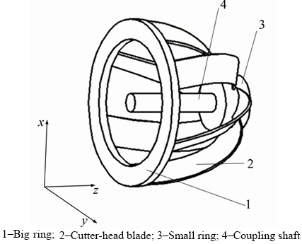
Figure 2 Schematic diagram of cutter-head:
Table 2 Design parameters of cutter-head

2.4 Calculation model
The function of the cutter-head is to break the natural gas hydrate into particles so that they can be sucked into the pipe smoothly. Based on the physical model of the cutter-head, computing model of cutter-suction process is built through the analysis of the mining process. When simulation software Fluent is applied, it is necessary to simplify the process since the cutter-head is in continuous movement. Considering the influence of the cutter teeth on the flow field, the cutter-head blade length is extended to replace the cutter teeth. In the process of simulating, the outside part of the cutter-head is a non-closed area, the calculated field is set to be the area enclosed by the ground and the circle whose diameter is 2.5 times bigger than the average cutter diameter, which is referred to as the area enclosed by curve 4 in Figure 3. In Figure 3, the cutter-head center of the ring is set as the origin of coordinates. The vertical, horizontal and axial directions are regarded as x, y and z axis, respectively. The red arrows represent the liquid- phase inlets while the green ones represent solid- phase inlets. Number 1 represents the pipeline inlet, that is, the calculation model outlet, which is connected to slurry pump by pipeline. The model is divided into mesh by gambit, and cutter-head rotation is simulated by sliding grid. The computational area is divided into two parts, the dynamic area No.2 which contains the cutter-head and the static area No.3. In the dynamic area, the mesh size is evenly divided while in the static area the maximum grid size is limited to 10 mm, the density of the mesh size is controlled by size function. The farther the grid from the dynamic area, the larger it is.

Figure 3 Schematic diagram of simplified calculation model
2.5 Boundary condition
The boundary conditions of the model are listed in Table 3.
Table 3 Boundary condition
3 Results and discussion
According to the working principle of cutting, cutter-suction process was simulated by Fluent software. It assumes that the cutter-head is cutting forward and particles enter into the solid-phase inlet at a certain speed. Considering the various conditions of cutter-suction flow, cutter-head rotating speed, cutter depth and suction port position, the efficiency of solid particles sucked into the pipe is analyzed. By observing the gas hydrate particles concentration and distribution at the outlet, the influencing law of various conditions on the cutter-suction efficiency is also analyzed.
3.1 Influence of cutter-suction flow on cutter- suction capacity
3.1.1 Influence of cutter-suction flow on solid- phase volume fraction at outlet
Different cutter-suction flow was numerically simulated under condition that the cutter-head rotate speed is 20 r/min, the particle size is 20 mm and the cutting depth is 0.5 m. Figure 4 shows the solid- phase volume fraction at outlet and cutter-suction efficiency in different cutter-suction flows. It shows that solid-phase volume fraction decreases with the increase of cutter-suction flow while the cutter- suction efficiency increases. That is because the increase of flow makes the natural gas hydrate particles more likely to be sucked into the pipeline. When the exploiting speed is constant, the increase of flow will inevitably lead to the decline in the solid volume fraction. Over all, the increase of cutter-suction flow effectively improves the cutter- suction efficiency. However, when the cutter- suction flow is more than 1000 m3/h, the cutter- suction efficiency does not improve accordingly. Meanwhile, the excessive cutter-suction flow not only puts a high demanding for slurry pump but also increases the speed of solid-phase and liquid- phase which would result in the wearing of pipeline and slurry pump as well as the hydraulic loss in transportation.
3.1.2 Influence of flow on velocity distribution of cutter-suction flow field
Figure 5 shows scatter diagram of liquid-phase velocity distribution at y=0 cross section with different cutter-suction flow. Suction pipe is located at z=–0.36 m to z=–0.06 m. It can be seen from Figure 5 that the liquid-phase velocity distribution can be divided into two parts, that is, high speed area and low speed area. The high speed area refers to the area in which z<0 with the speed over 3 m/s; and the low speed area refers to the area in which z>0 with the average speed less than 1 m/s. In the suction pipe, the mixed flow velocity is high, while out of it the flow velocity decreases rapidly. The farther the area is away from the suction port, the lower the flow velocity is. Figure 5(a) shows that when cutter-suction flow is 636 m3/h, flow velocity in the pipeline varies within the range of 3–5 m/s. In Figure 5(b) cutter-suction flow is 891 m3/h, flow velocity varies within the range of 4–7 m/s. In Figure 5(c) cutter-suction flow increases to 1018 m3/h, flow velocity is within the range of 4–8 m/s. And in Figure 5(d) cutter-suction flow is 1272 m3/h, flow velocity is within the range of 5–10 m/s. In general, the increase of the cutter-suction flow increases the flow velocity in the pipe effectively, but for the area out of the suction pipe, the flow velocity does not increase obviously. That is because the rapid increase in fluid space makes the flow velocity attenuate sharply.

Figure 4 Solid-phase volume fraction and suction efficiency with different cutter-suction flow
3.1.3 Influence of flow on solid-phase volume concentration distribution in flow field
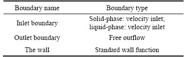
Figure 6(a) shows solid-phase volume concentration distribution along y axis with different cutter-suction flow. It can be seen that with the increase of cutter-suction flow, the distribution range of solid-phase volume concentration along y axis varies slightly, mostly within the range of y=–0.3 m to y=0.5 m. Within that range, the higher the cutter-suction flow is, the lower solid concentration is. It indicates that the cutter-suction ability increases with the higher cutter-suction flow, so there are fewer solid-phase particles left in the area.
Figure 6(b) shows solid-phase volume concentration distribution along z axis with different cutter-suction flow. It can be seen that the solid-phase volume fraction along the z axis decreases with the increase of the cutter-suction flow, which means that the solid-phase particle residua is less in that area. Within the range of z<–0.1 m and z>0.4 m, the solid-phase volume concentration distribution varies greatly with different cutter-suction flows. To be specific, the variation indicates that within the range of z<–0.1 m the lower the cutter-suction flow is, the more easily the solid particles to be accumulated in the pipeline. While within the range of z>0.4 m there are more solid particles spread to the surrounding space with the water flow, which results in decreased efficiency of cutter-suction. Maximum solid volume fraction appears when z=–0.1 m which means there is a sudden change in the cross of solid-phase inlet, that is, the fluid space decreases rapidly and flow velocity increases sharply, which disorders the flow field thus gas hydrate particles accumulate here.

Figure 5 Velocity distribution at y=0 cross section with different cutter-suction flows:
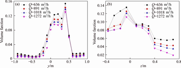
Figure 6 Volume concentration distribution with different cutter-suction flows
3.2 Influence of cutter-head rotating speed on cutter-suction capacity
Suppose cutter speed takes 10, 15, 20, 25, 30, 35 and 40 r/min, respectively, detailed numerical simulation of solid-liquid two-phase flow is carried out under the condition that cutter-suction flow is 1018 m3/h, particle size is 20 mm and mining depth is 0.5 m.
3.2.1 Influence of cutter-head rotating speed on solid volume fraction in calculation model outlet
Figure 7 shows the average value of gas hydrate particle volume fraction in the outlet and cutter-suction efficiency with different cutter-head speeds. It can be seen that both the solid-phase volume fraction and cutter-suction efficiency have a downward trend with the increase of the cutter-head rotating speed. When the speed is lower than 25 r/min, the cutter-suction efficiency is above 95%. However, when the speed increases from 25 to 40 r/min, the cutter-suction efficiency decreases from 95.56% to 72.01% rapidly, which indicates that the excessive cutter-head speed is unfavorable for the exploitation of natural gas hydrate.

Figure 7 Solid volume fraction and cutter-suction efficiency with different cutter-head rotating speeds
3.2.2 Influence of cutter-head rotating speed on velocity distribution within cuter-suction flow field
Figure 8 shows scatter diagram of solid-phase velocity distribution at y=0 cross section with different cutter-head rotational speed. It can be seen that solid-phase particle velocity distribution is similar with different cutter-head speed. When z>0, solid-phase particle velocity mainly distributes in the low speed region. While when z<0, it mainly in the high speed region. The suction port z is within the range of –0.1 m to 0. In Figure 8(a), the speed of the solid-phase particle is within the range of 3– 7 m/s when the cutter-head speed is 10 r/min. In Figure 8(b), the solid-phase particle speed is within the range of 3–7 m/s when the cutter speed is 20 r/min. In Figure 8(c), the solid-phase particle speed is within the range of 2–7 m/s when cutter speed is 30 r/min. And in Figure 8(d), the solid- phase particle speed is within the range of 1–7 m/s when cutter speed is 40 r/min. Overall, the influence of the increase of cutter speed on particle velocity distribution mainly appears near the suction port. The higher cutter-head rotate speed is, the wider solid-phase particle velocity distribution is near the suction port, which indicates that the increase of cutter-head rotate speed makes the flow field fairly well-distributed near the suction port.
Figure 8 Velocity distribution at y=0 cross section with different cutter-head rotate speed:
3.2.3 Influence of cutter-head speed on solid-phase concentration distribution in cutter-suction flow field
Figure 9 shows the color nephogram of solid- phase particle volume concentration with different cutter-head speeds in the cross section where z is 0.2 m. It shows that most of the broken natural gas hydrate particles accumulate on the ground when the cutter-head rotating velocity is low, some of the particles fall down to the ground as they rotate along with the rotating cutter-head (Figures 9(a) and (b)). With the cutter-head speed increases to 30 r/min, some particles no longer fall down to the ground so there are few natural gas hydrate particles accumulate on the ground (Figure 9(c)). Once cutter-head speed reaches 40 r/min, there are much more gas hydrate particles rotating along with the cutter-head blade so accumulated gas hydrate particles at the suction port reduce significantly (Figure 9(d)).
3.3 Influence of cutting depth on cutter-suction capacity
Suppose cutting depth is taken as 0.3, 0.4, 0.5, 0.6 and 0.7 m, respectively, numerical simulation is carried out under the conditions that cutter-suction flow rate is 1018 m3/h, cutter-head speed is 20 r/min and particle size is 20 mm.
3.3.1 Influence of cutting depth on solid phase volume fraction at inlet
Figure 10 shows the solid phase volume fraction and cutter-suction efficiency with different cutting depths. It can be seen that the cutter-suction efficiency first increases then decreases, while the average volume fraction of solid phase increases continuously with the increase of cutting depth. When the cutting depth is increased from 0.3 m to 0.5 m, the volume fraction of solid phase at the outlet increases from 3.94% to 7.96%, and the cutter-suction efficiency increases from 69.96% to the top of 96.89%. When the cutting depth is further increased to 0.7 m, the solid volume fraction increases to 11.08%, while the cutter-suction efficiency is no longer increased. When the cutting depth is increased to 0.8 m, the volume fraction of solid phase increases to 11.46%, and the cutter-suction efficiency drops sharply to 87.15%. Generally speaking, the increase of cutting depth increases the production of solid phase per unit time. However, when the cutting depth is beyond 0.7 m, the amount of broken gas hydrate particles exceeds the capacity of the system so the cutter-suction efficiency declines, meanwhile, the excessive cutting depth would seriously affect the working endurance of the cutter-head.

Figure 9 Contours of solid Z=0.2 m cross section with different cutter-head rotating speeds:

Figure 10 Solid volume fraction at inlet and cutter suction efficiency with different cutting depths
3.3.2 Influence of cutting depth on solid-phase concentration distribution
Figure 11 shows the distribution of solid concentration along y-axis and z-axis with different cutting depths. It shows that the distribution of solid-phase concentration along y-axis is similar with different cutting depths and it mainly within the range of z=–0.2 m to z =0.5 m. When cutting depth is H=0.6 m, the solid concentration is the highest, when cutting depth is H=0.3 m, it is the lowest. The deeper the cutting depth, the higher the solid-phase concentration. When cutting depth is 0.3 m, the maximum solid-phase concentration is 4% along z-axis. When cutting depth is 0.7 m, the solid concentration reaches the maximum of 15% along z-axis, which indicates that as the cutting depth increases, the effect of the cutting head on the fractured gas hydrate particles weakens, therefore more solid phase particles remain in the calculation model. So it is very important to select a reasonable cutting depth to improve the working efficiency in practical mining.
With the increase of the cutting depth, more gas hydrate particles will be produced per unit of time. For further study, the influence of different cutting depth on the distribution of solid phase is analyzed at z=0.2 m section.

Figure 11 Solid phase concentration distribution with different mining depths
Figure 12 shows that with the cutting depth increases, the effect of the cutter-arm on the solid phase gets more pronounced. When cutting depth is 0.3 m, solid particles mainly concentrate on the ground, and there is less interaction between the cutter arm and the solid particles. When cutting depth is 0.4 m, the rotation of the cutter arm would drive some solid particles to rotate. When the cutting depth is 0.6 m, more and more solid-phase particles deposit on the left ground of the cutter as phase particles rotate with the cutter. When the cutting depth reaches 0.7 m, the influence is even more obvious with more solid-phase particles deposit on both sides of the cutter.
3.4 Influence of suction port position on efficiency of cutter-suction
Generally speaking, the position of the suction port is just below the cutter since forward cutting is applied in practical mining and the cutter-arm rotates anticlockwise. When the position of suction port is counterclockwise, it is closer to the cutting surface as shown in Figure 13 in which the red circle represents the suction port and it deviates from vertical line 15°, 30°, 45°, 60°, respectively. Taking the suction port diameter as 250 mm and the number of cutter arms as 6, different suction port positions are numerically simulated.

Figure 12 Contours of solid z=0.2 m cross section with different mining depths:

Figure 13 Different suction port position diagram
As can be seen from Figure 14, when the deviation of the suction port is less than 30°, the volume fraction of the solid phase fluctuates around 8%. With the increase of the deviation angle, the solid volume fraction decreases, the fluctuation amplitude increases, and it reaches the maximum when the suction port deviates from 60°,during which the fluctuation range of the volume fraction of the solid phase is 5%.
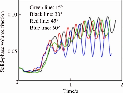
Figure 14 Curves of solid-phase volume fraction in pipe inlet at different suction port positions
Table 4 shows the outlet solid phase average volume fraction and twist-off efficiency at different deviation angles. It can be seen from the table that when the deviation angle of the suction port increases from 0 to 15°, the twist-suction efficiency increases slightly. At 15°–30°, the volume fraction of solid phase at the exit is basically the same, and the efficiency of stranding suction is constantly above 98%. When the deviation angle of suction port continues to increase to 60°, the volume fraction of solid phase at the exit decreases sharply during which the efficiency of stranding suction also drops to 76.77%.
Table 4 Different suction port position exit solid phase average volume fraction and cutter-suction efficiency

4 Conclusions
1) When the cutter-head rotating speed is constant, increasing the cutter-suction flow properly is beneficial to the cutter-suction capability. When the cutter-suction flow is less than 1000 m3/h, gas hydrate particles can not be sucked throughly which would lead to an increasing amount of leakage. When the cutter-suction flow is more than 1000 m3/h, sequentially increasing the flow of the cutter-suction will not effectively improve the cutter-suction capacity and the efficiency remains at about 95%. What’s more, excessive cutter-suction flow not only leads to extra high solid-phase velocity in the pipeline which would intensify the wear between solid particles and pipeline, it also puts an extra high demanding for the slurry pump. Therefore, cutter-suction flow should be set at about 1000 m3/h. It is helpful to select pump and make the pump work well.
2) Generally, the increase of the cutter-head rotate speed produces a pumping effect which is helpful to improve the cutter-suction capacity. However, when the cutter-head rotate speed is more than 25 r/min, the increase of cutter-head rotate speed will lead to the increase of the centrifugal force which would result in sharp decrease of cutter-suction efficiency. When the cutter-head speed increases from 25 r/min to 40 r/min, the cutter-suction efficiency decreases from 95.56% to 72.01%. When the cutter-head speed increased from 10 r/min to 25 r/min, the cutter-suction efficiency decreased slowly, but is still more than 95%. Therefore, the cutter-head rotate speed should be set between 10–25 r/min. It will provide reference for the parameter design of cutter head.
3) When the cutting depth is less than 0.5 m, the cutter-suction efficiency increases with the increase of cutting depth. When the cutting depth is 0.5–0.7 m, the solid-phase volume fraction is high in the inlet of pipe, and the cutter-suction efficiency reaches the highest value of 96%. When the cutting depth is deeper than 0.7 m, as the solid-phase particles spread around with the rotation of the cutter-arm, the cutter-suction efficiency declines. Therefore, the cutting depth should be set between 0.5–0.7 m in practical work.
4) When the suction port position deviation angle is within the range of 0–30°, the cutter- suction efficiency remains at about 97%. When the deviation angle is greater than 30°, the cutter- suction efficiency decreases dramatically. Therefore, the suction port position should not be deviated more than 30°. It can guide the manufacture and installation of suction port.
References
[1] MAKOGON Y F, HOLDITCH S A, MAKOGON T Y. Natural gas-hydrates—A potential energy source for the 21st Century [J]. Journal of Petroleum Science & Engineering, 2007, 56(1–3): 14–31. DOI: https://doi.org/10.1016/ j.petrol.2005. 10.009.
[2] BOSWELL R, COLLETT T S. Current perspectives on gas hydrate resources [J]. Energy & Environmental Science, 2011, 4(4): 1206–1215. DOI:10.1039/C0EE00203H.
[3] TIAN Gong. New sources of energy after shale gas—natural gas hydrate [J]. Natural Gas Industry, 2016, 36(5): 24. (in Chinese).
[4] LI Peng-cheng. Study on hydraulic lifting law of coarse grain vertical pipe [D]. Beijing: Tsinghua University, 2007. (in Chinese). http://kreader.cnki.net/Kreader/CatalogViewPage. aspx?dbCode=cdmd&filename=2008088117.nh&tablename=CDFD9908&compose=&first=1&uid=WEEvREcwSlJHSldRa1FhdkJkVWI2K1hhcHZlNk5VYkpOMDRIODk0T05zTT0=$9A4hF_YAuvQ5obgVAqNKPCYcEjKensW4IQMovwHtwkF4VYPoHbKxJw!!.
[5] YOON C H, PARK J M, KANG J S, et al. Shallow lifting test for the development of deep ocean mineral resources in Korea [C]// Proceedings of the 9th ISOPE Ocean Mining Symposium. Hawaii: International Society of Offshore and Polar Engineers, 2011, 14(5): 149–152. http://www.isope. org/publications/proceedings/ISOPE_OMS/OMS%202011/data/papers/M11-14Yoon.pdf.
[6] PARK S J, YEU T K, HONG S, CHOI J S, KIMH W. Design of a Hardware-in-the-loop Simulation (HILS) of control and monitoring system for deep-seabed manganese nodule miner [C]// Proceedings of the 7th ISOPE Ocean Mining Symposium. Lisbon, Portugal, 2007: 198–203.
[7] ZHU Chao-qi, ZHANG Min-sheng, LIU Xiao-lei, et al. Gas hydrates: Production, Geohazards and Monitoring [J]. Journal of Catastrophology, 2017, 32(3): 51–56. DOI: 10.3969/j.issn.1000-811X.2017.03.010.
[8] LIU Yi-jun. The perspective of natural gas industry chain overall planning in 12th five-year [J]. Natural Gas Industry, 2013, 33(2): 105–109. DOI: 10.3787/j.issn. 1000-0976.2013. 02.021. (in Chinese)
[9] ZHOU Shou-wei, CHEN Wei, LI Qing-ping, ZHOU Jian-liang, SHI He-sheng. Research on the solid Fluidization well testing and production for shallow non-diagenetic natural gas hydrate in deep waterarea [J]. China Offshore Oil and Gas, 2017, 29(4): 1–8. DOI: 10.11935/j.issn.1673- 1506.2017.04.001. (in Chinese)
[10] SONG Yong-chen, YANG Lei, ZHAO Jia-fei. The status of natural gas hydrate research in China: A review [J]. Renewable & Sustainable Energy Reviews, 2014, 31(2): 778–791. DOI: 10.1016/j.rser.2013.12.025.
[11] XU Hai-liang, YANG Fang-qiong, WU Bo. A method of submarine natural gas hydrate cutter-suction: China, 201510568442.0 [P]. 2015-09.(in Chinese).
[12] XU Hai-liang, LIN Liang-cheng, WU Wan-rong, WU Bo. Research on cutter-suction mining method for submarine natural gas hydrate [J]. Acta Scientiarum Naturalium Universitatis Sunyatseni, 2011, 50(3): 48–52. http://www.ix ueshu.com/document/04d418d9d84b7db3318947a18e7f9386.html. (in Chinese)
[13] LI Li, XU Hai-liang, YANG Fang-qiong. Three-phase flow of submarine gas hydrate pipe transport [J]. Journal of Central South University, 2015, 22(9): 3650–3656. DOI: 10.1007/ s11771-015-2906-y.
[14] CHEN Xiao-hua. Analysis of rock cutting for large-sized cutter suction dredger [D]. Shanghai: Shanghai Jiao Tong University, 2012. DOI: 10.3963/j.issn.2095-3844.2013.01. 025. (in Chinese)
[15] LING Liang-yong. Analysis on cutting forces and influence factors of the suction dredger’s cutter [J]. Ship & Ocean Engineering, 2014, 43(4): 156–159. DOI: 10.3963/j.issn. 1671-7953.2014.04.040. (in Chinese)
[16] ZHANG De-xin. Cutting force calculation based on 2-D soild-cutting theory and stress analysis of cutterhead by ANSYS [D]. Nanjing: Hohai University, 2007. DOI: 10.7666/d.y1030679. (in Chinese)
[17] WU Kai-song, JIA Tong-wei, LIAN Dong, YAN Cai-xiu, DAI Mao-lin. Research on design of mining tools of marine gas hydrate reservoirs [J]. Mechanical Science and Technology for Aerospace Engineering, 2017, 36(2): 225–231. DOI: 10.13433/j.cnki. 1003-8728.2017.0211. (in Chinese)
[18] DEKKER M A, KRUYT N P, BURGER M D, VLASBLOM W J. Experimental and numerical investigation of cutter head dredging flows [J]. Journal of Waterway, Port, Coastal and Ocean Engineering, 2003, 129(5): 203–209. DOI: 10.1061/ (ASCE)0733-950X(2003)129:5(203).
[19] LIU Yong-jie, ZHU Han-hua, WU Ying, ZHENG Liang-yan. Numerical simulation of influencing factors on sediment intake of cutter suction dredger [J]. Ship & Ocean Engineering, 2016, 45(4): 166–169. DOI: 10.3963/j.issn.1671-7953.2016. 04.039. (in Chinese)
[20] FANG Yuan, NI Fu-sheng. Numerical simulation of 2-D water flow in and around cutter of a dredger [J]. China Harbour Engineering, 2011, 23(2): 4–7. DOI: 10.3969/j.issn.1003-3688.2011.02.002. (in Chinese)
[21] WEI Xiao, ZHANG Yong-feng, FAN Shi-dong, XIONG Ting. The efficiency optimization of cutter suction dredger’s suction system based on differential envolution [J]. Ship & Ocean Engineering, 2017, 46(2): 143–147. DOI: 10.3963/j.issn. 1671-7953.2017.02.034. (in Chinese)
[22] PADSALGIKAR A. Particle transport in stratified gas-liquid-solid flow [D]. Gradworks, 2015. https://search. proquest.com/docview/1708189909.
[23] LIU Jian-jun, SHAO Zu-liang, ZHENG Yong-xiang. Numerical simulation of the decomposition of natural gas hydrates by depressurization [J]. Journal of Southwest Petroleum University (Science & Technology Edition), 2017, 39(1): 80–90. DOI: 10.11885/j.issn.1674-5086.2016.06.09. 01. (in Chinese)
[24] CHENG X R, LI R N, GAO Y, GUO W L. Numerical research on the effects of impeller pump-out vanes on axial force in a solid-liquid screw centrifugal pump [J]. Iop Conference Series: Materials Science & Engineering, 2013, 33(1): 257–260. DOI: 10.1088/1757-899X/52/6/062008.
[25] CHENG X R, ZHANG N, ZHAO W. Pressure fluctuation features of sand particle-laden water flow in volute of double-suction centrifugal pump [J]. Journal of Drainage and Irrigation Machinery Engineering, 2015, 33(1): 37–42. DOI: 10.3969/j.issn.1674-8530.14.0098.
[26] RICHARDS P J, HOXEY R P. Appropriate boundary conditions for computational wind engineering models using the k-ε turbulence model [J]. Journal of Wind Engineering & Industrial Aerodynamics, 1993, 47(93): 145–153. DOI: 10.1016/0167-6105(93)90124-7.
[27] LU Bo, LI Gan-xian, SUN Dong-huai, HUANG Shao-lin, ZHANG Fu-sheng. Acoustie-physical properties of seafloor sediments from nearshore southeast China and their correlations [J]. Journal of Tropical Oceanography, 2006, 25(2): 12–17. DOI: 10.3969/j.issn. 1009-5470.2006.02.003. (in Chinese)
(Edited by HE Yun-bin)
中文导读
海底天然气水合物绞吸式开采的绞吸能力影响因素分析
摘要:本文根据切削头的结构和工作原理建立数学模型和计算机模型,研究了深海环境下切削头绞吸流场模型中绞吸流量、绞刀转速、挖掘深度和吸口位置对绞吸能力的影响。通过分析绞吸流场的出口固相体积分数变化规律、流场速度分布变化规律、固相浓度分布规律,间接分析了绞吸效率。结果表明:在1000 m3/h绞吸流量内增加绞吸流量能够明显有效地提高绞吸的效率,当超过1000 m3/h时,绞吸效率不再提高,维持在一个相对较高的稳定水平。当绞刀转速在10~25 r/min范围内时,绞吸效率稳定在95%左右的较高水平,当转速大于25 r/min时,绞刀转速增加,绞吸效率降低。当绞刀的挖掘深度低于0.5 m时,绞吸效率随着挖掘深度的增加而增加,在0.5~0.7 m之间时,管道入口固相体积分数较高,绞吸效率也达到了最高值,当大于0.7 m时,绞吸效率随着挖掘深度的增加反而降低。当吸口位置偏离角度为0~30°时,切削头绞吸效率在94%以上且差别不大,当偏离位置大于30°时,切削头绞吸效率急剧下降。
关键词:海底天然气水合物;切削头;固液两相流;绞吸能力;影响因素
Foundation item: Project(51775561) supported by the National Natural Science Foundation of China; Project(20130162110004) supported by the National Doctoral Foundation of China
Received date: 2017-05-18; Accepted date: 2018-03-31
Corresponding author: XU Hai-liang, PhD, Professor; Tel: +86-15116281589; E-mail: xuhailiang@csu.edu.cn

