AZ31镁合金无针搅拌摩擦点焊接头的显微组织与性能
来源期刊:中国有色金属学报(英文版)2019年第11期
论文作者:杨夏炜 冯武渊 李文亚 董秀荣 徐雅欣 褚强 姚朔天
文章页码:2300 - 2309
关键词:无针搅拌摩擦点焊;AZ31镁合金;力学性能;断裂机理
Key words:probeless friction stir spot welding; AZ31 alloy; mechanical properties; fracture mechanism
摘 要:采用无针搅拌摩擦点焊工艺,在没有加中间层锌的条件下,对厚度为1.8 mm的AZ31镁合金搭接接头进行焊接。采用不同的搅拌头旋转速度与停留时间,研究工艺参数对接头显微组织和力学性能的影响。AZ31镁合金的无针搅拌摩擦点焊接头的显微组织可以分为搅拌区、热力影响区和热影响区。随着转速和停留时间的增加,搅拌区深度逐渐增大,钩状缺陷从两块板的界面处延伸至上板表面,接头的拉剪强度以及断裂模式(界面剪切和拔出断裂)均与钩状缺陷的形式密切相关。当搅拌头转速为1180 r/min、停留时间为9 s时,接头的拉剪强度达到最大值,为4.22 kN。上薄板显微硬度值及其波动明显高于下薄板的。
Abstract: The AZ31 magnesium alloy with a thickness of 1.8 mm was welded by the probeless friction stir spot welding process without Zn interlayer. The influence of process parameters on joint microstructure and mechanical properties was investigated by using different rotating speeds and dwell time. Microstructure of joints is divided into three regions: stir zone, thermomechanically- affected zone and heat-affected zone. With the increase of rotation speed and dwell time, the depth of stir zone gradually increases, and hook defects extend from the interface of two plates to the surface of the upper plate. The tensile shear strength of joints and two fracture modes (shear fracture and plug fracture) are closely related to hook defects. The maximum tensile shear strength of the joint is 4.22 kN when rotation speed and dwell time are 1180 r/min and 9 s, respectively. Microhardness value and its fluctuation in upper sheet are evidently higher than those of the lower sheet.
Trans. Nonferrous Met. Soc. China 29(2019) 2300-2309
Xia-wei YANG, Wu-yuan FENG, Wen-ya LI, Xiu-rong DONG, Ya-xin XU, Qiang CHU, Shuo-tian YAO
Shaanxi Key Laboratory of Friction Welding Technologies, State Key Laboratory of Solidification Processing, Northwestern Polytechnical University, Xi’an 710072, China
Received 17 January 2019; accepted 18 September 2019
Abstract: The AZ31 magnesium alloy with a thickness of 1.8 mm was welded by the probeless friction stir spot welding process without Zn interlayer. The influence of process parameters on joint microstructure and mechanical properties was investigated by using different rotating speeds and dwell time. Microstructure of joints is divided into three regions: stir zone, thermomechanically- affected zone and heat-affected zone. With the increase of rotation speed and dwell time, the depth of stir zone gradually increases, and hook defects extend from the interface of two plates to the surface of the upper plate. The tensile shear strength of joints and two fracture modes (shear fracture and plug fracture) are closely related to hook defects. The maximum tensile shear strength of the joint is 4.22 kN when rotation speed and dwell time are 1180 r/min and 9 s, respectively. Microhardness value and its fluctuation in upper sheet are evidently higher than those of the lower sheet.
Key words: probeless friction stir spot welding; AZ31 alloy; mechanical properties; fracture mechanism
1 Introduction
With the increasing importance of lightweight design requirements in aviation, automobile and other fields, magnesium alloys and other lightweight alloys [1-3], with their high specific strength, good damping capacity and easy recycle, have found an increasingly wide utilization in those fields [4-6]. Therefore, the reliability and high efficiency of magnesium alloy connection technology are very important for its long-term service. As a common welding method, spot welding has also received wide attention.
At present, the commonly-used spot welding methods of magnesium alloy mainly include resistance spot welding, conventional friction stir spot welding, refill friction stir spot welding etc. The advantages of resistance spot welding are low cost, high speed (short process time) and good automation [7]. However, the pores and cracks often occur in the resistance spot welding joints [8,9]. LIU et al [8] found that the treatment of surface produced a uniform surface with lower contact resistance, which resulted in higher shear strength because of lower content of internal nugget porosity. Friction stir spot welding (FSSW) is a solid-state welding technique that is a derivative of friction stir welding, and it is free of the defects commonly associated with fusion spot welding [10-13]. However, in the conventional FSSW, many studies have indicated that keyhole and hook defects reduced joint properties such as tensile shear strength and fatigue strength [14]. Therefore, in order to eliminate the keyhole, another derivative of friction stir welding, refill FSSW (RFSSW), was developed. SHEN et al [15] found that volume defects, such as incomplete refilling and lack of mixing, can be observed at the sleeve retracting path due to inappropriate welding parameters. By contrast, the tool system used in RFSSW is complicated and mainly consists of three parts [16].
Probeless FSSW (P-FSSW) is also a derivative of friction stir spot welding developed by BAKAVOS et al [17,18] to eliminate the keyhole. There have been a lot of research on the process, performance and material flow of the P-FSSW of aluminum alloy [19,20]. For magnesium alloys, XU et al [21] chose Zn as the interlayer material with the aim of realizing P-FSSW of Mg alloy. They pointed out that the Zn interlayer reacted with the Mg substrate to form Mg-Zn intermetallic and promote the bonding between sheets, thereby eliminating the hook defect and increasing the bonding area of the joint. However, the reason for adding Zn was that it cannot be welded without adding Zn, and the selected plunge depth was very high. One reason was that the selected tool had no grooves on the shoulder. The studies have shown that the grooves on the shoulder can enhance the material flow in the stir zone and increase the joint fracture load [22]. Therefore, by selecting special tools and the appropriate process parameters, it is possible to achieve the adhesion of the P-FSSW of magnesium alloy in the absence of a magnesium interlayer.
In this study, AZ31 magnesium alloy was chosen as the material to investigate the microstructure and properties of P-FSSW without Zn interlayer. The influence of different parameters (rotation speed and dwell time) on the microstructure of joint was investigated. The relationship between the microstructure characteristic (depth of stir zone and hook angle) and the tensile shear properties of joint was studied. In addition, the fracture mechanism of joint was also investigated in detail.
2 Experimental
In this study, 1.8 mm-thick sheets of AZ31 Mg alloy were lap-welded with P-FSSW. A probeless tool with a shoulder diameter of 15 mm was made of H13 steel. Three involute grooves of the tool were machined on the shoulder surface, which is same as those in our previous study [19,23]. The schematic illustration of the experimental configuration and the shoulder surface of tool is shown in Fig. 1. In order to investigate the variation of the joint structure, different process parameters were used, as given in Table 1. The macro- and microstructures of the joint were studied with an optical microscope (OM). Specimens for microstructure examination were sectioned through the center of the joints (shown in Fig. 2(a)). After being ground and polished, the specimens were etched with saturated picric acid reagent (4.2 g picric acid, 10 mL glacial acetic acid, 10 mL H2O and 70 mL of 95% ethanol). For tensile shear tests, specimens were produced using two 65 mm × 30 mm coupons with an overlap length of 30 mm (shown in Fig. 2(b)) and were tested on a tensile testing machine for each welding parameter at a cross-head speed of 1 mm/min. The fracture features were analyzed with a scanning electron microscope (SEM).
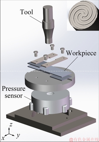
Fig. 1 Schematic illustration of experimental configuration and shoulder surface of tool
Table 1 Process parameters of P-FSSW
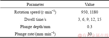

Fig. 2 Schematic diagrams of metallographic (a) and tensile (b) specimens
3 Results and discussion
3.1 Typical macro- and microstructure of joints
Figure 3 reveals the representative cross-sectional micrographs of P-FSSWed joint of AZ31 magnesium alloy. As shown in Fig. 3(a), it can be seen that there are three typical zones: stir zone (SZ), thermomechanically- affected zone (TMAZ) and heat-affected zone (HAZ), which are similar to the P-FSSWed joint of aluminum alloy [24]. During the welding process, the stir zone experiences the maximum high-temperature heat cycle and plastic deformation, dynamic recrystallization occurs and the grains are refined. Subsequently, the grains grow at high temperatures to different sizes, as shown in Fig. 3(b). The average grain size is 10 μm, which is significantly less than that of base metal (25 μm). The TMAZ is formed by the plastic flow of the plastic material around SZ under the shear stress of the tool. The average grain size of TMAZ which is mainly composed of small equiaxed grains and partially deformed grains is 15 μm, slightly larger than that of the stir zone, as shown in Fig. 3(c) (enlarged region f). As magnesium alloys have fewer slip systems, lower recrystallization temperature and stacking fault energy, they are more likely to appear dynamic recrystallization when experiencing high temperatures and large plastic deformation [25], which may be the main reason for the occurrence of large amounts of recrystallized equiaxed grains in TMAZ. As shown in enlarged region g in Fig. 3(c), the HAZ which is only affected by the welding heat cycle is composed of irregular grains and some equiaxed grains. Compared with the base metal, the average grain size (about 21 μm) of the HAZ is slightly reduced. This indicates that the peak temperature of HAZ may exceed the recrystallization temperature of AZ31 magnesium alloy (473 K), so partial recrystallization occurs, making the grain size slightly reduced. Similar phenomena can be found in the FSW joint of AZ31 magnesium alloy [26].
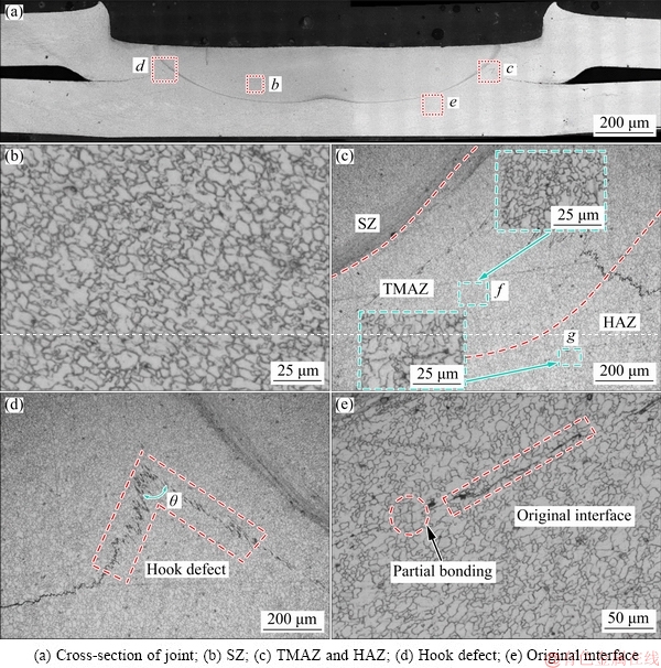
Fig. 3 OM images of P-FSSWed Mg alloy joint (950 r/min, 15 s)
There are two geometric and metallurgical defects in the joint. One of the defects is the hook defect, which exists in the TMAZ at the interface of upper and lower sheets, as shown in Fig. 3(d). Its shape is inverted V, and its angle θ varies with different welding parameters. The hook defect is the weak connection and will lower the mechanical properties. Another metallurgical defect, partial bonding, can also be seen in Fig. 3(e). Part of the initial interface is joined near the centre of joint, forming fine grains due to recrystallization on the boundaries, while the other part is not joined due to the oxide inclusion [23].
3.2 Effect of welding parameters on macro-morphology
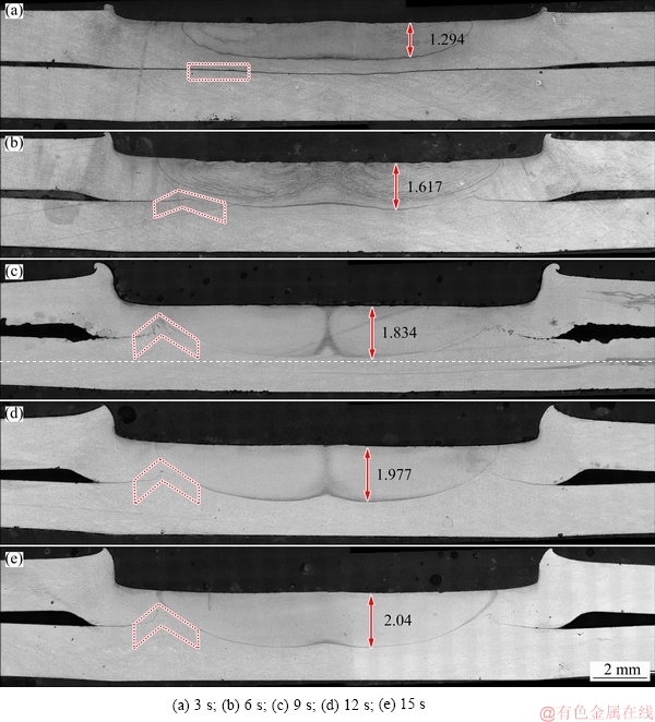
Fig. 4 Macrostructures of P-FSSWed joints with different dwell time at rotation speed of 950 r/min
The macrographs of the cross-section of the joint under different dwell time of 3-15 s at the rotation speed of 950 r/min are shown in Fig. 4. It can be seen that, with the increase of dwell time, the depth of SZ is significantly increased from 1.294 to 2.04 mm, while the angle of hook defect is also decreased. At the same rotation speed of tool, the heat input of the P-FSSW mainly depends on the dwell time. When the dwell time is relatively short (as shown in Fig. 4(a)), there is not enough heat input to soften the material in the SZ, and the SZ concentrated in the upper sheet is shallow. With the increase of dwell time, as shown in Figs. 4(b-d), the increase of heat input boosts the plasticized material in the stir zone and improves the material flow. Under the action of tool, the width and depth of stir zone develop better, and the original interface of upper sheet and lower sheet fades away. When the dwell time increases further, as shown in Fig. 4(e), the increment speed of the width and depth of the stir zone slows down. Our previous research has found that the stir zone edge angle is related to process parameters, being initially proportional to dwell time, reaching a plateau of 45° [20]. It is also found that the depth and width of stir zone have stable values under the specified diameter of the shoulder.
However, it can also be seen that the hook defect angle θ decreases with the increase of dwell time, gradually changing from obtuse angle to acute angle. On one hand, the plasticized materials of the upper plate flows downward and squeezes the plasticized materials of the outer side of the stir zone of the lower plate. On the other hand, the plasticized material of top surface flows inward along the groove of the shoulder continuously driven by the rotation and plunge [26]. This reduces the pressure on the outside of the top surface, and causes the extruded material of lower sheet to flow upward to balance the stress. The longer the dwell time is, the more pronounced the trend is and the smaller the hook angle is.
In order to investigate the effect of different rotation speeds on the macrostructure of joint, the macrographs of the cross-section of the joint at same dwell time of 3 and 15 s and rotation speed of 950 and 1180 r/min are shown in Fig. 5. It can be found that the increase of rotation speed makes the width and depth of stir zone increase obviously at the same dwell time, especially for dwell time of 3 s (as shown in Figs. 5(a) and (b)). This is because the increase of rotation speed can make up for the shortness of heat input caused by the short dwell time and increase the interface connection effect. On the other hand, the increase of rotation speed also increases the shear stress on the plasticized material by the tool and enhances the flow of the plasticized material, which causes hook angle to decrease faster. This phenomenon becomes more obvious with the longer dwell time (as shown in Figs. 5(c) and (d)). In order to visually demonstrate this phenomenon, the statistical results of stir zone depth and hook angle under different parameters are shown in Fig. 6. As can be seen from Fig. 6 that, with the increase of dwell time, the depth of stir zone increases, while the Hook angle decreases.
3.3 Effect of welding parameters on mechanical properties
3.3.1 Tensile shear strength
The change of tensile shear strength of P-FSSWed joints with process parameters is shown in Fig. 7. The maximum tensile shear strength of the joint appears at rotation speed of 1180 r/min and dwell time of 9 s, which is 4.22 kN. It can be found that the tensile shear strength of the joint increases with the increase of dwell time (except 3 s which is failure to form joint) when the rotation speed is 950 r/min. The extension of dwell time from 6 to 15 s results in an increase of 0.37 mm in the depth of stir zone and an increase of 2.69 kN in the joint strength (Fig. 6(a)). This additional dwell time provides more time for the stir zone to better development in thickness direction, resulting in a stronger joint [24]. Therefore, at a low rotation speed, the tensile shear strength of the joint is mainly affected by the size of the stir zone, in other word the heat input.
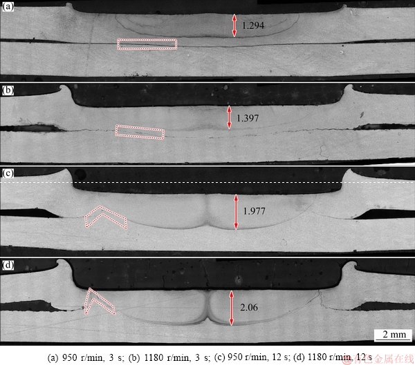
Fig. 5 Macrostructures of P-FSSWed joints with special rotation speeds and dwell time
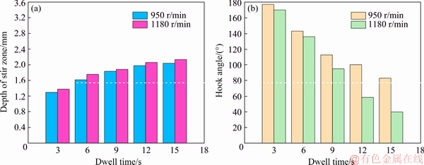
Fig. 6 Statistical results of stir zone depth (a) and hook angle (b) under different process parameters

Fig. 7 Changes of tensile shear strength with dwell time at rotation speed of 950 (a) and 1180 r/min (b)
When the rotation speed is increased to 1180 r/min, with the increase of dwell time, the tensile shear strength of the joint increases first and then decreases gradually. The initial increase in tensile shear strength is also due to the increase in heat input resulting in the expansion of the stir zone to form a better connection, which is consistent with the rotation speed at 950 r/min. However, the decrease of tensile shear strength of joint is related to the hook angle when the dwell time exceed 9 s. It can be seen from Fig. 6(b) that when the dwell time is longer than 9 s, hook angle is still significantly reduced, which means hook defects are more sharp and closer to the upper surface and the effective thickness of top sheet decreases quickly. The hook defect acts as a crack nucleation site, so a crack can nucleate and grow in top sheet under small loads when the defect angle is less than 90°. In addition, the sample orientation has a deflection under loads, which makes the normal force larger to crack along the top sheet more easily. Therefore, at high rotation speed, the hook angle has a significant impact on the tensile shear strength of the joint.
3.3.2 Fracture mechanism
The macrographs of failure samples reveal three distinct facture modes, as shown in Fig. 8. The first one is interfacial shear which is called mode I (shown in Fig. 8(a)) and the second one is pull-out fractures, which is called mode II (shown in Fig. 8(d)) [27]. Figures 8(b) and (c) show the transitional phases of mode I and mode II, which exist simultaneously and are called mixed mode. In mode I, the joint is divided into two parts from the interface, which is caused by the crack originating from the outer edge of hook and extending along the interface of the two sheet. In mode II, the hook angle changes from obtuse angle to acute angle, and the crack extends from the outer edge of hook to the upper surface of the joint. The result of this mode is that the entire stir zone is pulled out and still attached to the lower sheet. In the mixed mode, part of the stir zone is pulled out, and at the same time, the crack extending at the interface makes the joint divided into two parts.
The occurrence of different fracture modes is closely related to the different geometric features of hook defects. Figure 9 shows the schematic cross-section of the failure process of the joint under different fracture modes. The red dashed line and solid line represent stir zone and hook defect, respectively. The light blue area represents the cavity left at the center of the joint after the stir zone is pulled out. When hook angle is obtuse, its height is lower and its direction is consistent with the tensile direction, as shown in Fig. 9(a). Under shear stress, it is easy to crack from the hook defect and along the interface, so the joint strength is weak. When the hook angle is acute, as shown in Fig. 9(c), the highest point of hook defect is very close to the top surface and outer edge of the hook defect is almost perpendicular to the tensile direction. When the joint is stretched, the hook defect in the right side is first cracked by tensile stress and extends to the top surface, causing the stir zone to be pulled out. However, the hook defect in the left side is subjected to compression stress. Since the root of hook is narrow and the stress concentration occurs in the root, the hook in the right side breaks in the upper plate. Finally, the crack on the right side rapidly extends along the top surface to pull out the entire joint from the upper plate. Mixed mode (as shown in Fig. 9(b)) occurs when the hook angle is around 90°. At the hook defect in the right side, the crack extends along the hook toward the top surface to pull out the stir zone, which is consistent with the mode II. Meanwhile, the crack at the hook defect on the left extends along the hook toward the bottom of stir zone, which is consistent with the mode II. The joint breaks along the interface and only small part is pulled out.
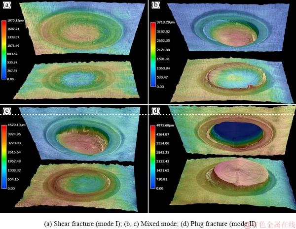
Fig. 8 Fracture modes
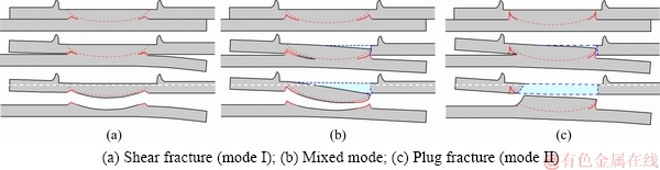
Fig. 9 Schematic illustrations of fracture process
Figure 10 shows the typical fracture structure under different fracture modes. There is a change of fracture morphology among three failure modes. As the heat input increases, failure originates at the hook defect and shifts further away from the interface (mode I), through the mixed mode, towards the surface of top sheet (mode II). As can be seen from Figs. 10(a-c), the crack of interface shear fracture extends along the direction of material flow. With the increase of heat input, the curvature of the groove is also larger, which indicates that the material flow is more sufficient. In addition, it can be seen from Fig. 10(a1), (b1) and (c1) that the number of dimples is significantly increased, which also means that the more the material flows, the better the joint bonding is. It is worth noting that obvious cracks can be found in Fig. 10(d1). This crack is generated by the part of the hook defect broken in mode II.
3.3.3 Microhardness
Figure 11 shows the microhardness distribution of the cross section of the upper and lower sheets along the width direction with different process parameters. As shown in Fig. 11, the microhardness present with fluctuating character. The microhardness value of the cross section of the upper sheet is evidently higher than that of the lower sheet. And the extent of microhardness fluctuation of upper sheet is also evidently larger than that of the lower sheet. When the dwell time is fixed at 6 s, the microhardness value of the cross section of the upper sheet at the rotation speed of 950 r/min is higher than that at the rotation speed of 1180 r/min, especially in the nugget center. However, the microhardness value of the cross section of the lower sheet at the rotation speed of 950 r/min is slightly higher than that at the rotation speed of 1180 r/min.
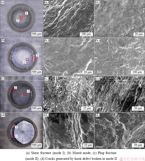
Fig. 10 Fractographs of different facture modes in bottom sheets
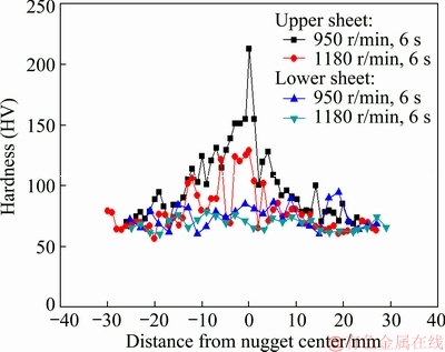
Fig. 11 Microhardness of joint with different process parameters
4 Conclusions
(1) The AZ31 magnesium alloy with a thickness of 1.8 mm was welded by the probeless friction stir spot welding process without Zn interlayer. The tool with grooves can effectively improve material flow.
(2) Three typical zones in the P-FSSWed joint: the stir zone, the thermo-mechanically affected zone and the heat affected zone, are observed, which contain fine recrystallized grains, small equiaxed and partially- deformed grains, and irregular and some equiaxed grains, respectively.
(3) The tensile shear strength is strongly affected by the hook angle. When the hook angle is around 90°, the tensile shear strength reaches its maximum. The maximum tensile shear strength of the joint appears at rotation speed of 1180 r/min and dwell time of 9 s, which is 4.22 kN.
(4) The macrographs of failure samples reveal three distinct fracture modes: interfacial shear, mixed mode and pull-out fracture. The fracture mode changes significantly with the change of hook defect.
(5) When the dwell time is 6 s, the microhardness of the cross section of the upper sheet at rotation speed of 950 r/min is larger than that at 1180 r/min, especially in the nugget center zone. However, the microhardness of the cross section of the lower sheet at rotation speed of 950 r/min is slightly higher than that at 1180 r/min.
References
[1] LIU Xuan, YIN Si-qi, ZHANG Zhi-qiang, LE Qi-chi, XUE Ji-lai. Effect of limestone ores on grain refinement of as-cast commercial AZ31 magnesium alloys [J]. Transactions of Nonferrous Metals Society of China, 2018, 28(6): 1103-1113.
[2] WU Yi-ping, XIONG Han-qing, JIA Yu-zhen, XIE Shao-hui, LI Guo-feng. Microstructure, texture and mechanical properties of Mg-8Gd-4Y-1Nd-0.5Zr alloy prepared by pre-deformation annealing, hot compression and ageing [J]. Transactions of Nonferrous Metals Society of China, 2019, 29(5): 976-983.
[3] MOHAMMADI F D, JAFARI H. Microstructure characterization and effect of extrusion temperature on biodegradation behavior of Mg-5Zn-1Y-xCa alloy [J]. Transactions of Nonferrous Metals Society of China, 2018, 28(11): 2199-2213.
[4] GUO L L, FUJITA F. Effect of deformation mode, dynamic recrystallization and twinning on rolling texture evolution of AZ31 magnesium alloys [J]. Transactions of Nonferrous Metals Society of China, 2018, 28(6): 1094-1102.
[5] CHU Chen-liang, HU Zhi, LI Xiao, YAN Hong, WU Xiao-quan, MAI Yuan-lu. Evolution and distribution of Al2Sm phase in as-extruded AZ61-xSm magnesium alloys during semi-solid isothermal heat-treatment [J]. Transactions of Nonferrous Metals Society of China, 2018, 28(7): 1311-1320.
[6] WANG Xiao-yong, SONG Da-qian, YIN Shi-qiang, LIU Dong-yang. Microstructures and mechanical properties of metal inert-gas arc welded Mg-steel dissimilar joints [J]. Transactions of Nonferrous Metals Society of China, 2015, 25(8): 2533-2542.
[7] BABU N K, BRAUSER S, RETHMEIER M, CROSS C E. Characterization of microstructure and deformation behaviour of resistance spot welded AZ31 magnesium alloy [J]. Materials Science and Engineering A, 2012, 549(7): 149-156.
[8] LIU L, ZHOU S Q, TIAN Y H, FENG J C, JUN J P, ZHOU Y N. Effects of surface conditions on resistance spot welding of Mg alloy AZ31 [J]. Science and Technology of Welding and Joining, 2013, 14(4): 356-361.
[9] WANG Y R, FENG J C, ZHANG Z D. Microstructure characteristics of resistance spot welds of AZ31 Mg alloy [J]. Science and Technology of Welding and Joining, 2013, 11(5): 555-560.
[10] YANG Xia-wei, LI Wen-ya, LI Hong-yu, YAO Shuo-tian, SUN Yi-xuan, SUN Yi-xian, MEI Lu. Microstructures and microhardness for sheets and TIG welded joints of TA15 alloy using friction stir spot processing [J]. Transactions of Nonferrous Metals Society of China, 2018, 28(1): 55-65.
[11] DONATUS U, THOMPSON G E, MOMOH M I, MALEDI N B, TSAI I T, FERREIRA R O, LIU Z. Variations in stir zone and thermomechanically affected zone of dissimilar friction stir weld of AA5083 and AA6082 alloys [J]. Transactions of Nonferrous Metals Society of China, 2018, 28(12): 2410-2418.
[12] ZHAO Hong-yun, YU Ming-run, JIANG Zhi-hua, ZHOU Li, SONG Xiao-guo. Interfacial microstructure and mechanical properties of Al/Ti dissimilar joints fabricated via friction stir welding [J]. Journal of Alloys and Compounds, 2019, 789: 139-149.
[13] ZHOU L, LI G H, ZHANG R X, ZHOU W L, HE W X, HUANG Y X, SONG X G. Microstructure evolution and mechanical properties of friction stir spot welded dissimilar aluminum-copper joint [J]. Journal of Alloys and Compounds, 2019, 775: 372-382.
[14] JORDON J B, HORSTEMEYER M F, DANIEWICZ S, BADARINARAYAN H, GRANTHAM J. Fatigue characterization and modeling of friction stir spot welds in magnesium AZ31 Alloy [J]. Journal of Engineering Materials and Technology, 2010, 132(4): 041008.
[15] SHEN Zhi-kang, YANG Xin-qi, ZHANG Zhao-hua, CUI Lei, LI Tie-long. Microstructure and failure mechanisms of refill friction stir spot welded 7075-T6 aluminum alloy joints [J]. Material Design, 2013, 44: 476-486.
[16] TIER M D, ROSENDO T S, SANTOS J F D, HUBER N, MAZZAFERRO J A, MAZZAFERRO C P, STROHAECKER T R. The influence of refill FSSW parameters on the microstructure and shear strength of 5042 aluminium welds [J]. Journal of Materials Processing Technology, 2013, 213(6): 997-1005.
[17] BAKAVOS D, PRANGNELL P B. Effect of reduced or zero pin length and anvil insulation on friction stir spot welding thin gauge 6111 automotive sheet [J]. Science and Technology of Welding and Joining, 2009, 14(5): 443-456.
[18] BAKAVOS D, CHEN Y C, BABOUT L, PRANGNELL P. Material interactions in a novel pinless tool approach to friction stir spot welding thin aluminum sheet [J]. Metallurgical and Materials Transactions A, 2011, 42(5): 1266-1282.
[19] CHU Q, LI W Y, YANG X W, SHEN J J, VAIRIS A, FENG W Y, WANG W B. Microstructure and mechanical optimization of probeless friction stir spot welded joint of an Al-Li alloy [J]. Journal of Materials Science and Technology, 2018, 34(10): 1739-1746.
[20] LI W Y, CHU Q, YANG X W, SHEN J J, VAIRIS A, WANG W B. Microstructure and morphology evolution of probeless friction stir spot welded joints of aluminum alloy [J]. Journal of Materials Processing Technology, 2018, 252: 69-80.
[21] XU R Z, NI D R, YANG Q, LIU C Z, MA Z Y. Pinless friction stir spot welding of Mg-3Al-1Zn alloy with Zn interlayer [J]. Journal of Materials Science and Technology, 2016, 32(1): 76-88.
[22] LIU Zhen-lei, CUI Hu-tao, JI Shu-de, XU Min-qiang, MENG Xiang-chen. Improving joint features and mechanical properties of pinless fiction stir welding of alcald 2A12-T4 aluminum alloy [J]. Journal of Materials Science and Technology, 2016, 32(12): 1372-1377.
[23] YANG Xia-wei, FENG Wuan-yuan, LI Wen-ya, XU Ya-xin, CHU Qiang, MA Tie-jun, WANG Wei-bing. Numerical modelling and experimental investigation of thermal and material flow in probeless friction stir spot welding process of Al 2198-T8 [J]. Science and Technology of Welding and Joining, 2018, 23(8): 704-714.
[24] CHU Q, YANG X W, LI W Y, LI Y B. Microstructure and mechanical behaviour of pinless friction stir spot welded AA2198 joints [J]. Science and Technology of Welding and Joining, 2016, 21(3): 164-170.
[25] PRANGNELL P B, HEASON C P. Grain structure formation during friction stir welding observed by the ‘stop action technique’ [J]. Acta Materialia, 2005, 53(11): 3179-3192.
[26] CHANG C I, DU X H, HUANG J C. Producing nanograined microstructure in Mg-Al-Zn alloy by two-step friction stir processing [J]. Scripta Materialia, 2008, 59(3): 356-359.
[27] YUAN W, CARLSON B, VERMA R, SZYMANSKI R. Study of top sheet thinning during friction stir lap welding of AZ31 magnesium alloy [J]. Science and Technology of Welding and Joining, 2012, 17(5): 375-380.
杨夏炜,冯武渊,李文亚,董秀荣,徐雅欣,褚 强,姚朔天
西北工业大学 凝固技术国家重点实验室 陕西省摩擦焊接工程技术重点实验室,西安 710072
摘 要:采用无针搅拌摩擦点焊工艺,在没有加中间层锌的条件下,对厚度为1.8 mm的AZ31镁合金搭接接头进行焊接。采用不同的搅拌头旋转速度与停留时间,研究工艺参数对接头显微组织和力学性能的影响。AZ31镁合金的无针搅拌摩擦点焊接头的显微组织可以分为搅拌区、热力影响区和热影响区。随着转速和停留时间的增加,搅拌区深度逐渐增大,钩状缺陷从两块板的界面处延伸至上板表面,接头的拉剪强度以及断裂模式(界面剪切和拔出断裂)均与钩状缺陷的形式密切相关。当搅拌头转速为1180 r/min、停留时间为9 s时,接头的拉剪强度达到最大值,为4.22 kN。上薄板显微硬度值及其波动明显高于下薄板的。
关键词:无针搅拌摩擦点焊;AZ31镁合金;力学性能;断裂机理
(Edited by Bing YANG)
Foundation item: Projects (51875470, 51405389) supported by the National Natural Science Foundation of China; Project (2018JM5159) supported by the Natural Science Foundation of Shaanxi Province, China; Project (2016YFB1100104) supported by the National Key Research and Development Program of China
Corresponding author: Wen-ya LI; Tel: +86-29-88495226; E-mail: liwy@nwpu.edu.cn, yangxiawei@nwpu.edu.cn
DOI: 10.1016/S1003-6326(19)65136-8

