Trans. Nonferrous Met. Soc. China 24(2014) 2606-2611
Buckling behavior of micro metal wire on polymer membrane under combined effect of electrical loading and mechanical loading
Qing-hua WANG1, 2, Satoshi KISHIMOTO1, Hui-min XIE2, Yan-jie LI3, Dan WU2
1. Hybrid Materials Unit, National Institute for Materials Science, 1-2-1 Sengen, Tsukuba, Ibaraki 305-0047, Japan;
2. Key Laboratory of Applied Mechanics, Ministry of Education, School of Aerospace Engineering, Tsinghua University, Beijing 100084, China;
3. School of Civil Engineering and Architecture, University of Ji’nan, Ji’nan 250022, China
Received 14 June 2013; accepted 4 November 2013
Abstract: The buckling behavior of a typical structure consisting of a micro constantan wire and a polymer membrane under coupled electrical-mechanical loading was studied. The phenomenon that the constantan wire delaminates from the polymer membrane was observed after unloading. The interfacial toughness of the constantan wire and the polymer membrane was estimated. Moreover, several new instability modes of the constantan wire could be further triggered based on the buckle-driven delamination. After electrical loading and tensile loading, the constantan wire was likely to fracture based on buckling. After electrical loading and compressive loading, the constantan wire was easily folded at the top of the buckling region. On the occasion, the constantan wire buckled towards the inside of the polymer membrane under electrical-compressive loading. The mechanisms of these instability modes were analyzed.
Key words: delamination; instability modes; electrical loading; mechanical loading; interfacial toughness
1 Introduction
A structure composed of a micro/submicro metal wire and a flexible substrate has been extensively adopted in flexible electronic devices, semiconductor integrated circuits and micro-electro-mechanical systems [1,2]. The instability behavior of this kind of structure directly affects the reliability of micro-devices, and thus has attracted great attention of researchers in a variety of fields such as electronics, mechanics, physics and materials. Among various instability modes, the buckling of films is a ubiquitous mode affecting the reliability of film/flexible-substrate structures [3]. In the last decades, a large amount of work has been carried out to study the buckling behaviors of films on flexible substrates [4-8]. SUN et al [9] controlled the buckling morphologies of GaAs and Si nanobelts by exerting pre-tensile strain on polydimethylsiloxane substrates. The buckling as well as the fracture behaviors of Ni film [10] and Ta film [11,12] on polyimide substrates under uniaxial tensile loading was studied. VELLA et al [13] systematically studied the buckling behaviors of rigid polypropylene films on flexible poly siloxane substrates under uniaxial compressive stress. Besides the above mentioned mechanical loading, thermal loading and electrical loading could also trigger the buckling of film wires on flexible substrates. BOWDEN et al [14] observed the buckling of metal films on a PDMS substrate by heating the PDMS substrate. WANG et al [15-18] investigated the buckling behaviors and the interfacial toughnesses of a constantan-wire/polymer structure under electrical loading.
Until now, most efforts focus on the buckling behaviors of films on flexible substrates under a single type of loading, such as mechanical loading, thermal loading or electrical loading. Due to the complicated loading condition the film wires bear in the processes of production and use, it is of vital importance to explore the buckling behavior of the film-wire/flexible-substrate structures under a coupled loading of at least two types of loadings [19]. In this study, the coupled electrical-mechanical loading was adopted. A typical structure consisting of a micro constantan wire and a polymer membrane, which is a basic component in strain gauges and thermocouples, was chosen as the object of study. The buckling and buckling-related behaviors under the coupled electrical-mechanical loading were investigated.
2 Experimental
2.1 Sample preparation
The sample is comprised of a polymer membrane and a constantan wire. The composition of the polymer membrane is polyvinyl formal-acetal with a small quantity of epoxy novolac. The constantan wire is composed of 55% copper and 45% nickel (mass fraction). Before the sample formation, the polymer is liquid and the constantan wire is sheet. The sample was fabricated by phtolihography [18]. The liquid polymer was firstly coated onto the surface of the constantan foil and solidified for 3 h at 190 °C after spin coating. Then, the polymer membrane was used as the substrate and the constantan foil was coated by photoresist. Finally, the constantan wire was fabricated after exposure, development and fixation using a mask and the photoetching technique.
Figure 1(a) shows the SEM image of the constantan-wire/polymer structure. The constantan wire distributes in the shape of a narrow “S” and the parallel segments are in a series connection when they bear electrical current. The width and thickness of the constantan wire are bc=28 μm and hc=6 μm (Fig. 1(b)), respectively. The length of the parallel segments is lc= 3100 μm. The thickness of the polymer membrane is hp= 60 μm with the length and width of ap=7 mm and bp= 5 mm. The above geometric dimensions were determined by a 3D super-depth digital microscope (KEYENCE FE500). The elastic modulus and the Poisson ratio of the constantan wire are Ec=160 GPa and νc=0.33, respectively. For the polymer substrate, the elastic modulus Ep and the Poisson ratio νp are 3.08 GPa and 0.31 [17], respectively.
2.2 Experiments
In order to investigate the instability modes under the action of a combined electrical and mechanical loading, the experimental setup was composed of a simple closed circuit, an optical microscope and a mechanical loading device, as shown in Fig. 2. The circuit was formed with a power supply (stabilized voltage supply), an ammeter (ampere-volt-ohm meter), a resistor and a switch. The power supply could provide alternating current (AC) source with frequency of 50 Hz. The optical microscope was used to observe the surface topography of the sample. The mechanical loading device developed by our laboratory was utilized to cooperate with the closed circuit to realize the combined electrical and mechanical loading onto the sample.
To perform mechanical loading, the constant-wire/ polymer sample was pasted using glue on a supporter such as an aluminum tensile specimen, an aluminum bending specimen or a rubber compressive specimen. The sample experienced tensile strain when the aluminum tensile specimen or the aluminum bending specimen was used, and compressive strain was imposed on the sample when the rubber compressive specimen was utilized. The direction of mechanical loading was parallel to the axial direction of the constantan wire. During the loading process, mechanical loading was first applied to the sample and then electrical loading was applied. Before mechanical unloading, electrical loading was first stopped. The experiments were conducted at room temperature. The applied current density of electrical loading was set as 2.8×10⁸ A/m2. The corresponding surface temperature in the central region of the sample was around 38 °C recorded by a thermal infrared imager (ThermaCAM P60), lower than the glass-transition temperature of the polymer (120.09 °C) measured using a differential scanning calorimeter (DSC-60).
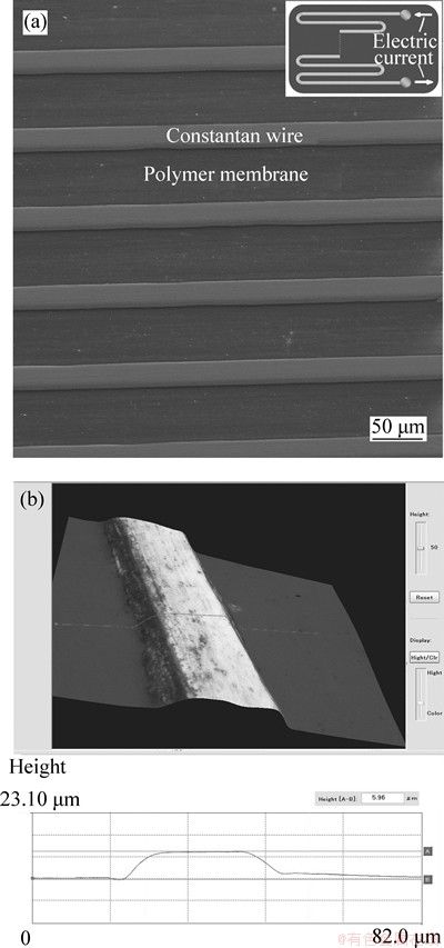
Fig. 1 SEM image of constantan-wire/polymer structure (a), and 3D super-depth digital microscope image for determining height of constantan wire (b)
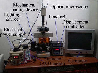
Fig. 2 Experimental setup for combined electrical and mechanical loading, where electrical loading was applied to constantan wire and mechanical loading was imposed on sample supporter
3 Results and discussion
3.1 Buckling-driven delamination
After the coupled electrical-mechanical loading, the parallel segments of the constantan wire were observed to buckle from the polymer membrane. Figures 3(a), (b) and (c) display three typical buckling morphologies of three constantan wires under electrical-tensile and electrical-compressive loadings. The arrows indicate the directions of the applied mechanical loading. The buckling morphologies are similar to the reported buckling-driven delamination only under electrical loading [15,17].
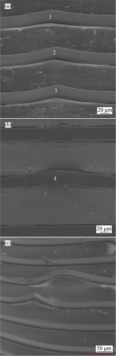
Fig. 3 Buckling morphologies of constantan wire on polymer membrane after combined action of 2.8×10⁸ A/m2 AC and 0.012 tensile strain (a), 0.076 compressive strain (b) and 0.168 compressive strain (c)
The buckling of the constantan wire was triggered by the relative thermal mismatch between the constantan wire and the polymer substrate, due to the different thermal expansion coefficients (TECs) of the constantan wire (αc=14.9×10⁻⁶ K-1) and the polymer membrane (αp=70×10-6 K-1). The applied mechanical loading gives the same strain to the polymer membrane and the constantan wire, whereas the electrical loading induces different stresses in the constantan wire and the polymer membrane. During the electrification process, the temperature of the sample increases quickly and then almost remains unchanged. When the electrical loading is ceased, the temperature gradually decreases and the polymer membrane shrinks faster due to the greater TEC, which results in biaxial compressive stress on the constantan wire. When the compressive stress exceeds the bonding strength between the constantan wire and the polymer membrane, the constantan wire will delaminate from the polymer membrane. The constantan wire tends to buckle in a curve shape like a compressed beam to minimize the potential energy. The mechanical loading may affect the buckling deflection and the buckling wavelength. However, it has little influence on the buckling morphologies of the constantan wire on the occasions of Figs. 3(a) and (b) compared with the reported buckling morphologies only under electrical loading [15, 17]. If the applied strain is large enough as the big compressive strain in Fig. 3(c), the polymer membrane will be distorted or even broken and the buckling shape of the constantan wire will not be sinusoid.
From the buckling morphologies of the constantan wires in Figs. 3(a) and (b), the interfacial toughness of the sample was estimated to evaluate the interfacial bonding capacity between the constantan wire and the polymer membrane. The interfacial toughness between the rigid constantan film wire and the flexible polymer membrane can be obtained from the following expression [13, 17]:
 (1)
(1)
where Δγ is the interfacial toughness,  means the bending rigidity of the constantan wire, λ represents the buckling wavelength, which is also called the delamination length, and w0 is the maximum buckling deflection of the constantan wire. This equation can be applied only under the situation that the film is incompressible compared with the substrate. In this study, Echc of the constantan wire is more than 5 times greater than Ephp of the polymer substrate. As a consequence, this equation can be approximately used to estimate the interfacial toughness of the constantan-wire/polymer structure.
Figure 4 shows the calculated interfacial toughnesses of the buckled constantan segments labeled in Figs. 3(a) and (b). The interfacial toughnesses between the constantan wire and the polymer membrane are greater than the reported values in Ref. [17]. The possible reason lies in the great diversity of the constantan-wire/polymer samples. It should be noted that the interfacial toughness cannot be calculated from Fig. 3(c), because the shape of the buckled constantan segments are not sinusoid owing to the big compressive strain exerted on the sample.

Fig. 4 Interfacial toughness of buckled constantan segments labeled in Fig. 3(a) and (b)
3.2 Fracture and folding based on buckling
Besides buckling-driven delamination, several other instability modes along with bucking were also observed under the coupled electrical-mechanical loading. Figure 5 illustrates the instability modes based on buckling of the constantan wire on the polymer membrane after the coupled electrical-tensile loading. In Fig. 5(a), the buckled constantan wire suffers a fracture around the top of the buckling under AC 2.8×10⁸ A/m2 and tensile strain 0.009. The fracture is caused by the combined effect of the applied mechanical tensile stress and the buckling bending stress of the constantan wire. On the other hand, when the applied mechanical tensile strain is large, such as under AC 2.8×10⁸ A/m2 and tensile strain 0.021 in Fig. 4(b), the polymer membrane tends to fracture besides the bucking of the constantan wire as a result of the mechanical compressive stress and the compressive stress generated from the TEC difference during the electrical loading process.
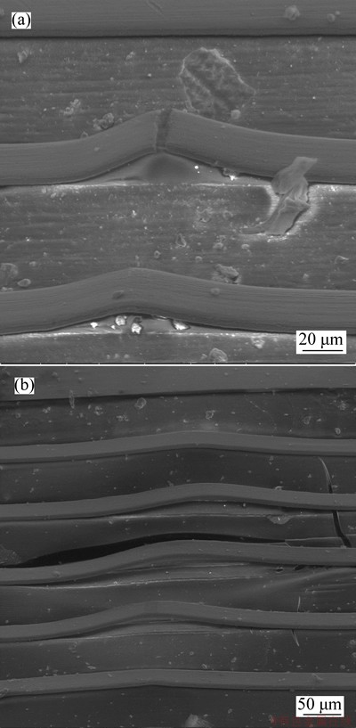
Fig. 5 Instability modes based on buckling of constantan wire on polymer membrane after combined effect of AC 2.8×10⁸ A/m2 and tensile strain of 0.009 (a) and 0.021 (b)
Figure 6 displays the instability modes of the
sample under the coupled electric-compressive loading. The buckling direction of the constantan wire, depending on the disturbance acted on the sample, may point to the inside of the polymer membrane as shown in Fig. 6(a) with compressive strain 0.066. The fracture of the constantan wire results from the bending tensile stress of the buckling. More generally, the buckled constantan wire is likely to be folded at the top of the buckling region, i.e., the folding of the buckled wire, presented in Fig. 6(b) with compressive strain 0.083. The folding results from the fact that the buckled constantan wire is further extruded by the mechanical compressive stress. Moreover, when the applied mechanical compressive strain is large, the polymer membrane will buckle from the supporter and fracture under the buckled bending stress of the polymer membrane along with the folding of the buckled constantan wire, see Fig. 6(c) with compressive strain 0.102. All of the above instability modes are tended to realize energy minimization of the samples.
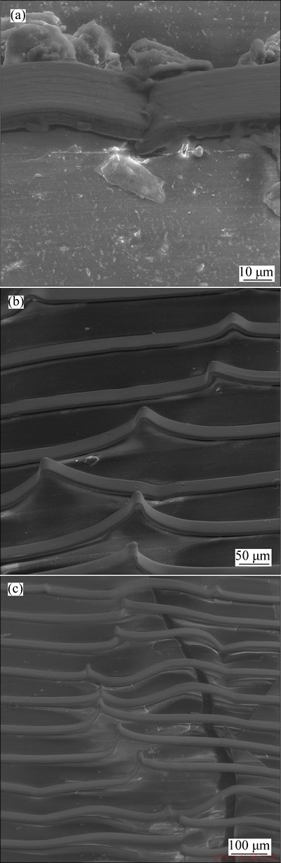
Fig. 6 Instability modes based on buckling of constantan wire on polymer membrane after combined effect of AC 2.8×10⁸ A/m2 and compressive strain of 0.066 (a), 0.083 (b) and 0.102 (c)
4 Conclusions
1) The buckling driven delamination of the constantan wire from the polymer membrane can emerge under both electrical-tensile and electrical-compressive loadings. When the applied mechanical loading is slightly greater, the polymer membrane tends to fracture along with the buckling of the constantan wire.
2) The fracture of the buckled constantan wire will appear under electrical-tensile loading. There are also several interesting instability modes under electrical- compressive loading, including the buckling towards the inside of the polymer membrane and the folding of the buckled constantan wire.
3) The instability mechanisms are analyzed and the interfacial toughness is estimated from the buckling morphology.
4) Although the research results about the buckling-related instability behaviors of metal-wire/ polymer structures under the coupled electrical- mechanical loading are preliminary, this work is promised to provide potential guidance in structure design, interface optimization and reliability evaluation of micro film-wire/flexible-substrate structures.
Acknowledgement
The author Qing-hua WANG acknowledges the financial support from the JSPS Postdoctoral Fellowship for Foreign Researchers.
References
[1] KHANG D Y, JIANG H Q, HUANG Y, ROGERS J A. A stretchable form of single-crystal silicon for high-performance electronics on rubber substrates [J]. Science, 2006, 311(5758): 208-212.
[2] KIM S, WON S, SIM G D, PARK I, LEE S B. Tensile characteristics of metal nanoparticle films on flexible polymer substrates for printed electronics applications [J]. Nanotechnology, 2013, 24(8): 085701.
[3] CORDILL M J, SCHMIDEGG K, DEHM G. Interface failure and adhesion measured by focused ion beam cutting of metal-polymer interfaces [J]. Philosophical Magazine Letters, 2011, 91(8): 530-536.
[4] JIANG H Q, SUN YG, ROGERS J A, HUANG Y. Mechanics of precisely controlled thin film buckling on elastomeric substrate [J]. Applied Physics Letters, 2007, 90(13): 133119.
[5] ABDALLAH A A, KOZODAEV D, BOUTEN P C P, den TOONDER J M J, SCHUBERT U S, de WITH G. Buckle morphology of compressed inorganic thin layers on a polymer substrate [J]. Thin Solid Films, 2006, 503(1/2): 167-176.
[6] YIN J, CHEN X. Buckling patterns of thin films on compliant substrates: The effect of plasticity [J]. Journal of Physics D: Applied Physics, 2011, 44(4): 045401.
[7] WU D, XIE H M, YIN Y J, TANG M J. Micro-scale delaminating and buckling of thin film on soft substrate [J]. Journal of Micromechanics and Microengineering, 2013, 23(9): 035040.
[8] YUN Y H, JANG S A, OH Y J. Formation of stretchable metal bi-layer interconnects using a deformed elastomeric polymer substrate [J]. Korean Journal of Metals and Materials, 2013, 51(2): 151-158.
[9] SUN Y G, CHOI W M, JIANG H Q, HUANG Y, ROGERS J A. Controlled buckling of semiconductor nanoribbons for stretchable electronics [J]. Nature Nanotechnology, 2006, 1: 201-207.
[10] GEORGE M, COUPEAU C, COLIN J, GRILHE J. Mechanical behaviour of metallic thin films on polymeric substrates and the effect of ion beam assistance on crack propagation [J]. Acta Materialia, 2005, 53(2): 411-417.
[11] HEINRICH M, GRUBER P, ORSO S, HANDGE U A, SPOLENAK R. Dimensional control of brittle nanoplatelets. A statistical analysis of a thin film cracking approach [J]. Nano Letters, 2006, 6(9): 2026-2030.
[12] FRANK S, HANDGE U A, OLLIGES S, SPOLENAKA R. The relationship between thin film fragmentation and buckle formation: Synchrotron-based in situ studies and two-dimensional stress analysis [J]. Acta Materialia, 2009, 57(5): 1442-1453.
[13] VELLA D, BICO J, BOUDAOUD A, ROMANA B, REISC P M. The macroscopic delamination of thin films from elastic substrates [J]. Proceedings of the National Academy of Sciences, 2009, 106(27): 10901.
[14] BOWDEN N, BRITTAIN S, EVANS A G, HUTCHINSON J W, WHITESIDES G M. Spontaneous formation of ordered structures in thin films of metals supported on an elastomeric polymer [J]. Nature, 1998, 393: 146-149.
[15] WANG Q H, XIE H M, FENG X, CHEN Z J, DAI F L. Delamination and electromigration of film lines on polymer substrate under electrical loading [J]. IEEE Electro Device Letters, 2009, 30(1): 11-13.
[16] WANG Q H, YIN Y J, XIE H M, LIU J, CHEN P W, ZHANG Q M. Buckling modes of polymer membrane restricted by metal wires [J]. Soft Matter, 2011, 7: 2888-2894.
[17] WANG Q H, XIE H M, LU J, CHEN P W, ZHANG Q M. Measurement of interfacial toughness of metal film wire and polymer membrane through electricity induced buckling method [J]. Journal of Colloid and Interface Science, 2011, 358(2): 491-496.
[18] WU D, XIE H M, WANG Q H. An investigation on the interfacial toughness of the metal thin film/polymer substrate [C]//Proceedings of the ISEM-ACEM-SEM-7th ISEM'12-Taipei Conference. Taipei, 2012.
[19] KIM D, HWANG H S, KHANG D Y. Electromechanical stability of buckled thin metal films on elastomer [J]. Thin Solid Films, 2011, 519(16): 5511-5515.
聚合物膜上的微尺度金属导线在力电耦合作用下的屈曲行为
王庆华1, 2, 岸本哲1, 谢惠民2, 李艳杰3, 吴丹2
1. 日本国立物质材料研究所 复合材料部门,筑波 305-0047;
2. 清华大学 航天航空学院 应用力学教育部重点实验室,北京 100084;
3. 济南大学 土木建筑学院,济南 250022
摘 要:研究一种典型的微尺度康铜线/聚合物膜结构在力电耦合作用下的屈曲行为。根据卸载后康铜线从聚合物基底上屈曲的现象,评估康铜线与聚合物基底间的界面韧性。此外,力电耦合作用还会诱发新的失稳模态。在电载荷和拉伸载荷作用下,康铜线易在屈曲时发生断裂。在电载荷和压缩载荷作用下,康铜线易在屈曲区域的顶部发生折叠,偶尔还会向聚合物基底内部方向发生屈曲。分析了这些失稳模态的产生机理。
关键词:屈曲分层;失稳模态;电载荷;机械载荷;界面韧性
(Edited by Can-hua CHEN)
Foundation item: Projects (2010CB631005, 2011CB606105) support by the National Basic Research Program of China; Projects (11232008, 91216301, 11227801, 11172151) supported by the National Natural Science Foundation of China; Project supported by Tsinghua University Initiative Scientific Research Program
Corresponding author: Hui-min XIE; Tel: +86-10-62792286; Fax: +86-10-62781824; E-mail: xiehm@mail.tsinghua.edu.cn
DOI: 10.1016/S1003-6326(14)63389-6

