
Protection behavior of fluorine-containing cover gases on molten magnesium alloys
XIONG Shou-mei(熊守美), WANG Xian-fei(王先飞)
State Key Laboratory of Automotive Safety and Energy,
Department of Mechanical Engineering, Tsinghua University, Beijing 100084, China
Received 1 September 2009; accepted 15 December 2009
Abstract: The sulphur hexa-fluoride gas(SF6), which is commonly used as the cover gas of molten magnesium alloys in the magnesium industry today, has an extremely high global warming potential(GWP). The protection mechanism of SF6 containing cover gases on molten magnesium alloys was presented. The cover gas protects the melt by reacting with the melt to form a coherent protective film on the melt surface. The film contains MgO and MgF2. Particles containing MgF2 form on the interface between the oxide film and the bulk magnesium alloy, which correspond to the concave areas from the surface observation. These particles increase the Pilling and Bedworth ratio of surface film and enhance the protective capability of the films. Based on the understanding of the mechanism of SF6, a melting technology in a sealed furnace was proposed, and the protection behavior of magnesium alloys in the sealed melting furnace was investigated under the protective atmosphere containing HFC-134a. The morphology and composition of the surface film were also studied. Experiments to evaluate the protective effect of two other fluorine containing gases with low GWPs on AZ91D alloy in the sealed furnace were also carried out, and the results show that the new gases are potential substitutes for SF6.
Key words: magnesium alloy; melt protection; SF6; surface film; protection mechanism
1 Introduction
Magnesium and its alloys are being widely used in many areas due to their excellent properties such as high specific strength and low density[1]. However, molten magnesium and its alloys oxidize rapidly in air, and magnesium oxide film does not protect the molten metal from further oxidation[2]. Protection with a cover gas mixture containing SF6 has been commonly used in magnesium industry in the past decades, but the SF6 gas has recognized as a very potent greenhouse gas with a high global warming potential (GWP) value of 23 900 compared with CO2 and a long atmospheric lifetime of 3 200 years[3]. Therefore, the magnesium industry has been looking for new substitutes for SF6.
FRUEHLING and HANAWALT[4] firstly studied the protection effect of molten magnesium under protective atmosphere of SF6 containing cover gases, and found that SF6 was consumed in the protection process and proposed that the absorption of SF6 to the MgO surface prevented the melt from further oxidation. CASHION[5] reported that the surface film formed in protective atmosphere containing SF6 was a mixture of MgO and MgF2 phases and the film thickness varied between 1 μm and 2 μm. PETTERSEN et al[6] analyzed the microstructure characteristic of the surface film formed in F-containing cover gas with XRD, EPMA and TEM, and found that long-term exposure of magnesium melt to the mixture gases containing SF6 increased the film thickness with an increasing concentration of MgF2. AARSTAD[7] indicated that particles containing MgF2 formed at the interface between MgO film and bulk magnesium, and the particles would grow up until they covered 25%-50% of the total film.
In 1998, the International Magnesium Association had committed to find suitable substitutes for SF6, and three of them were determined to be the most possible substitutes. HFC-134a was developed by the Cooperative Research Center for Cast Metals Manufacturing in Australia[8]. GWP value of HFC-134a is 18 times lower than that of SF6 and its atmospheric lifetime is only 14.6 years. HFE7100 and Novec 612TM were developed by 3M[9]. The GWP value and lifetime of HFE7100 are 75 times and 780 times lower than those of SF6. Novec 612TM has the same GWP value as CO2 and its lifetime is less than a week. However, these substitutes have not been widely used in magnesium industry.
The protection mechanism of SF6 containing cover gases on molten magnesium has not been clearly understood and needs further studies. In this work, the protection mechanism is discussed and a vacuum assisted melting technology is presented. The potential substitutes for SF6 are also presented.
2 Protection mechanism of SF6 containing cover gases
2.1 Experimental methods
AM60 and AZ91D alloys were used in the study and the alloys were melted in an electric resistance furnace under a mixture of SF6 and a diluent gas of N2 or CO2 that were controlled by mass flow meters. When a constant melt temperature was reached in the furnace, the original oxide film on the melt was removed to obtain a fresh melt surface, and then the melt was kept in the furnace for a period time. The crucible was then pulled out of the furnace and cooled rapidly using the compressed gases. Specimens for X-ray diffractometry, scanning electron microscopy analyses were cut from the samples. Specimens for cross-section observation of the film were coated with epoxy resin before grinding and polishing.
2.2 Experimental results and discussion
2.2.1 Film appearance and structure
Fig.1 shows the cross-section view of the sample with 0.3% (volume fraction, the same below if not mentioned) SF6 held at 680 ?C for 10 min. It can be seen from Fig.1 that the surface film is dense and uniform in thickness with some semicircular particles formed at the interface between the oxide film and bulk magnesium, and these particles combine closely with the protective film and are embedded into bulk magnesium alloy. Fig.2 shows the surface morphology of a sample in 0.1% SF6 held at 680 ?C for 10 min. It can be seen from Fig.2 that there are many concavities on the surface film inside which the grain size is smaller compared with that of the other flat areas.
2.2.2 Composition of surface film
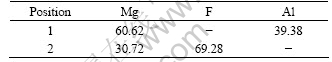
The EDS results listed in Table 1 and Table 2 indicated that the concavities in Fig.2 are mainly composed of magnesium and fluorine elements with a small amount of oxygen, which is in accordance with the composition of those particles on the interface view. It can be concluded that these particles from the interface
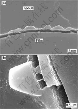
Fig.1 SEM images of cross-section sample with 0.3% SF6 held at 680 ?C for 10 min (a) and particles between bulk magnesium alloy and MgO film (b)
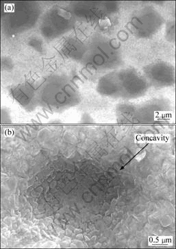
Fig.2 SEM images of surface morphology of sample in 0.1% SF6 held at 680 ?C for 10 min (a) and concavity with finer grains (b)
view are MgF2 corresponded to the concavities(dark areas) from surface observation as shown in Fig.3. However, the EDS results also show that the compositions of other areas (bright areas) from surface observation are Mg, O and F with large concentration of oxygen element, and all XRD patterns of the samples contain the peaks of MgF2 and MgO compounds, which indicates that these films are composed of MgF2 and MgO phases with some particles contained MgF2 form at the interface between the oxide film and the bulk magnesium.

Fig.3 EDS analyses for concavities and particles as well as flat areas on surface
Table 1 Particle composition (mole fraction, %)
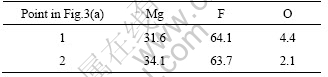
Table 2 Film composition (mole fraction, %)

2.2.3 Film appearance at different exposure time
Fig.4 shows the surface morphology of samples in 0.1% SF6 held at 680 ?C for different exposure time. It can be seen from Fig.4 that the surface morphology changes greatly with the increase of the holding time. At 3 min, the surface film contains mainly MgO with a small concentration of MgF2. As the holding time increases to 30 min, the number of particles containing MgF2 in the film increases greatly and keeps almost unchanged even as the holding time increases to 60 min.
It is known that magnesium oxide film does not protect the molten magnesium from further oxidation due to the mismatch of the mole volume of magnesium oxide and the mole volume of the equivalent amount of magnesium(the Pilling-Bedworth ratio)[10-11]. Since the Pilling-Bedworth ratio of the magnesium oxide film is 0.73[12], magnesium ion can still react with oxygen on the surface of samples by diffusing through the porous oxide film. When some particles containing MgF2 with a Pilling-Bedworth ratio of 1.29[12] formed in the film, the film becomes dense and can protect the melt effectively.
In the early stage of the experiment, the film only containing MgO forms on the surface of samples by the prior reaction between magnesium and oxygen in the atmosphere. However, since MgF2 is a more stable phase than MgO in the system from thermodynamic point of view[13], magnesium ion can continually react with fluorine to form MgF2 and the concentration of MgF2 in the film increases with the increase of the holding time. The fluorine atoms can also diffuse through the surface film to the interface between the oxide film and bulk magnesium to form MgF2 particles until the diffusion is stopped by the particles. Meanwhile, the diffusion of magnesium ion to the film surface is also prevented.
3 Vacuum assisted melting technology for magnesium alloys in sealed furnace
3.1 Introduction
Magnesium and magnesium alloys are usually protected under an open condition with the cover gases continually flowed through the melting furnace. It wastes a large quantity of cover gases and has a bad impact on the atmosphere and the operator. Based on the understanding of the protection mechanism of the cover gases containing SF6, a vacuum assisted melting technology for magnesium alloys in a sealed furnace was proposed to directly form a layer of MgF2 during the melting process.
3.2 Experimental method
Fig.5 shows a schematic diagram of the melting furnace. Pressure in the furnace can be pumped to below 6 Pa and the pressure rising rate is below 0.67 Pa/h.
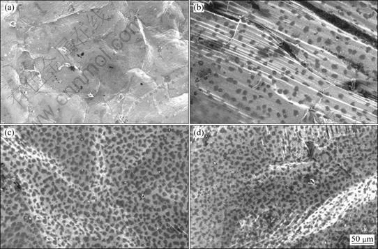
Fig.4 SEM images of surface morphology of samples in 0.1% SF6 held at 680 ?C for different exposure time: (a) 3 min; (b) 10 min; (c) 30 min; (d) 60 min

Fig.5 Schematic diagram of melting furnace
Firstly, the pressure in the furnace was pumped to a vacuum level of 6 Pa, and then, the gas mixture of HFC-134a or SF6 and N2 controlled by flow meters was filled into the furnace. Finally, the gas inlet valve and the flow meter were closed when the pressure in the furnace was increased to 105 Pa. When the protective effect of gas mixture of HFC-134a, N2 and air was considered, the gas mixture of HFC-134a and N2 would be filled into the furnace first to a certain pressure level, and then the air was filled until the pressure in the furnace was increased to 105 Pa. The protection effect on molten magnesium alloys and the impact of adding air into the atmosphere on the surface morphology and composition in the film were studied.
3.3 Experimental results and discussion
3.3.1 Protective effects
Table 3 lists the protection effects on molten magnesium alloy at different melting temperatures and cover gases contents. It can be seem from Table 3 that, all the protective atmospheres containing different cover gases can perform excellent protection on molten magnesium alloy at 760 ?C, and the minimum concentration of HFC-134a in the protective atmosphere for protection on the molten magnesium is 0.003%.
Table 3 Protective effect of melting temperature and cover gases content on molten magnesium alloy
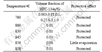
Protective effect is reduced by the increase of melting temperature when the concentration of cover gases is fixed at a constant value, and when the concentration of cover gases is increased, the effective protective temperature on melt is increased with the highest protective temperature up to 856 ?C.
3.3.2 Film appearance and structure
Fig.6 shows the surface morphologies of samples with 0.01% HFC-134a and different air pressures held at 760 ?C for 2 h. It can be seen from Fig.6 that the roughness of the surface film is increased with the increase of air concentration in the cover gases, and finally the surface film presents irregular net structure under atmosphere with 80% air.

Fig.6 SEM images of surface morphology of samples with 0.01% HFC-134a under different air pressures at 760 ?C for 2 h: (a) 2.3 kPa; (b) 8 kPa; (c) 80 kPa
3.3.3 Composition of surface film
Table 4 lists the EDS results of the surface film in Fig.6. The oxygen concentration in the film increased with the reduction of the carbon content when the air concentration in the gas mixture was increased, as more reactions happened between magnesium and oxygen, and the carbon in the film further reacted with oxygen to form CO and CO2, which went into the atmosphere. Fig.7 shows the cross-section view and element backscattered electron image of a sample in 0.3% SF6 and N2 held at 690 ?C for 2 h in the sealed furnace. Table 5 lists the EDS results of the surface film. It can be seen from Table 5 that a surface film of pure MgF2 is formed on the surface of magnesium alloy, having excellent protection performance on molten magnesium alloy.
Table 4 EDS results of surface films in Fig.6 (mole fraction, %)
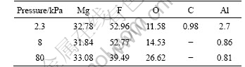
Table 5 EDS results of surface films in Fig.7 (mole fraction, %)
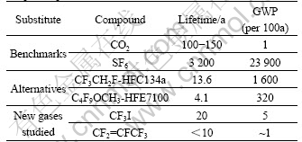
4 Studies on substitutes for SF6
Table 6 lists the global warming potential values of SF6 and potential substitutes for SF6. It can be seen from Table 6 that HF-134a and HFE7100 gases still have a high GWP value and can only be used as the transitional substitutes for SF6. The magnesium industry is urgent to find new substitutes for SF6 with low GWP value and short atmospheric lifetime. As shown in Table 6, two kinds of F containing gases have a low GWP values and relatively short atmospheric lifetime. Their protecting effects on molten magnesium alloys were studied and the results showed that the cover gas mixture containing either of the two gases could perform a well protection on molten magnesium alloy from further oxidation in the sealed furnace, which shows that these two gases could be potentially used as substitutes for SF6 in magnesium industry.
On the other hand, before SF6 was widely used in magnesium industry, SO2 was commonly used as the protective cover gas, but the protective mechanism of SO2 on molten magnesium alloy has not yet been clearly understood. Therefore, studies on protective mechanism of SO2 on molten magnesium alloy will provide positive theoretical basis for finding new substitutes for SF6.
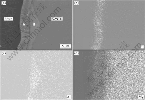
Fig.7 Mapping results of surface film: (a) SEM image of cross section; (b) Mapping result of fluoride; (c) Mapping result of aluminium; (d) Mapping result of magnesium
Table 6 GWP value of SF6 and potential substitutes for SF6[14-16]
5 Conclusions
1) Compact and coherent surface film containing MgO and MgF2 forms on the molten magnesium alloy in the protective atmosphere containing SF6. The protective film is composed of MgO, and with the increase of the holding time, particles containing MgF2 forms on the interface between the oxide film and bulk magnesium by fluorine ion diffusing through the porous magnesium oxide film and reacting with magnesium ion, which makes the oxide film protective.
2) A vacuum assisted melting technique in a sealed furnace to directly form a layer of MgF2 was presented. HFC134a/N2 atmosphere is suitable for protecting AZ91D magnesium alloy in the sealed furnace. The minimum concentration to protect magnesium melt at 760 ?C is 0.003% and no continuous inlet of the cover gas mixture is needed in the sealed furnace.
3) CF3I and C3F6 have low GWP value and short atmospheric lifetime, and could also perform excellent protection on magnesium and magnesium alloy in the sealed furnace, which shows that they are potential substitutes for SF6 in magnesium industry. The protection mechanism of SO2 on magnesium melt needs further study for other substitutes of SF6.
References
[1] THARUMARAJAH A, KOLTUN P. Is there an environmental advantage of using magnesium components for light-weighting cars [J]. Journal of Cleaner Production, 2007, 15: 1007-1013.
[2] MEBARKI N, RAVI KUMAR N V, BLANDIN J J, SUERY M, PELLOUX F, KHELIFATI G. Correlation between ignition and oxidation behaviors of AZ91 magnesium alloy [J]. Materials Science and Technology, 2005, 21(10): 1145-1151.
[3] ZENG Yi-wen, MAO Ming-xian, HUANG Zhi-qiang. Research on magnesium melting protected by cover gas mixtures containing HFC-32 [J]. Foundry, 2006, 55(8): 776-779. (in Chinese)
[4] FRUEHLING J W, HANAWALT J D. Protective atmospheres for melting magnesium alloys [J]. American Foundryman’s Society Transactions, 1969, 77: 159-164.
[5] CASHION S P. The use of sulphur hexafluoride(SF6) for protecting molten magnesium [D]. Australia: Department of Mining, Minerals and Materials Engineering, University of Queensland, 1998.
[6] PETTERSEN G, ?VRELID E, TRANELL G. Characterization of the surface films formed on molten magnesium in different protective atmospheres [J]. Materials Science and Engineering A, 2002, 332: 285-294.
[7] AARSTAD K. Various techniques to study the surface of magnesium protected by SF6 [C]//Magnesium Technology 2003. San Diego, USA: TMS, 2003: 35-38.
[8] BAKER P W, FROST M T. Cover gases. Australia, WO0064614[P], 2000.
[9] DEAN S M. Development of 3MTM NovecTM 612 magnesium protection fluid as a substitute for SF6 over molten magnesium [C]//International Conference on SF6 and the Environment. San Diego, USA: US EPA (United States Environmental Protection Agency), 2002.
[10] PILLING N B, BEDWORTH R E. The oxidation of metals at high temperature[J]. Journal of the Institute of Metals, 1923(29): 29-33.
[11] ZHOU Hong, WANG Ming-xing, LI Wei, WANG Lin, ZHAO Yu. Effect of Ce addition on ignition point of AM50 alloy powders [J]. Materials Letters, 2006, 60: 3238-3240.
[12] WON H, YOUNG J K. Effects of cover gases on melt protection of Mg alloys [J]. Journal of Alloys and Compounds, 2006, 422: 208-213.
[13] TENG S S, JYUN B L, PAI S W. Oxide films on magnesium and magnesium alloys [J]. Materials Chemistry and Physics, 2007, 104: 497-504.
[14] HILLIS J E. The international program to identify alternatives to SF6 for magnesium melt protection [C]//International Conference on SF6 and the Environment. San Diego, USA: US EPA (United States Environmental Protection Agency), 2002.
[15] JAMES M C. The next generation of refrigerants-historical review, considerations, and outlook [J]. International Journal of Refrigeration, 2008, 31: 1123-1133.
[16] BARTOS S, CURTIS L, SCHARFENBERG J, KANTAMANENI R. Reducing greenhouse gas emissions from magnesium die casting [J]. Journal of Cleaner Production, 2007, 15: 979-987.
(Edited by LI Xiang-qun)
Foundation item: Project(2009AA03Z114) supported by the National High-Tech Research and Development Program of China; Project supported by Tsinghua-Toyo R&D Center of Magnesium and Aluminum Alloys Processing Technology, China
Corresponding author: XIONG Shou-mei; Tel: +86-10-62773793; Fax: +86-10-62773793; E-mail:smxiong@tsinghua.edu.cn
DOI: 10.1016/S1003-6326(09)60283-1

