水泥路面板底脱空注浆布孔方案设计及注浆压力计算方法
赵健1, 2,邹金锋1,曾胜1, 2,罗恒1
(1. 中南大学 土木建筑学院,湖南 长沙,410075;
2. 长沙理工大学 交通科学研究院,湖南 长沙,410076)
摘 要:为了从理论上分析水泥混凝土路面板底脱空注浆加固的压力控制及布孔方式,以劈裂注浆压力及扩散半径的理论公式为基础,假设浆液在土体裂缝中的流动符合达西定律,劈裂注浆形成的裂缝宽度为均匀裂缝宽度,推导出水泥混凝土路面板脱空注浆时两孔、三孔、四孔和五孔注浆布置方案在注浆加固的布孔方式下注浆压力设计计算方法。研究结果表明:理论计算结果与实测结果较接近,证明了计算方法的合理性,理论分析的结果可为工程应用提供可靠依据。
关键词:路面板;脱空注浆;布孔方式;注浆压力
中图分类号:TU443 文献标志码:A 文章编号:1672-7207(2010)06-2344-06
Design of holes arrangement and grouting pressure for void road panel
ZHAO Jian1, 2, ZOU Jin-feng1, ZENG Sheng1, 2, LUO Heng1
(1. School of Civil and Architectural Engineering, Central South University, Changsha 410075, China;
2. Institute of Traffic Science, Changsha University of Science & Technology, Changsha 410076, China)
Abstract: In order to analyze the design of holes arrangement and its grouting pressure of void treatment beneath cement concrete pavement, based on the assumption that the grouting flow in soil crack is in accordance with H.Darcy law and the last formative crack breadth is even crack breadth, 2, 3, 4 and 5 designs of holes arrangement and grouting pressure for void road were given. These conclusions are proved true by making use of numerical analyses method. These theories are useful for engineering application.
Key words: road panel; void grouting; design of holes arrangement; grouting pressure
近年来,我国高速公路的建设速度很快,通车里程非常大。其中大部分路面的质量良好,但也有不少路段在建成通车后不久,短的几个月,长的2~3 a,就不得不进行大面积维修,路面的早期损坏问题引起了人们的广泛关注[1-9]。到目前为止,人们对高等级公路路面、路基等病害的处理方法并不多,多数是沿用低等级公路的养护经验、设备、方法,不能满足高等级公路要求。采用灌浆处治快速施工是处治路面板病害的有效方法之一[10-14]。但是,目前人们对灌浆处治路基沉降病害的机理尚不清晰,注浆压力设计计算方法、浆液扩散范围、有效加固范围、注浆终止条件、注浆工艺、注浆处治效果的检测与评估等都处于经验阶段。因此,深入开展路面板病害的注浆处治快速施工关键技术研究,具有重要的工程应用价值和理论价值。在此,本文作者从路面板注浆加固的机理出发,研究路面板脱空注浆加固的布孔方式、注浆压力设计计算等理论问题,以期为路面板脱空注浆加固的设计计算及施工等维护提供理论依据。
1 注浆压力及扩散半径
根据文献[15],距注浆孔距离为r处的注浆压力为:
 (1)
(1)
式中:pr为半径r处的注浆压力;pc为注浆孔内压力;μ为运动黏度; 为初始裂缝宽度;Q为注浆量;rc为注浆孔的半径。式(1)表明:在注浆过程中,距离注浆孔轴线为r的任意一点处的注浆压力衰减与扩散半径的对数、注浆量、浆液黏度系数和注浆压力成正比,与裂缝宽度的3次方成反比。因此,裂缝的宽度愈小,压力衰减得愈快。
假设土体的劈裂注浆压力为p0,则当注浆压力pr=p0时,可求得在注浆压力pc作用下的最大扩散半径Rmax:
 (2)
(2)
从式(2)可以看出:最大扩散半径与裂缝的3次方的指数成正比,与黏滞系数倒数的指数成正比,与注浆孔半径成正比。
当浆液扩散半径达到最大值时,可以求得单一裂缝的注浆量 为:
为:
 (3)
(3)
从式(3)可以看出:单一裂缝的注浆量与裂缝宽度的3次方成正比,与黏滞系数成反比。因此,利用式(2)和(3)可以求得一定注浆压力下的最大扩散半径和单一裂缝的注浆量。
2 多孔注浆时布孔方案分析
2.1 矩形方案布孔
相邻注浆孔的相互交圈示意图见图1。下面讨论图1中按照矩形顶点布置4个注浆孔注浆时的相互影响问题。
设4个注浆孔的注浆压力均相等,对于外部边界条件无任何限制,注浆孔中的浆液源为线性源。由式(4)并利用注浆压力在土体中的叠加原理可知:某点M的注浆压力 为:
为:
 (4)
(4)

图1 相邻注浆孔的相互交圈示意图
Fig.1 Intercross schematic diagram of adjacent grouting hole
当r1=r2=r3=r4时,可由式(4)获得注浆压力最小值。此时,矩形布孔正好呈正方形,则最小值点的注浆压力为:
 (5)
(5)
注浆时,若实现各注浆孔的影响半径正好相接,则此半径即为矩形布孔注浆时浆液扩散半径的最优值。此时,单孔注浆的浆液扩散半径为:
 (6)
(6)
式中:Rr为注浆半径设计值;a和b分别为矩形的长度和宽度。对于面积为4 m×5 m的矩形路面板,若注浆的扩散半径为1 m,则只需布置4个注浆孔即可。具体布置方法如图2所示。
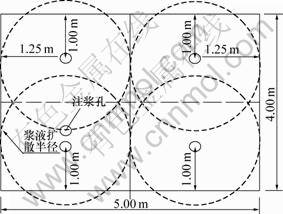
图2 孔注浆时的布置方案图
Fig.2 Layout scheme of grouting hole
由于现有规范规定路面板的抬升高度不能超过5 mm,因此,假定混凝土板在注浆加固后的整体抬升高度为规范规定值5 mm,则单孔注浆需要的注浆量为:Q=0.25×0.005×4×5=0.025 (m3);浆液裂缝宽度也为5 mm;浆液黏度μ=1.5×10⁴ kPa。同时,由于混凝土板已经脱空,因此,不存在劈裂混凝土板与土体之间的劈裂注浆压力,即p0=0。据此可求出注浆的孔口控制压力为175.905 kPa。
因此,若为四孔布置注浆方案,则需要的注浆压力为0.175 MPa,注浆扩散半径为1.25 m,单孔注浆量为0.025 m3,板体抬升高度不超过5 mm。
2.2 三角形布孔方案
按照三角形顶点布置3个注浆孔(如图3所示),注浆设计半径Rt最小时的注浆压力 求解如下。
求解如下。

图3 三角形布孔方案
Fig.3 Triangular layout scheme of three holes
根据注浆压力的叠加原理,R1点的注浆压力
 (7)
(7)
在矩形注浆区域内,求式(7)的最小值,得注浆压力最小值。根据求最值理论,当r1=r2=r3时,式(7)可以获得最小值,此时的布孔正好呈三角形。最小值点的注浆压力为:
 (8)
(8)
同理,注浆时若实现各注浆孔的影响半径正好相接,则此半径即为三角形布孔注浆时浆液扩散半径的最优值。
根据海伦公式:

以及正弦定律可求得三角形外接圆的半径Rt为:
 (9)
(9)
此即为单孔注浆的浆液扩散半径。其中:S为三角形的面积;s=(a+b+c)/2;Rt为注浆半径设计值;a,b和c为三角形的边长。
对于面积为4 m×5 m的矩形路面板,若注浆的扩散半径为1.25 m,则只需布置3个注浆孔即可。具体布置方法如图4所示。

图4 三孔注浆时的布置方案图
Fig.4 Layout scheme of three grouting holes
同样,假定混凝土板在注浆加固后的整体抬升为5 mm,则浆液裂缝宽度也为5 mm;浆液黏度μ=1.5×10⁴ kPa;同时,由于混凝土板已经脱空,因此,不存在劈裂混凝土板与土体之间的劈裂注浆压力,即p0=0 kPa。至于单孔注浆量,由于注浆孔1和注浆孔2的浆液扩散半径相同,因此,应该注入相同的注浆量;而对于注浆孔3,其浆液扩散半径是注浆孔1和注浆孔2的1.15倍,因此,其注浆量也应该是注浆孔1或注浆孔2的1.15倍。这样,注浆孔1和注浆孔2的注浆量为0.032 m3,注浆孔3的注浆量为0.036 m3。据此可知:注浆孔1和注浆孔2的孔口注浆控制压力为225.158 kPa,注浆孔3的扩孔注浆控制压力为261.086 kPa。
因此,若采用3孔布置注浆方案,则注浆孔1和注浆孔2需要的注浆压力为0.225 MPa,注浆扩散半径为1.25 m,单孔注浆量为0.032 m3;注浆孔3需要的注浆压力为0.26 MPa,注浆扩散半径为1.44 m,单孔注浆量为0.036 m3;板体抬升高度不超过5 mm。
为了验证三孔注浆布置方案的可靠性,取湖南省某高速公路路面板脱空注浆实验数据进行验证,注浆压力与时间的关系如图5所示。

图5 三孔注浆时的注浆压力与时间的关系
Fig.5 Relationship between grouting pressure and time of three grouting holes
从图5可以看出:注浆压力随着注浆时间的延长呈折线增大,并超出设计计算值,其原因是:实验中记录的是注浆机的孔口压力,而本文理论计算值则是浆液与路面板和土体接触的压力。因此,实验结果较理论计算结果偏大属于正常现象。此外,这也是注浆管的管阻造成的。在注浆过程中,注浆压力随注浆时间的增加不是单调增加,而呈波浪型上升,其主要是水泥混凝土板下材料与受力状况的不均匀性造成的。而本文是基于板底材料和其他状况均匀的条件下推导的,所以,理论值与实际值存在差异。在实际注浆过程中,当注浆压力达到设计压力并稳定3~5 min时,则可以停止注浆。
因为大多数路面板的破裂均呈现出如图6所示的破裂形式,所以,在路面板脱空补强中,应充分考虑采用三孔注浆布置方式。
2.3 两孔注浆布孔方案
2个孔注浆孔的相互交圈示意图如图7所示。下面讨论图7中按照矩形顶点布置2个注浆孔注浆时的相互影响问题。
设2个注浆孔的注浆压力相等,对于外部边界条件无任何限制,注浆孔中的浆液源为线性源。由式(6)并利用注浆压力在土体中的叠加原理可知:某点M的注浆压力 为:
为:
 (10)
(10)
在矩形注浆区域内,由式(10)求得的最小值即为注浆压力最小值。根据求最值理论,当r1=r2时,由式(10)可以获得最小值。此时,矩形布孔正好呈正方形,则最小值点的注浆压力为:
 (11)
(11)

图6 路面板破裂的常见形式
Fig.6 Common rupture form of pavement’s cement board

图7 2个孔注浆孔的相互交圈示意图
Fig.7 Intercross schematic diagram of two grouting holes
注浆时若实现各注浆孔的影响半径正好相接,则此半径即为矩形布孔注浆时浆液扩散半径的最优值。此时,单孔注浆的浆液扩散半径为:
(12)
对于面积为4 m×5 m的矩形路面板,若注浆的扩散半径为1.25 m,则只需布置2个注浆孔即可。具体布置方案见图8。

图8 两孔注浆时的布置方案图
Fig.8 Layout scheme of two grouting holes
假定混凝土板在注浆加固后的整体抬升高度为5 mm,则可知单孔注浆需要的注浆量为:Q=0.5×0.005×4×5=0.05 (m3);浆液裂缝宽度也为5 mm;浆液黏度μ=1.5×10⁴ kPa;同时,由于混凝土板已经脱空,因此,不存在劈裂混凝土板与土体之间的劈裂注浆压力,即p0=0 kPa。据此可求出注浆的孔口控制压力为351.809 kPa。
因此,若为两孔布置注浆方案,则需要的注浆压力为0.35 MPa,注浆扩散半径为1.25 m,单孔注浆量为0.05 m3,板体抬升高度不超过5 mm。
为了验证两孔注浆布置方案的可靠性,仍取湖南省某高速公路路面板脱空注浆实验数据进行验证,注浆压力与时间的关系如图9所示。

图9 两孔注浆时的注浆压力与时间的关系
Fig.9 Relationship between grouting pressure and time of two grouting holes
从图9可以看出:注浆压力随着时间的延长呈折线增大,实测值中除了管阻等外部阻力外,其余均与理论值较接近。
2.4 规范规定的路面板布孔方式
在现有规范中,路面板脱空注浆的布孔方式如图10所示(以路面板尺寸4 m×5m为例说明)。

图10 五孔注浆时的布置方案图
Fig.10 Layout scheme of five grouting holes
图10中,每块板均布置5个注浆孔,分别为注浆孔1、注浆孔2、注浆孔3、注浆孔4和注浆孔5。注浆孔半径均为1.25 m。注浆顺序为:注浆孔1→注浆孔3→注浆孔2→注浆孔4→注浆孔5。
采用本文理论,对现有规范规定的注浆孔布置方式进行注浆压力和注浆量设计。具体过程如下:由于假定混凝土板在注浆加固后的整体抬升高度为规范规定值5 mm,则可知单孔注浆需要的注浆量为:Q=0.2×0.005×4×5=0.020 (m3);浆液裂缝宽度为5 mm;浆液黏度μ=1.5×10⁴ kPa。同时,由于混凝土板已经脱空,因此,不存在劈裂混凝土板与土体之间的劈裂注浆压力,即p0=0 kPa。据此可求出注浆的孔口控制压力为140.724 kPa。
因此,若为五孔布置注浆方案,则需要的注浆压力为0.14 MPa,注浆扩散半径为1.25 m,单孔注浆量为0.02 m3,板体抬升高度不超过5 mm。
然而,在工程实践中,注浆的控制压力往往超过0.14 MPa,多采用0.5 MPa的注浆压力进行控制。其原因为:注浆孔1~4注浆之后,注浆孔5所需要注浆的区域有限,而且在轮到注浆孔5进行注浆时,路面板在注浆孔1~4的注浆作用下,浆液和路面板之间形成了较强劲的咬合力,使注浆孔5在最后的注浆中必须采用较大的注浆压力才能完成其应该填充的区域。从图10还可以看出:当注浆孔1~4注浆填充之后,其所剩区域处于路面板的中间部位,从板的受力特点可知,该区域应该是板受力最小的地方。因此,考虑到注浆施工过程中浆液充填的不可控制性,注浆孔5充填的区域或许早已在前4个注浆孔的注浆过程中被填满。因此,注浆孔5的注浆施工可以省略。
3 结论
(1) 获得了路面板脱空注浆过程中两孔、三孔、四孔和五孔注浆布置方案的理论设计计算方法。
(2) 获得了路面板脱空注浆加固的注浆压力设计计算方法。采用该设计计算方法所得结果与实际注浆状态下所得结果较吻合,具有一定的工程应用价值。
(3) 现有规范规定的五孔注浆布孔方案还存在一定的局限性,建议多采用三孔及两孔布置方案进行路面板的脱空注浆补强加固。
参考文献:
[1] 彭永恒, 张肖宁, 罗跃纲. 基于频率下降率的刚性路面脱空自适应神经网络识别研究[J]. 公路, 2004, 2(2): 50-53.
PENG Yong-heng, ZHANG Xiao-ning, LUO Yue-gang. Study on self-adaptive neural network identifying of void on rigid pavement based on frequency draw down ratio[J]. Highway, 2004, 2(2): 50-53.
[2] 张宁, 钱振东, 黄卫. 水泥混凝土路面板下地基脱空状况的评定与分析[J]. 公路交通科技, 2004, 21(1): 4-7.
ZHANG Ning, QIAN Zhen-dong, HUANG Wei. Void detection under PCC pavement[J]. Journal of Highway and Transportation Research and Development, 2004, 21(1): 4-7.
[3] 边加敏, 郝秀民. 农村水泥砼路面裂缝成因及预防研究综述[J]. 重庆交通学院学报, 2006(1): 35-37.
BIAN Jia-min, HAO Xiu-min. Outline of research in the reason of the rural cement concrete pavement fissure and the prevent [J]. Journal of Chongqing Jiaotong University, 2006(1): 35-37.
[4] 曾胜, 陈明宪. 水泥混凝土路面脱空与传荷作用机理研究[J]. 铁道科学与工程学报, 2005, 2(1): 68-72.
ZENG Sheng, CHEN Ming-xian. Research on the concrete pavement void and load transfer mechanism[J]. Journal of Railway Science and Engineering, 2005, 2(1): 68-72.
[5] 曾胜, 张显安. 水泥混凝土板下脱空状况时接缝处弯沉的影响分析[J]. 铁道科学与工程学报, 2005, 2(6): 31-36.
ZENG Sheng, ZHANG Xian-an. Analysis of deflection at joint on the condition of PCC void subgrade[J]. Journal of Railway Science and Engineering, 2005, 2(6): 31-36.
[6] 周玉民, 谈至明, 刘伯莹. 水泥混凝土路面脱空状态下的荷载应力[J]. 同济大学学报: 自然科学版, 2007, 35(2): 341-345.
ZHOU Yu-min, TAN Zhi-ming, LIU Bo-ying. Loading stresses in cement concrete pavement slab with void underneath[J]. Journal of Tongji University: Natural Science, 2007, 35(2): 341-345.
[7] 唐伯明. 刚性路面板底脱空状况的评定与分析[J]. 中国公路学报, 1992, 5(1): 40.
TANG Bo-ming. Evaluation and analysis for rigid pavements under void condition[J]. The Journal of China Highway, 1992, 5(1): 40.
[8] 曾胜, 王光明, 张起森. 基于FWD荷载分布系数直解路面结构层模量[J]. 公路交通科技, 2003, 20(4): 6-9.
ZENG Sheng, WANG Guang-ming, ZHANG Qi-sen. Calculating modulus of pavement structure course directly using FWD load distribution coefficient[J]. Journal of Highway and Transportation Research and Development, 2003, 20(4): 6-9.
[9] 曹东伟, 胡长顺. 水泥混凝土路面板底脱空判别方法研究[J]. 西安公路交通大学学报, 1998, 18(3): 4-8.
CAO Dong-wei, HU Chang-shun. Research on determining whether the cavity beneath cement concrete slabs occurred[J]. Journal of Xi’an Highway University, 1998, 18(3): 4-8.
[10] 吕惠卿, 张湘伟, 成思源. 水泥混凝土路面力学性能研究综述[J]. 重庆大学学报: 自然科学版, 2005, 28(6): 60-63.
L? Hui-qing, ZHANG Xiang-wei, CHENG Si-yuan. Study on mechanical properties of cement concrete pavements[J]. Journal of Chongqing University: Natural Science Edition, 2005, 28(6): 60-63.
[11] Huang Y H. Pavement analysis and design[M]. Englewood Cliffs: Prentice-Hall, 1993.
[12] American Association of State Highway and Transportation Officials. Guide for design of pavement structures[C]//American Association of State Highway and Transportation Officials. Washington DC, 1986.
[13] 陈钟祥, 刘慈群. 双重孔隙介质中二相驱替理论[J]. 力学学报, 1980, 12(2): 152-165.
CHEN Zhong-xiang, LIU Ci-qun. Theory of fluid displacement in a medium with double porosity[J]. Acta Mechanic Sinica, 1980, 12(2): 152-165.
[14] 孙斌堂, 凌贤长, 凌晨. 渗透注浆浆液扩散与注浆压力分布数值模拟[J]. 水力学报, 2007, 37(11): 1402-1407.
SUN Bin-tang, LING Xian-chang, LING Chen. Numerical simulation for diffusion and pressure distribution of permeation grouting[J]. Journal of Hydraulic Engineering, 2007, 37(11): 1402-1407.
[15] 邹金锋, 李亮, 杨小礼, 等. 劈裂注浆扩散半径及压力衰减分析[J]. 水利学报, 2006, 37(3): 314-319.
ZOU Jin-feng, LI Liang, YANG Xiao-li. Penetration radius and pressure attenuation law in fracturing grouting[J]. Journal of Hydraulic Engineering, 2006, 37(3): 314-319.
(编辑 陈灿华)
收稿日期:2010-03-10;修回日期:2010-05-25
基金项目:国家自然科学基金资助项目(50978037)
通信作者:赵健(1980-),男,湖南涟源人,博士研究生,从事地基与基础研究;电话:0731-82309329;E-mail: zhaojian711514@126.com

