Hybrid input shaping control scheme for reducing vibration of robot based on multi-mode control
��Դ�ڿ������ϴ�ѧѧ��(Ӣ�İ�)2019���6��
�������ߣ���� κ���� ŷ���� ������
����ҳ�룺1649 - 1660
Key words��hybrid control; input shaping; vibration suppression; multi-mode; robot
Abstract: The classic multi-mode input shapers (MMISs) are valid to decrease multi-mode residual vibration of manipulators or robots simultaneously. But these input shapers cannot suppress more residual vibration with a quick response time when the frequency bandwidth of each mode vibration is very different. The methodologies and various types of multi-mode classic and hybrid input shaping control schemes with positive impulses were introduced in this paper. Six types of two-mode hybrid input shapers with positive impulses of a 3 degree of freedom robot were established. The ability and robustness of these two-mode hybrid input shapers to suppress residual vibration were analyzed by vibration response curve and sensitivity curve via numerical simulation. The response time of the zero vibration-zero vibration and derivative (ZV-ZVD) input shaper is the fastest, but the robustness is the least. The robustness of the zero vibration and derivative-extra insensitive (ZVD-EI) input shaper is the best, while the response time is the longest. According to the frequency bandwidth at each mode and required system response time, the most appropriate multi-mode hybrid input shaper (MMHIS) can be selected in order to improve response time as much as possible under the condition of suppressing more residual vibration.
Cite this article as: WEI Yu-lan, LI Bing, OU Peng-fei, ZHANG Qing-zhu. Hybrid input shaping control scheme for reducing vibration of robot based on multi-mode control [J]. Journal of Central South University, 2019, 26(6): 1649-1660. DOI: https://doi.org/10.1007/s11771-019-4119-2.

ARTICLE
J. Cent. South Univ. (2019) 26: 1649-1660
DOI: https://doi.org/10.1007/s11771-019-4119-2

WEI Yu-lan(κ����)1, 2, LI Bing(���)2, 3, OU Peng-fei(ŷ����)3, ZHANG Qing-zhu(������)2
1. Department of Mechanical Engineering, McGill University, Montreal H3A0C3, Canada;
2. School of Engineering, Huzhou University, Huzhou 313000, China;
3. Department of Mining and Materials Engineering, McGill University, Montreal H3A0C5, Canada
 Central South University Press and Springer-Verlag GmbH Germany, part of Springer Nature 2019
Abstract: The classic multi-mode input shapers (MMISs) are valid to decrease multi-mode residual vibration of manipulators or robots simultaneously. But these input shapers cannot suppress more residual vibration with a quick response time when the frequency bandwidth of each mode vibration is very different. The methodologies and various types of multi-mode classic and hybrid input shaping control schemes with positive impulses were introduced in this paper. Six types of two-mode hybrid input shapers with positive impulses of a 3 degree of freedom robot were established. The ability and robustness of these two-mode hybrid input shapers to suppress residual vibration were analyzed by vibration response curve and sensitivity curve via numerical simulation. The response time of the zero vibration-zero vibration and derivative (ZV-ZVD) input shaper is the fastest, but the robustness is the least. The robustness of the zero vibration and derivative-extra insensitive (ZVD-EI) input shaper is the best, while the response time is the longest. According to the frequency bandwidth at each mode and required system response time, the most appropriate multi-mode hybrid input shaper (MMHIS) can be selected in order to improve response time as much as possible under the condition of suppressing more residual vibration.
Key words: hybrid control; input shaping; vibration suppression; multi-mode; robot
Cite this article as: WEI Yu-lan, LI Bing, OU Peng-fei, ZHANG Qing-zhu. Hybrid input shaping control scheme for reducing vibration of robot based on multi-mode control [J]. Journal of Central South University, 2019, 26(6): 1649-1660. DOI: https://doi.org/10.1007/s11771-019-4119-2.
1 Introduction
In manufacturing field, the movement speed and accuracy of the robot, multi-joint motion mechanism, microelectromechanical system and other equipment are very important evaluation criteria [1, 2]. The parallel manipulator, in particular, has a good system stiffness and movement stability, but the residual vibration is generated during the movement. Moreover, the lower the stiffness of the manipulator��s key parts, the more obvious the residual vibration is when the speed of motion is raised, which directly affects the robot��s motion accuracy [3�C5]. Input shaping control scheme is a simple but valid control scheme to reduce residual vibration [6�C11]. Based on robot��s resonance frequency and damping ratio, some adjusting impulses and their time locations can be obtained by calculation [12]. These impulses are convolved with the input signals of the system, and the new signal is input to the executing component. The robot��s residual vibration will be minimized when the last impulse is input [13, 14]. This method is efficacious to reduce the vibration of multi-joint manipulator or nonlinear system [15�C19]. Furthermore, it can be applied on a single-mode system as well as multi-mode system [20�C22]. The classic multi-mode input shapers (MMISs) are constructed according to identical type of single- mode input shapers (SMISs) [23�C25]. These simple MMISs are valid to reduce multiple mode residual vibration of system simultaneously. The frequency bandwidth of each mode vibration is different in the multi-mode system. These input shapers cannot suppress more residual vibration with a quick response time when the frequency bandwidth of each mode vibration is very different [26]. A new multi-mode hybrid input shaping control scheme can be constructed to overcome this shortcoming effectively according to the characteristics of each order mode by selecting the most appropriate type of SMIS.
2 Hybrid input shaper control schemes
2.1 Positive impulses SMIS
The impulses of the basic SMIS can be expressed in the time domain as [14]:
 (1)
(1)
where Ai stands for the ith impulse��s amplitude, ti represents the ith impulse��s time location, n represents the number of impulses, and ��(t�Cti) stands for Dirac Delta function when the ith impulse��s time location delays time ti.
The impulses of the SMIS can be represented in the frequency domain as:
 (2)
(2)
where �� is the system��s modal damping ratio.
The single-mode vibration response of a system should be expressed as a decaying sinusoidal response.
 (3)
(3)
where A represents the maximum vibration amplitude of the system, ��b means the modal angular frequency and t0 is the initial time of the vibration.
The response can be expressed when inputting a series of impulses as [24]:
 (4)
(4)
Using the trigonometric calculation, Eq. (4) can be represented by
 (5)
(5)
where
 (6)
(6)
 (7)
(7)
 (8)
(8)

 (9)
(9)
Damp equal to zero must be satisfied, because the residual vibration should be zero after all impulses end. Then, Eq. (6) can be expressed as:

 (10)
(10)
In order to obtain a minimal sequence of input impulses, t1 is arbitrarily set to 0. The total of all impulse amplitudes should be set to 1. According to the calculation of Eqs. (9) and (10), all impulse amplitudes and time locations are obtained.
Therefore, a zero vibration (ZV) input shaper with two impulses, the amplitudes and time locations of impulses can be expressed by [14]:
 ,
,  ,
,
 ,
, 
 (11)
(11)
where A1 and A2 are the amplitudes of the first two impulses, t1 and t2 are the time locations of first two impulses, respectively [14].
For the zero vibration and derivative (ZVD) input shaper, this method is able to increase robust of input shaper. Equation (12) can represent the residual vibration of the system [14].

 (12)
(12)
where V(��b, ��) represents the residual vibration of system, and tn indicates the time location of the last impulse [14].
For increasing the robust, there are three constraint conditions must be satisfied. First, the total of all impulse amplitudes should be set to 1. Second, V(��b, ��) should be equal to zero. Third, the derivative of system residual vibration V(��b, ��) to ��b is equal to zero in order to restrict variation of the vibration modes. The amplitudes and time locations of a ZVD with three impulses can be expressed by [14]
 ,
,
 ,
,
 ,
,
,
 ,
,
 ,
,
 (13)
(13)
where A1, A2, A3, t1, t2 and t3 represent the amplitudes and time locations of a ZVD with three impulses, respectively.
For the extra insensitive (EI) input shaper, the robustness is better than ZVD. The constraint conditions of the EI input shaper are expressed by [14]:
 ,
,  ,
,  ,
,
 ,
,  (14)
(14)
where Vr represents the percentage of residual vibration, which should be limited to 5%, ��l and ��h represent two symmetric frequencies on both sides of ��b, and the residual vibration should be zero at these two frequency points. Furthermore, a total of all impulse amplitudes should be set to 1, and the derivative of V(��b, ��) to the modal angular frequency ��b is equal to 0. When system damping is not considered, the amplitudes and time locations of an EI with three impulses can be expressed by
 (15)
(15)
The robustness of input shaper is an important parameter, which is obtained via analyzing sensitivity curve. The performance of input shaper to reduce vibration at different frequencies can be obtained. The effective vibration suppression range of each mode frequency can be obtained by analyzing the ratio of every frequency point to suppress the vibration. The parameter VS(��nor, ��), percentage of residual vibration, can represent the vibration suppression ability of an input shaper when the final impulse is finished. VS(��nor, ��) changes when the vibration frequency of the system changes. The relationship curve between the vibration frequency and residual vibration percentage is the sensitivity curve of the input shaper. Then VS(��nor, ��) can be expressed by [14]


 (16)
(16)
where the normalization frequency ��nor is a simplified expression of the frequency variation range, which can be obtained by Eq. (17). ��nor represents the percentage of the actual resonance frequency relative to the theoretical resonance frequency, which is beneficial to compare the level of influence of each actual resonance frequency on the vibration suppression capability of input shaper.
 (17)
(17)
where ��a and ��m represent the actual and theoretical resonance frequency, respectively.
The sensitivity curve can be obtained by Eq. (16). The insensitivity of the input shaper is able to be attained through surveying this curve width under a specified residual vibration standard. The higher the insensitivity, the wider the frequency range of the vibration suppression.
This sensitivity analysis method not only can be applied to SMIS, but also to classic MMIS. Furthermore, it can be applied to the multi-mode hybrid input shaper (MMHIS).
2.2 Classic positive impulses MMIS
When the system��s higher mode vibration is large, the classic MMIS can reduce the second or higher order mode vibration. Based on the resonance frequency and damping ratio of each mode, each SMIS can be constructed with the same control scheme [26]. Therefore, the MMIS can be constructed by convolution with those SMISs [23, 24]. The work flowchart is shown in Figure 1.
The single-mode positive impulses ZV, ZVD and EI input shapers can be constructed under different single-mode control schemes [14]. Three types, ZV-ZV, ZVD-ZVD and EI-EI, which are classic positive impulses two-mode input shapers, are established by using the same control scheme for the two-mode system [26]. All of these input shapers are able to suppress the first-two-modes�� residual vibration. The insensitivity of the ZVD-ZVD is better than the ZV-ZV. It also can suppress the vibration of a more wide-frequency band. But the system��s response time of the ZVD-ZVD is slower than the ZV-ZV��s. The EI-EI��s insensitivity is the best among these three types, however, the system��s response time is the slowest [23].
For example, for a system with m modes vibration, m positive impulses SMISs with n impulses are constructed on the basis of resonance frequency and damping ratio of each mode vibration.


 (18)
(18)
where ISj is the SMIS established by the parameters of the jth mode. AISji and tISji represent the amplitude and time location of the ith impulse in the jth mode vibration, respectively. A classic positive impulse MMIS is expressed as:

 (19)
(19)
2.3 Positive impulses MMHIS
The positive impulses MMIS is constructed with the identical type of SMISs [26]. The characteristics of vibration suppression of each mode are similar. But, for most multi-mode systems, the frequency bandwidths of vibration suppression in high-order modes are different from those of low-order modes. It is difficult to suppress more residual vibration with a quick response time. The overall ability to suppress vibration is reduced with classic MMISs. Because the insensitivity is different in various types of SMISs, the frequency bandwidth of the effective vibration suppression is different. The most appropriate MMIS is selected on the basis of frequency bandwidth of each mode vibration [26]. ZV can reduce the vibration of small frequency bandwidth, while the EI can reduce the vibration of large frequency band. In addition, the response times of the system with a variety of SMISs are different. The ZV��s response time is shorter than EI��s. Therefore, based on vibration characteristics at each order, a positive impulse multi-mode hybrid input shaping control scheme can be obtained by the convolution calculation of different types of single-mode positive impulses input shapers [24, 26]. The positive impulses MMHIS is a forward feedback open-loop control strategy, which is the same as the SMIS. The convolution calculation of the MMHIS is executed by convolving the amplitudes and the time locations of the impulses of different types of SMISs. The amplitude of each impulse is calculated according to the multiplication principle, and the time location of impulse is calculated according to the addition principle. The flowchart of the control algorithm of MMHIS is shown in Figure 2.
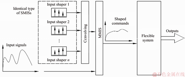
Figure 1 Work flowchart of MMIS
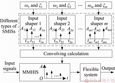
Figure 2 Flowchart of control algorithm of MMHIS
For example, the vibration of the first mode is suppressed by ZV, and the second mode vibration is decreased by ZVD. The parameters of the input shapers are reflected as:

 (20)
(20)
A two-mode hybrid ZV-ZVD can be established via convolving the impulses of these two SMISs.

 (21)
(21)
Some two-mode hybrid input shapers (TMHISs) are established according to convolution with two different kinds of SMISs, such as EI-ZV, EI-ZVD, ZVD-ZV, ZVD-EI, ZV-ZVD and ZV-EI [26].
3 Mechanism and structure of robot
A 3 degree of freedom (3DOF) robot, as shown in Figure 3, is assembled through a moving platform, base and three sets of symmetrical linkages, sliders, linear guides and DC brushless servo motors [27]. There are three DOF in the horizontal plane of the robot. The robot��s coordinate system is demonstrated in Figure 4 to express the motion state of the robot. The deformed and undeformed states of the robot��s linkages are shown, and points OF and OM represent the origin points of the fixed and moving coordinate system, when [��1, ��2, ��3]=[��1, ��2, ��3]=[270��, 30��, 150��], respectively. In the fixed coordinate system, ��i represents the angles between the X axis and the ith linkage, and ��i represents the angles between the X axis and the ith linkage. Each linear displacement mechanism consists of one servo motor and one linear guide. The motor and the linear guide are connected at point Ri, i=1, 2, 3 by a ball screw. A slider is fixed on the linear guide and is driven by the motor to move along the linear guide. Wi is the moving distance of each slider. The motion platform adopts an equilateral triangle structure, T1T2T3. The sliders and the motion platform are connected by the linkages using the revolute joints at points Si and Ti, respectively. In order to obtain sufficient stability, the 3DOF robot is fixed on the foundation. The three linkages are identical in structure size and material. The material of the linkage adopts an aluminum alloy, of which the mass density is 2.77��103 kg/m3 and the elastic modulus is 7.1��1010 N/m2. The dimensions of the linkage are 200 mm (Length), 30 mm (width of cross-section) and 2 mm (height of cross-section). For the moving platform, the distance between any two revolute joints T1T2=T2T3=T1T3=100 mm. The maximum range of linear movement for each slider is 400 mm [14, 27]. By coordinating control of these three server motors, the motion platform of the robot can realize the various motion trajectories, including triangular motion, linear motion, circular motion, etc. The kinematic equation of the 3DOF robot was investigated by our team member, ZHANG [28].

Figure 3 A 3DOF robot
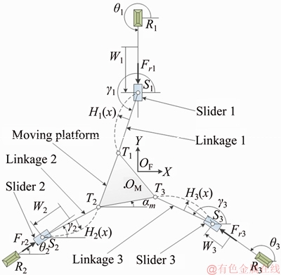
Figure 4 Coordinate system
The light weight linkages are selected for improving motion speed of the robot. However, these components are more likely to lead to greater residual vibration. The trajectory accuracy and motion performance of the robot will be worse. Our previous results show that the dynamic modeling of the robot can be obtained by the Lagrange��s strategy, and the dynamic equations and its derivation process of the robot are investigated by ZHANG et al [27]. According to the experimental model tests of the robot, the former two damping ratios and resonance frequencies are 0.057, 76.6 Hz, and 0.017, 231.2 Hz, respectively [27].
4 Numerical simulations
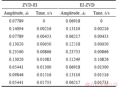
The system��s input signal adopts unit step, and the moving distance of the linkage is 1 mm. Since a single-mode ZV input shaper requires a minimum of two impulses, and ZVD and EI require three impulses, it is a minimum of six impulses to EI-ZV, ZVD-ZV, ZV-EI and ZV-ZVD TMHISs, and at least nine impulses to ZVD-EI and EI-ZVD. The parameters of the first-two-modes�� SMISs of the 3DOF robot are listed in Tables 1 and 2. The parameters of these six TMHISs are listed in Tables 3 and 4, which can be obtained by convolving calculation using the parameters of Tables 1 and 2 [26]. For the TMHISs with EI, the vibration suppression of the robot is less than 5% [25].
Table 1 Parameters of ZV1 and ZV2

Table 2 Parameters of ZVD1, ZVD2, EI1 and EI2
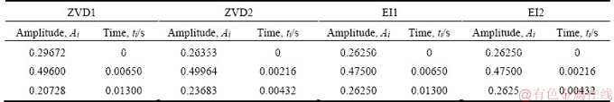
Table 3 Parameters of TMHISs receiving 6 impulses
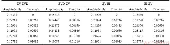
Table 4 Parameters of TMHISs receiving 9 impulses
Upon the simulation, some response curves of the robot linkage with these TMHISs can be obtained. Figure 5(a) shows the response curves of the linkage with and without a ZV-ZVD TMHIS.
As exhibited in Figure 5(a), the residual vibration of the linkage without input shaper is conspicuous when the amplitude of input signal is 1, and it is significantly suppressed when ZV-ZVD is used [26]. In order to analyze the vibration suppression performance of every TMHIS, the response curves of the linkage with various TMHIS are displayed in Figures 5(b)�C(d), moreover, they are compared with two-mode classic input shaper.
As illustrated in Figures 5(b)�C(d), the ZV-ZVD, ZV-EI, EI-ZV, EI-ZVD, ZVD-ZV and ZVD-EI TMHISs are effective to reduce residual vibration. The response curves of the following pairs are very similar: ZV-ZVD and ZV-EI, ZVD-ZVD and ZVD-EI, EI-EI and EI-ZVD [26]. It indicates that the ability to suppress vibration is in the same effect. Moreover, if the vibration of the first mode is suppressed by the identical type of input shaper, and the second mode vibration is decreased by ZV, the response time is faster, but the ability to suppress the amplitude of vibration is weakened. However, if EI is used in the second mode of the two-mode input shaper, the response time is slower, but the ability to suppress the amplitude of vibration is stronger. The response curves of some TMHISs are smoother than that of the classic two-mode input shaper (CTMIS), indicating that the former can suppress more residual vibration. Interestingly, some input shapers have exactly the opposite characteristics. For example, ZV-EI and ZV-ZVD can decrease more vibration than ZV-ZV, while EI-EI and ZVD-ZVD suppress more residual vibration than EI-ZV and ZVD-ZV [26]. For the TMHISs of the 3DOF robot, ZV-EI can decrease the vibration the most, while EI-ZV can decrease the vibration the least. This is mainly determined due to the frequency bandwidth of each mode. Therefore, for the TMHISs, ZV-EI or ZV-ZVD should be selected when the frequency bandwidth of each mode is narrow, and the ZVD-EI or EI-ZVD should be used when the bandwidth is wide.

Figure 5 Response curves:
The response times of ZVD-EI, EI-ZVD, EI-ZV, ZVD-ZV, ZV-EI and ZV-ZVD are 0.0177, 0.0174, 0.0154, 0.0151, 0.0108 and 0.0105 s, respectively. The response times of the system with the CTMIS EI-EI, ZVD-ZVD and ZV-ZV are 0.0179, 0.0171 and 0.0087 s, respectively. The percentages of saved time are shown in Table 5 for comparing response time of between the CTMISs and the TMHISs. For this 3DOF robot, the response time of the system will be reduced by 41.34% if the EI-EI is replaced by ZV-ZVD. However, the response time of the system will be prolonged by 103.45% if ZV-ZV is replaced by ZVD-EI. In addition, the response times of ZV-EI and ZV-ZVD are 0.0021 and 0.0018 s slower than that of ZV-ZV, respectively. But the ZV-ZVD and ZV-EI suppress more residual vibration than ZV-ZV. As to EI-ZV and ZVD-ZV, the response times are 0.0020 and 0.0026 s faster than that with EI-ZVD and ZVD-EI, respectively. But ZVD-ZV and EI-ZV suppress less residual vibration than ZVD-EI and EI-ZVD.
Table 5 Percentages of saved time

Therefore, the most appropriate MMIS or MMHIS is selected on the basis of the required system response time and the frequency bandwidth of each mode [26].
The ability of input shaper to suppress vibration can be assessed through the robustness expressed by the sensitivity curve. The sensitivity curves of various SMISs and TMHISs are displayed in Figure 6.
As illustrated in Figure 6, the first and second order SMISs are valid to reduce the vibration of the corresponding modes, but illustrate less ability of suppressing vibration of other modes. The TMHISs are valid to simultaneously reduce the vibration of the first two modes. As the MMISs are constructed by convolution with multiple SMISs, each SMIS not only reduces the vibration of the corresponding mode, but also suppresses the vibration of other modes. Therefore, the insensitivity of each mode of the MMHIS is greater than that of the corresponding SMIS. The insensitivities of all TMHISs and the SMISs are almost of the same scale in the first-mode. The insensitivities of ZV-ZVD and ZVD2, ZV-EI and EI2 input shapers are slightly different in the second-mode. However, the insensitivities of EI-ZV, EI-ZVD, ZVD-ZV and ZVD-EI are very different than that of the corresponding second order SMIS. This indicates that ZV-ZVD and ZV-EI can fully reflect the abilities and characteristics of vibration suppression of each SMIS. The insensitivities of the EI-ZV, EI-ZVD, ZVD-ZV and ZVD-EI are greater than that of the corresponding SMIS, but the TMHISs increase the response time.
The sensitivity characteristics of the MMHISs can be compared by the sensitivity curves. The sensitivity curves of various TMHISs are shown in Figure 7.
As shown in Figure 7, the frequency bandwidths of the first-mode vibration reduction of the linkage are almost identical when using the same type of input shapers in the first-mode vibration, but the frequency bandwidths of the second-mode vibration reduction are very different due to the use of different types of input shapers. The insensitivities of EI-ZV, EI-ZVD, ZVD-ZV, ZVD-EI, ZV-ZVD and ZV-EI in the first two modes can be obtained by measuring the sensitivity curves widths of every mode at a level of 5% residual vibration. The TMHISs do not reduce vibration to retain below 5% when the errors are more than these insensitivities. For the EI, ZVD and ZV SMISs, the frequency bandwidth of vibration suppression with EI is the broadest, and ZV presents the narrowest frequency bandwidth. This finding is also true in the TMHISs. For the TMHISs of the 3DOF robot, ZVD-EI has the best robustness. The frequency bandwidths of the first two modes are 0.312 and 1.545, respectively. But the response time of ZVD-EI is the longest. In addition, ZV-ZVD has the weakest robustness, but the response of the system is the fastest. The frequency bandwidths of the first two modes are 0.095 and 1.145, respectively.

Figure 6 Sensitivity curves of various SMISs and TMHIS:
5 Conclusions
In this work, the theories of some MMHISs and a 3DOF robot are introduced. A series of TMHISs for the 3DOF robot, including EI-ZV, EI-ZVD, ZVD-ZV, ZVD-EI, ZV-ZVD and ZV-EI, are established under the calculation of the first-two-modes�� damping ratios and resonance frequencies. The numerical simulation demonstrates that these TMHISs are very effective to reduce the first-two-modes�� vibration. The performances of these two-mode classic and hybrid input shapers are compared by response curves and sensitivity curves. The results show that various TMHISs are characterized by different response times and frequency bandwidths of the vibration suppression. The characteristics of vibration suppression of the MMHISs are the same as those of the SMISs. Regardless of the vibration of any mode, the ZV shows the fastest response time, however, the EI shows the best robustness. The percentages of saved time are obtained by comparing the system��s response time between the CTMISs and the TMHISs. As to the TMHISs for the 3DOF robot, ZV-EI decreases vibration the most, while EI-ZV decreases vibration the least. Moreover, ZVD-EI has the best robustness, however, it has the longest response time. ZV-ZVD has the fastest response time, but the robustness is the weakest. Therefore, in order to suppress more residual vibration with a quick response time, the most appropriate MMIS or MMHIS is selected on the basis of the required system response time and the frequency bandwidth of each mode. In the next work, the input shaping control strategies will be combined with the adaptive control and closed-loop control strategies based on the advantages of various input shaping control strategies. The method can switch various input shapers when the robot��s resonance frequency and damping ratio change, which can suppress more residual vibrations more quickly.

Figure 7 Comparison of sensitivity curves of various TMHISs:
References
[1] ZHANG Wei-ze, SOBOLEVSKI A, LI Bing, RAO Yong, LIU Xin-yu. An automated force-controlled robotic micromanipulation system for mechanotransduction studies of drosophila larvae [J]. IEEE Transactions on Automation Science and Engineering, 2016, 13(2): 789�C797. DOI: 10.1109/TASE.2015.2403393.
[2] CHU Zhong-yi, CUI Jing, SUN Fu-chun. Vibration control of a high-speed manipulator using input shaper and positive position feedback [J]. Knowledge Engineering and Management, 2013, 214: 599�C609. DOI: 10.1007/978-3-642- 37832-4_54.
[3] MOHAMED Z, CHEE A K, HASHIM A W I M, TOKHI M O, AMIN S H M, MAMAT R. Techniques for vibration control of a flexible robot manipulator [J]. Robotica, 2006, 24(4): 499�C511. DOI: 10.1016/S0957-4158(03)00013-8.
[4] KAPUCU S, YILDIRIM N, YAVUZ H, BAYSEC S. Suppression of residual vibration of a translating-swinging load by a flexible manipulator [J]. Mechatronics, 2008, 18(3): 121�C128. DOI: 10.1016/j.mechatronics.2007.10. 007.
[5] LAWN M, DI MAURO G, BEVILACQUA R. Guidance solutions for spacecraft planar rephasing and rendezvous using input shaping [J]. Journal of Guidance, Control, and Dynamics, 2018, 41(1): 255�C267. DOI: 10.2514/1. G002910.
[6] ALQADO T E, NIKOLAKOPOULOS G, DRITSAS L. Semi-active control of flexible structures using closed-loop input shaping techniques [J]. Structure Control and Health Monitoring, 2017, 24(5): e1913. DOI: 10.1002/stc.1913.
[7] HILLSLEY K L, YURKOVICH S. Vibration control of a two-link flexible robot arm [J]. Dynamics and Control, 1993, 3(3): 261�C280. DOI: 10.1007/BF01972699.
[8] ARABASI S, MASOUD Z. Simultaneous travel and hoist maneuver input shaping control using frequency modulation [J]. Shock and Vibration, 2017, 1: 1�C12. DOI: 10.1155/2017/ 5703820.
[9] KANG C G, KWAK J H. On a simplified residual-vibration- ratio function for input shaping control [J]. Asian Journal of Control, 2012, 16(1): 277�C283. DOI: 10.1002/asjc.573.
[10] MA K, GHASEMI-NEJHAD M N. Adaptive input shaping and control for simultaneous precision positioning and vibration suppression of smart composite plates [J]. Smart Materials and Structures, 2007, 16(5): 1870�C1879. DOI: 10.1088/0964-1726/16/5/043.
[11] PAI M C. Closed-loop input shaping control of vibration in flexible structures via adaptive sliding mode control [J]. Shock and Vibration, 2012, 19(2): 221�C233. DOI: 10.3233/ SAV-2011-0625.
[12] SINGER N C, WARREN P S. Preshaping command inputs to reduce system vibration [J]. ASME Journal of Dynamic System, 1990, 112(2): 76�C82. DOI: 10.1115/1.2894142.
[13] HUEY J R, SORENSEN K L, SINGHOSE W E. Useful applications of closed-loop signal shaping controllers [J]. Control Engineering Practice, 2008, 16(7): 836�C846. DOI: 10.1016/j.conengprac.2007.09.004.
[14] LI Bing, ZHANG Xu-ping, MILLS J K, CLEGHORN W L, XIE Li-yang. Vibration suppression of a 3-PRR flexible parallel manipulator using input shaping [C]// Proceedings of 2009 International Conference on Mechatronics and Automation. Changchun, China, 2009: 3539�C3544. DOI: 10.1109/ICMA.2009.5246204.
[15] MAGHSOUDI M J, MOHAMED Z, SUNDIN S, BUYAMIN S, JAAFAR H I, AHMAD S M. An improved input shaping design for an efficient sway control of a nonlinear 3D overhead crane with friction [J]. Mechanical System and Signal Processing, 2017, 92: 364�C378. DOI: 10.1016/j.ymssp.2017.01.036.
[16] MAR R, GOYAL A, NGUYEN V, YANG T L, SINGHOSE W. Combined input shaping and feedback control for double-pendulum systems [J]. Mechanical Systems and Signal Processing, 2017, 85: 267�C277. DOI: 10.1016/j.ymssp. 2016.08.012.
[17] KOZAK K, EBERT-UPHOFF I, SINGHOSE W. Locally linearized dynamic analysis of parallel manipulators and application of input shaping to reduce vibrations [J]. Journal of Mechanical Design, 2004, 126(1): 156�C168. DOI: 10.1115/1.1640362.
[18] STERGIOPOULOS J, TZES A. Adaptive input shaping for nonlinear systems: A case study [J]. Journal of Dynamic System, Measurement, and Control, 2007, 129(2): 219�C223. DOI: 10.1115/1.2431815.
[19] KRONEIS J, LIU S. Flexible body modelling and vibration damping for a planar parallel robot using input shaping [C]// Proceedings of 2007 IEEE/ASME International Conference on Advanced Intelligent Mechatronics. Zurich, Switzerland, 2007: 1�C6. DOI: 10.1109/AIM.2007.4412572.
[20] MASOUD Z, ALHAZZA K. Frequency-modulation input shaping for multimode systems [J]. Journal of Vibration and Control, 2016, 22(15): 3439�C3451. DOI: 10.1177/107754631 4560389.
[21] JIA Peng-xiao, LI En, LIANG Zi-ze, QIANG Yan-hui. Adaptive PD control combined with input-shaping for suppressing vibration of a single-mode flexible mechanism [J]. Journal of Vibration and Shock, 2013, 32(17): 189�C193. DOI: 10.3969/j.issn.1000-3835.2013.17. 036. (in Chinese)
[22] PAI M C. Robust input shaping control for multi-mode flexible structures using neuro-sliding mode output feedback control [J]. Journal of Franklin Institute, 2012, 349(3): 1283�C1303. DOI: 10.1016/j.jfranklin.2012.01. 012.
[23] LI Bing, XIE Li-yang, WEI Yu-lan, ZHAO Jin-fang, WANG Lei. Residual vibration suppression of 3-PRR parallel manipulator by multiple-mode input shaping [J]. Machinery, 2010, 48(7): 21�C25. DOI: 10.3969/j.issn.1000-4998.2010. 07.008. (in Chinese)
[24] HUANG Qing, ZHANG Dan, LI Bing, WEI Yu-lan. Vibration suppression of manipulator with multiple-mode negative impulses input shaping [C]// Proceedings of 2012 International Symposium on Chemical Engineering and Material Properties. Taiyuan, China, 2012: 816�C820. DOI: 10.4028/www.scientific.net/AMR.549.816.
[25] WANG Yue-zhan, YAN Qi-bo, LI Bing, WEI Yu-lan. Sensitivity analysis of vibration suppression based on the multiple-mode negative impulses input shapers [C]// Proceedings of 2012 International Conference on Mechatronics and Materials Engineering. Hangzhou, China, 2012: 312�C316. DOI: 10.4028/www.scientific.net/AMM.189. 312.
[26] LI Bing, WEI Yu-lan, ZHU Shou-xin, ZHENG Yu-qing. Hybrid multi-mode input shaping suppresses the vibration of a 3-DOF parallel manipulator [C]// Proceedings of 2011 International Conference on Advanced Engineering Materials and Technology. Sanya, China, 2011: 2115�C2118. DOI: 10.4028/www.scientific.net/AMR.291-294.2115.
[27] ZHANG Xu-ping, MILLS J K, CLEGHORN W L. Dynamic modelling and experimental validation of a 3-PRR parallel manipulator with flexible intermediate links [J]. Journal of Intelligent and Robotic System, 2007, 50(4): 323�C340. DOI: 10.1007/s10846-007-9167-4.
[28] ZHANG Xu-ping. Dynamic modeling and active vibration control of a planar 3-PRR parallel manipulator with three flexible links [D]. Toronto: University of Toronto, 2009. http://hdl. handle.net/1807/19119.
(Edited by FANG Jing-hua)
���ĵ���
���ڶ�ģ̬���ƵĻ���������ο��Ʋ��Լ�С��������
ժҪ�����͵Ķ�ģ̬����������(MMIS)����Чͬʱ��С�����˻��е�ֶ��ģ̬�IJ���������ģ̬��Ƶ���������ϴ�ʱ��MMIS�Ͳ����ڿ�����Ӧ����������IJ��������Ľ����˶��ֵ��͵ĺͻ�Ͽ��Ƶ��������ģ̬�������ο��Ʋ��Լ��乹��ԭ��������������3���ɶȻ����˵���������ģ̬���������������������ֵ�����������Ӧ���ߺ����������ߣ������������������������Ʋ�����������³���ԡ�����-�������㵼��(ZV-ZVD)����Ӧʱ����죬��³������͡��������㵼��-��������(ZVD-EI)��³������ã�����Ӧʱ���������ÿ��ģ̬��Ƶ�����Ⱥ������ϵͳ��Ӧʱ�䣬��ѡ�����ʺϵĶ�ģ̬�������������(MMHIS)���Ӷ�ʵ���ڼ�С��������������¼ӿ�ϵͳ��Ӧʱ�䡣
�ؼ��ʣ���Ͽ��ƣ��������Σ�����ģ̬��������
Foundation item: Project(LQ12E05008) supported by Natural Science Foundation of Zhejiang Province, China; Project(201708330107) supported by China Scholarship Council
Received date: 2018-06-15; Accepted date: 2018-11-02
Corresponding author: LI Bing, PhD, Associate Professor; Tel: +86-572-2320681; E-mail: bingli@zjhu.edu.cn; ORCID: 0000-0003-2799-5936

