激光冲击工艺对6061-T6铝合金侵蚀性能的影响
来源期刊:中国有色金属学报(英文版)2016年第6期
论文作者:J. IBARRA E. RODRíGUEZ O. JIMéNEZ G. GóMEZ-ROSAS M. FLORES J. VERDUZCO J. CHáVEZ
文章页码:1522 - 1530
关键词:6061-T6铝合金;侵蚀磨损;激光冲击工艺
Key words:6061-T6 aluminum; erosive wear; laser shock processing
摘 要:采用激光冲击工艺处理6061-T6铝合金,研究了二氧化硅砂对其侵蚀磨损性能的影响。其中冲击角为15°、30°、60°、90°,粒子速率为37和58 m/s,采用两种激光进行辐照。采用3D轮廓测量法表征了侵蚀形貌,并采用SEM研究其侵蚀机理。结果表明,冲击角较小时,侵蚀磨损最大。侵蚀强度和侵蚀机理不受激光冲击工艺的影响,而与侵蚀的高应变速率有关。侵蚀图之间的差异是由于激光冲击工艺造成的表面粗糙度不同。最大质量损失和最大侵蚀深度分别出现在冲击角度为15°和30°时。最后,发现了明显的侵蚀机理的转移,从低角度的切割机制到90°时的凹坑形成。
Abstract: Application of laser shock processing (LSP) on 6061-T6 aluminum was made in order to evaluate its response to the erosive wear by silica sand. Impact angles of 15°, 30°, 60° and 90° were tested, two particle speeds (37 and 58 m/s) and two LSP irradiation conditions were used. Erosion marks were characterized by 3D profilometry and SEM analysis was conducted to identify the erosion mechanisms for each tested angle. The results showed a maximum erosive wear at low impact angles (ductile type behavior). Erosion strength and the erosion mechanisms were not affected by the application of LSP and they were attributed to the high strain rate of the erosion phenomena. A few differences encountered on the erosion plots were explained on the basis of the surface roughness left by the LSP process. The maximum mass loss and the maximum erosion penetration happened in different impact angles (15° and 30°, respectively). Finally, a well-defined erosion mechanism transition was observed, from cutting action at low impact angle, to crater formation at 90° of incidence.
Trans. Nonferrous Met. Soc. China 26(2016) 1522-1530
J. IBARRA1, E.  1, O.
1, O.  1, G.
1, G.  -ROSAS2, M. FLORES1, J. VERDUZCO1, J.
  1
1
1. Universidad de Guadalajara, Departamento de  de Proyectos,
  Guadalupe Zuno # 48, Zapopan, Jalisco,
  ;
;
2. Universidad de Guadalajara, Departamento de Física, Centro Universitario de Ciencias Exactas e , Blvd Marcelino  # 1421, Guadalajara, Jalisco,
Received 23 July 2015; accepted 21 November 2015
Abstract: Application of laser shock processing (LSP) on 6061-T6 aluminum was made in order to evaluate its response to the erosive wear by silica sand. Impact angles of 15°, 30°, 60° and 90° were tested, two particle speeds (37 and 58 m/s) and two LSP irradiation conditions were used. Erosion marks were characterized by 3D profilometry and SEM analysis was conducted to identify the erosion mechanisms for each tested angle. The results showed a maximum erosive wear at low impact angles (ductile type behavior). Erosion strength and the erosion mechanisms were not affected by the application of LSP and they were attributed to the high strain rate of the erosion phenomena. A few differences encountered on the erosion plots were explained on the basis of the surface roughness left by the LSP process. The maximum mass loss and the maximum erosion penetration happened in different impact angles (15° and 30°, respectively). Finally, a well-defined erosion mechanism transition was observed, from cutting action at low impact angle, to crater formation at 90° of incidence.
Key words: 6061-T6 aluminum; erosive wear; laser shock processing
1 Introduction
Aluminum alloys are corrosion resistant and easy to machining, besides, its low density gives an additional advantage in aeronautics and automotive industries [1]. 6061-T6 aluminum is widely used in the transport industry (automotive and aeronautic), and the artificial aging T6 provides good mechanical properties [2].
Erosive wear occurs due to the repeated impacts of erodent particles in a fluid flow hitting the surface of the material; for example, the aircraft turbine blades while flying through dust clouds [3], thermal power plants and pneumatic transport systems [4], fossil energy plants [5] and carbon processing plants [6]. Erosive behavior can be classified as ductile or brittle, depending on the angle that maximum erosion occurs, as shown in Fig. 1. When the maximum erosion occurs at low impact angles, the material has a ductile behavior; if it occurs at high angles close to 90°, it has a brittle behavior [7].
Erosion is the main reason for the thickness loss of these components. Therefore, it is important to investigate alternative methods to increase the lifetime of materials. The possibility to focus a laser beam over a metal surface, allows local treatments to be carried out, in order to improve the properties of bulk material [8]. Laser shock processing (LSP) is a surface treatment technique used for a wide number of metal and alloys; which was first recognized and explored during the decade of 1960 [9]. This treatment occurs when a high density laser beam impacts the surface of a metallic material [10] generating an expanding plasma due to the solid to vapor transformation on the surface of the material. This plasma generates a shock wave that causes residual stress up to a few millimeters depth in the material, as shown in Fig. 2, as happens in LSP treatments on 6061-T6 aluminum [1,11,12]. Improvements of properties due to LSP treatments have been widely demonstrated in materials such as titanium, copper, aluminum alloys and steels [13]. One of its most important uses is in aeronautic and automotive industries; its benefits are related to fatigue, corrosion and wear resistance [11].
ZHANG et al [14] found that the compressive residual stress can be induced into the surface of specimen, and the fatigue life of the specimen with LSP is 3.5 times as long as that of specimen without LSP in LY12CZ aluminum alloy.  et al [11] found that LSP treatment increases fatigue crack initiation life and reduces fatigue crack growth rate in 6061-T6 aluminum alloy. REN et al [15,16] found a reduction in the effective stress intensity in 7050-T7451 aluminum alloy LSP treated specimens compared to the un-treated ones. REN et al [17] investigated the effects of tempering on surface topography and dislocation configuration of 6061-T651 aluminum alloy by LSP at elevated temperature.
  et al [1] showed that 6061-T6 aluminum reduces its wear rate (roll-on-flat test) about 68% when it is LSP treated with a 5000 pulses/cm2 energy density and 1064 nm wavelength.
According to our knowledge, there is not information regarding erosive wear behavior about 6061-T6 aluminum treated by the LSP technique. Therefore, the aim of the present work is to study the effect of the LSP treatment applied to the 6061-T6 aluminum on its erosive wear response.

Fig. 1 Ductile (1) and brittle (2) erosive wear behaviors
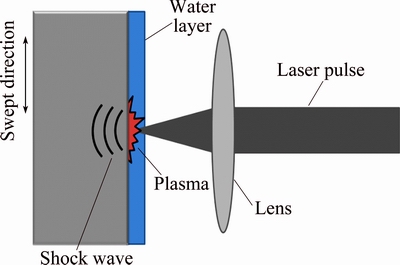
Fig. 2 Schematic of laser shock processing (LSP) principle
2 Experimental
2.1 Specimens preparation
6061-T6 aluminum plate was used to obtain square specimens for high impact angle and rectangular ones for oblique impact. One batch of specimen was surface finished to a roughness less than 1 μm. A second batch of specimens were LSP treated, these were not ground because this process is able to change the residual stress state induced by the surface LSP treatment and they were tested in the as-obtained condition. Its average Ra roughness was 8.2 μm. Figure 3 shows the specimens with and without LSP.

Fig. 3 Specimens with and without LSP treatment
Microstructure was obtained using Barker’s reagent, which is composed of 85 mL H2O, 10 mL H2SO4 and 5 mL HF. Microstructure shows an aluminum matrix with Mg2Si precipitates [18], as shown in Fig. 4.

Fig. 4 Typical microstructure of 6061-T6 aluminum alloy
2.2 Laser shock processing
The LSP experiments reported in this work were performed using a Q switched Nd:YAG laser Brilliant B model, operating at 10 Hz and providing 5 ns FWHM, 440 mJ with a wavelength of 532 nm, and 6 ns FWHM, 880 mJ with a wavelength of 1064 nm. Table 1 shows a summary of these parameters. The confining layer was provided by a water jet incident close to the laser interaction zone. Some authors present residual compressive stress induced by the LSP in aluminum alloys without the use of protective coating [1,11,19,20]. So, no protective coating was applied in the present work. A maximum compressive residual stress below 0.4 mm depth was determined by a co-author in a previous work for aluminum 6061-T6 [1,11]. A 2D motion system was used to control specimen position and generate the pulse swept. Due to limited irradiated area, 15° erosion tests were omitted in LSP treated specimens.
Table 1 LSP irradiation parameters used on 6061-T6 aluminum alloy

2.3 Erosion tests
Erosion tests were carried out according to ASTM G76-95 [21] using a sand-blast type machine, which is schematically shown in Fig. 5. On this configuration, sand is poured into a superior chamber that allows the sand to pass to an inferior chamber where a pressurized mixture of air and sand is generated. The mixture travels through an outlet nozzle to hit the specimen which is tilted to a specified angle. Impact distance was set to 25 mm. Nozzle inner diameter was 2 mm and it was replaced when it increases in 10% according to Ref. [21]. 150 μm silica sand was used as erodent, its morphology and particle size are shown in Fig. 6. Dry air flux with a dew point of -45 °C was used as carrier fluid. Specimens were impacted at 15°, 30°, 60° and 90° and blow pressures of 6.895 and 20.685 kPa. Each condition was repeated at least 3 times obtaining an average error of 3.2%.
Specimens were cleaned before and after the test with acetone in an ultrasonic bath for 10 min, their mass losses were determined using a 0.1 mg precision analytical balance. The erosion rate was measured dividing the total removed mass (g) by the particles total mass (kg).
The particles speed was measured by the double disc method (DD) [22], the results were 37 and 58 m/s corresponding to pressures of 6.895 and 20.685 kPa, respectively.

Fig. 5 Schematic of erosion testing machine

Fig. 6 Size and shape of silica sand
Erosion mechanisms were identified by FESEM, and specimens were tilted 40° in order to have a better topographic view of the eroded zone. A Veeco Dektak 150 profilometer was used to get 3D images of the eroded mark zone, and the surface roughness values.
3 Results and discussion
3.1 Erosion marks
Figure 7 shows photographs of the wear marks generated by the silica sand impacts for each angle and pressure used. At 15° and 30° impact angles, an elliptical shape mark is created with an eccentricity of 0.93 and 0.81, respectively; at a 60° impact angle, the mark is still elliptical but with a decrement in its eccentricity of 0.43; and at 90° impact angle, the erosion mark has a circumferential shape. In all cases, pressure did not have influence on the shape of the generated mark.

Fig. 7 Erosion wear marks
3.2 Erosion behavior
In all cases, a ductile behavior was observed. Figure 8 shows an erosion rate vs impact angle at 6.895 kPa drag pressure for both specimens with and without LSP. It can be observed that there is a decrease in erosion strength of the specimens treated with LSP, mainly in the 5000 pulses/cm2 condition (λ=1064 nm). The biggest difference in erosion rate as a function of the impact angle (Points 1 and 2 in Fig. 8) was observed at 30°, followed by the 60° impact angle (Points 3 and 4) and finally, there is a convergence in erosion values when approaching to normal incidence angle (90°).

Fig. 8 Plot of erosion vs impact angle at blow pressure of 6.895 kPa
The difference in erosion of the samples impacted at 30° shown in Fig. 8 (Points 1 and 2; 0.0015 g), can be explained on the basis of the initial roughness of the LSP treated sample (8.2 μm, Ra). For this specimen, the surface presented hills and valleys as shown in Fig. 9 and for this angle the initial roughness is important because the erosion mechanism has a large amount of cutting action. This cutting action is the result of a major tangential component during the impact, capable to cause larger mass detachment in a material that presents ductile behavior as it is shown for this case. The cutting capability decreases as the impact angle increases.
Figure 10 shows 3D images of the topography and maximum erosion depth of specimens tested at 30°, 60°and 90° at 6.895 kPa pressure. The eroded mass due to the initial surface roughness can be calculated based on the erosion mark ellipse (Fig. 10(b)) with the depth between the hills and valleys of 31.9 μm (see Fig. 11). For the 30° impact angle, a mass of 0.0014 g is obtained, which is comparable with the difference in erosion mass of 0.0015 g for this case.

Fig. 9 Roughness after LSP treatment
Similarly, in the case of 60° impact angle (points 3 and 4 in Fig. 8) with an eroded elliptical surface area shown in Fig. 10(d), the mass calculated of the hills and valleys is 0.0010 g, which is very close to the mass difference 0.0011 g.
At 90° (points 5 and 6 in Fig. 8), the mass calculated is 0.0004 g and similarly it can be explained by the minor eroded area, as shown in Fig. 10(f), but mainly because this impact angle does not have the tangential component, then, the initial surface condition shown in Fig. 9 has a lower effect. That is, the hills formed by the LSP treatment are easier to remove for a low impact angle. At 90° impact angle only craters are formed, as it will be discussed in Section 3.3. The lower wear values for the ductile behavior is explained by the fact that the normal impact expends a lot of energy in such a plastic deformation that not necessarily detaches metal.
Figure 12 shows that no difference exists between erosion amount for specimens with and without LSP treatment, at 20.685 kPa blow pressure for each impact angle. For this case, the erosion rate at lower impact angles did not show a significant difference. The ratio of total removed mass to the contained mass in the hills and valleys by the LSP is in the order of 24 times which makes the initial surface effect negligible.
The discussion above makes to conclude that there is no difference in erosion resistance in Al 6061-T6 alloy in the as-received condition and after LSP treatment. The differences are found due to the initial surface condition. et al [1] found that LSP treatment in 6061-T6 alloy reduces its wear rate (roll on flat test) by about 68%; however, a reduction in erosive wear rate for impact angles, pressures and laser irradiation parameters tested in the present research did not show any improvement. This can be attributed to the high strain rate of the erosion phenomena (typical values lie in the range of 104-107 s-1 [4], which implies that the plastic deformation occurs under adiabatic conditions, leading to an increase in temperature of the eroded material. This increase was calculated by CHEN et al [23] leading to a maximum ΔTmax of 365 K for aluminum, under ideally adiabatic conditions. We believe that the heat generated by the adiabatic conditions could be good enough to relief the residual stresses induced by the LSP treatment, although, additional experimental work is necessary in order to confirm this hypothesis. On the other hand, the strain rate values in the sliding wear lie in the order of 10-1 s-1 and thus, no adiabatic process occurs; this means that the heat produced during this process is able to be dissipated.
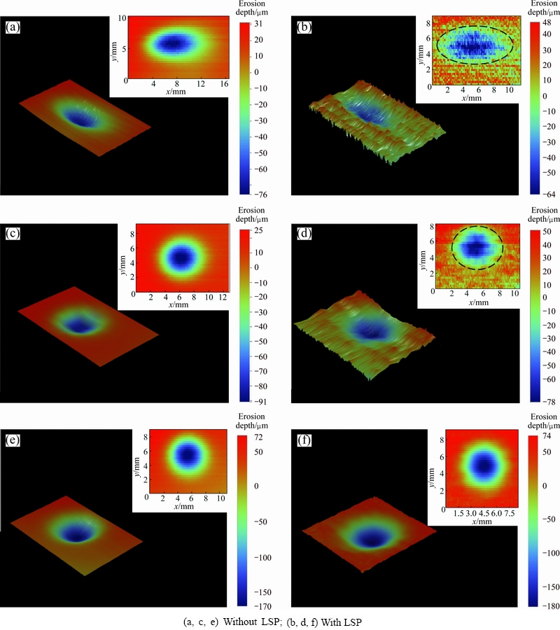
Fig. 10 Erosion marks at 30° impact angle (a, b), 60° impact angle (c, d) and 90° impact angle (e, f)
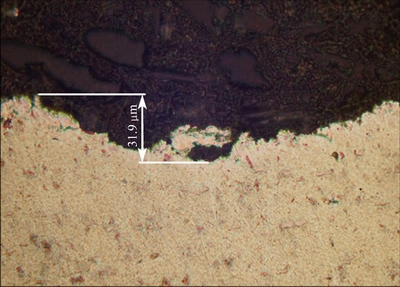
Fig. 11 Roughness after LSP treatment
LAGUNA-CAMACHO et al [24] reported a ductile behavior for 6061-T6 aluminum whose maximum erosion is at 30°, being the lower angle tested. In the present study, the lower angle tested was 15° which corresponds to the maximum erosion rate; therefore, it should be taken into account for this trend that the maximum erosion rate could be even at lower angle than what is here shown.
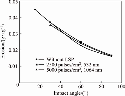
Fig. 12 Plot of erosion vs impact angle at 20.685 kPa blow pressure
Figure 13 shows the maximum erosion depth penetration for both impact particle speeds of 37 and 58 m/s (6.895 and 20.865 kPa, respectively). It is observed that the maximum penetration values occurred at 30°, whereas the 15° angle corresponds to the maximum mass loss. Then, there is no correspondence between the angle of maximum erosion and the angle of maximum penetration depth, which is important for applications where the thickness loss defines the useful lifetime of the metallic component.

Fig. 13 Maximum erosion depth penetration on specimens without LSP treatment
The laser shock processing induces a residual stress field up to a depth of 1 to 2 mm [1,11,15] which is greater than the maximum erosive scar depth (550 μm) found in this study. Thus, all the erosive scars lie within the residual stress field induced by the LSP.
3.3 Wear mechanisms
The wear mechanism on the eroded specimens without LSP treatment impacted at 15°, 30°, 60° and 90° using a particle speed of 58 m/s is described as follows.
Figure 14 shows the erosion caused by impacts at 15°, it can be noticed that cutting action made by erosive particles is the main reason of material removal typical for impact at low angles. The tangential component of the particle speed has a greater contribution than the normal component, generating the formation of grooves with some plastic deformation in lateral lips shape or frontal lips shape in the erodent flow direction.
Figure 15 shows the erosion mechanism caused by 30° angle impacts. In comparison with erosion at 15°, it can be noticed that cutting action has decreased but the formation of grooves is still part of the erosion mechanism, but these are shorter. However, plastic deformation has increased considerably in the form of lateral and mainly frontal lips which are susceptible to be detached by subsequent impacts.
The erosion surface at 60° impact angle is shown in Fig. 16. There is a considerable increment of the plastic deformed material, in such a grade that the groove mechanism is not clearly identified. Some indentations with a symmetrical shape can be noticed, which can be attributed to the erosion ellipse eccentricity close to the cero value.

Fig. 14 Erosion surface without LSP treatment at particle speed of 58 m/s (6.895 kPa blow pressure) and 15° impact angle
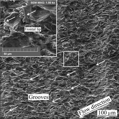
Fig. 15 Erosion surface without LSP treatment at particle speed of 58 m/s (20.685 kPa blow pressure) and 30° impact angle
Figure 17 shows the erosion surface at 90°. Because there is only normal component of the particle speed, it causes damage on the surface by the formation of craters and displacement of material around the impact point. Subsequent impacts cause the detachment of ulterior material which is the principal wear mechanism typical for ductile materials at this erosion angle.
Figure 18 shows the erosion mechanisms for the case of the LSP treated samples. There was no difference found on the wear mechanism in specimens with and without LSP at the two particle speeds used. This result is attributed to the adiabatic conditions of high strain rate of the erosion phenomena, as it was explained previously.
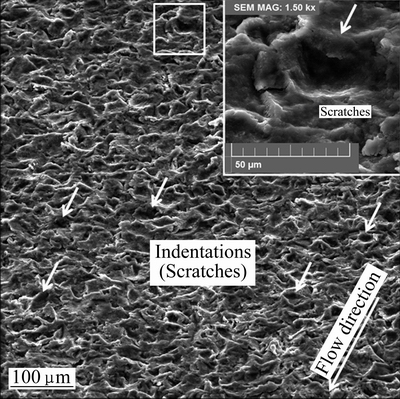
Fig. 16 Erosion surface without LSP treatment at particle speed of 58 m/s (20.685 kPa blow pressure) and 60° impact angle

Fig. 17 Erosion surface without LSP treatment at particle speed of 58 m/s (20.685 kPa blow pressure) and 90° impact angle
4 Conclusions
1) There is no difference in erosion resistance of 6061-T6 aluminum attributed to the LSP treatment, and the differences found are due to the initial roughness left by the LSP treatment.
2) Although the maximum mass loss caused by erosion is at 15°, the maximum erosion depth occurs at 30° impact angle. A ductile behavior is observed in all cases.
3) The erosion mechanisms observed for the tested angles are: at 15°, grooves formation due to the mayor contribution of the tangential component of the particles speed, and some plastic deformation in the metal; at 30°, the metal plastic deformation increases considerably forming lateral and frontal lips. The cutting action has decreased and grooves formation is still present but these are shorter; at 60°, there is a considerably increment in the plastic deformation of the metal and groove formation mechanism is not observed. At 90°, surface damage is due to craters formation causing metal displacement around the impact and the subsequent impacts causes the detachment of the material. The erosion mechanisms are the same for the samples with or without LSP treatment, as well as for the two particle speeds of 37 and 58 m/s.

Fig. 18 Erosion surface with LSP treatment at particle speed of 58 m/s (20.685 kPa blow pressure)
Acknowledgements
The authors wish to acknowledge financial support from CONACYT.
References
[1] SANCHEZ-SANTANA U, RUBIO-GONZALEZ C, GOMEZ- ROSAS G,  J L, MOLPECERES C, PORRO J A, MORALES M. Wear and friction of 6061-T6 aluminum alloy treated by laser shock processing [J]. Wear, 2006, 260(7-8): 847-854.
[2] AMBRIZ R R, CHICOT D, BENSEDDIQ N, MESMACQUE G, de LA TORRE S D. Local mechanical properties of the 6061-T6 aluminum weld using micro-traction and instrumented indentation [J]. European Journal of Mechanics-A/Solids, 2011, 30(3): 307-315.
[3] STACHOWIACK G W, BATCHELOR A W. Engineering tribology [M]. 3rd ed. United States of America: Elsevier Butterworth- Heinemann, 2005.
[4] SUNDARARAJAN G. The solid particle erosion of metallic materials: The rationalization of the influence of material variables [J]. Wear, 1995, 186-187: 129-144.
[5] ADLER T A, RAWERS J C, TYLCZAK J H. Erosive wear of selected materials for fossil energy applications [R]. Albany Research Center, U.S. Department of Energy, 2001.
[6] MCDONALD G, KELLEY J. Erosive wear of potential valve materials for coal-conversion plants [R]. US Department of the Interior, 1994.
[7] HUTCHINGS I M. Tribology, friction and wear engineering materials [M]. USA: Elsevier Butterworth-Heinemann, 2003.
[8]  B J, VARELA R, GARCIA I, de DAMBORENEA J. Laser heat treatment of steel cutting blades for agricultural uses [J]. Rev. Metal, 2003, 39: 443-451.
[9] DINK K, YE L. Laser shock peening Performance and process Simulation [M]. Cambridge, England: Woodhead Publishing in Materials, 2006.
[10] HU Yong-xiang, LI Kang-mei, QI Chen-jie, YAO Zhen-qiang, GRANDHI R V. Size effect on indentation depth of oxygen-free high purity copper induced by laser shock processing [J]. Transactions of Nonferrous Metals Society of China, 2012, 22(S2): s573-s578.
[11] RUBIO-GONZALEZ C, J L, GOMEZ-ROSAS G, MOLPECERES C, PAREDES M, BANDERAS A, PORRO J A, MORALES M. Effect of laser shock processing on fatigue crack growth and fracture toughness of 6061-T6 aluminum alloy [J]. Materials Science and Engineering, 2004, 386(1-2): 291-295.
[12] GOMEZ-ROSAS G, RUBIO-GONZALEZ C, J L, MOLPECERES C, PORRO J A, MORALES M, CASILLAS F J. Laser shock processing of 6061-T6 Al alloy with 1064 nm and 532 nm wavelengths [J]. Applied Surface Science, 2010, 256(20): 5828-5831.
[13] NIEHOFF H S, VOLLERTSEN F. Laser induced shock waves in deformation processing [J]. Association of Metallurgical Engineers Serbia and Montenegro, 2005, 11(3): 183-194.
[14] ZHANG Xing-quan, CHEN Liu-san, YU Xiao-liu, ZUO Li-sheng, ZHOU Yu. Effect of laser shock processing on fatigue life of fastener hole [J]. Transactions of Nonferrous Metals Society of China, 2014(4), 24: 969-974.
[15] REN X D, ZHAN Q B, YANG H M, DAI F Z, CUI C Y, SUN G F, RUAN L. The effects of residual stress on fatigue behavior and crack propagation from laser shock processing-worked hole [J]. Materials and Design, 2013, 44: 149-154.
[16] REN X D, ZHANG Y K, ZHANG T, JIANG D W, YONGZHUO H F, JIANG Y F, CHEN K M. Comparison of the simulation and experimental fatigue crack behaviors in the nanoseconds laser shocked aluminum alloy [J]. Materials and Design, 2011, 32(3): 1138-1143.
[17] REN X D, RUAN L, YUAN S Q, REN N F, ZHENG L M, ZHAN Q B, ZHOU J Z, YANG H M, WANG Y, DAI F Z. Dislocation polymorphism transformation of 6061-T651 aluminum alloy processed by laser shock processing: Effect of tempering at the elevated temperatures [J]. Materials Science and Engineering A, 2013, 578: 96-102.
[18] STEVENS H. ASM metals handbook: Metallography and microstructures [M]. Vol. 9. USA: ASM International, 1992.
[19] SANO Y, AKITA K, MASAKI K, OCHI Y, ALTENBERGER I, SCHOLTES B. Laser peening without coating as a surface enhancement technology [J]. Journal of Laser Micro/ Nanoengineering, 2006, 1-3: 161-166.
[20] J L, MOLPECERES C, PORRO J A, GOMEZ G, MORALES M. Experimental assessment of the influence of irradiation parameters on surface deformation and residual stresses in laser shock processed metallic alloys [J]. Appl Surf Sci, 2004, 238: 501-505.
[21] ASTM G-76-95. Conducting erosion tests by solid particle impingement using gas jets [S]. 2000.
[22] LEVY A V. Solid particle erosion and erosion-corrosion of materials [M]. USA: ASM International, 1995.
[23] CHEN D, SARUMIM, AL-HASSANI S T S, GANS, YIN Z. A model for erosion at normal impact [J]. Wear, 1997, 205: 32-39.
[24] LAGUNA-CAMACHO J R, CRUZ-MENDOZA L A, ANZALMETTI-ZARAGOZA J C,  A, VITE-TORRES M,
  J. Solid particle erosion on coatings employed to protect die casting molds [J]. Progress in Organic Coatings, 2012, 74(4): 750-757.
J. IBARRA1, E. 1, O. 1, G. -ROSAS2, M. FLORES1, J. VERDUZCO1, J. 1
1. Universidad de Guadalajara, Departamento de de Proyectos, Guadalupe Zuno # 48, Zapopan, Jalisco, ;
2. Universidad de Guadalajara, Departamento de Física, Centro Universitario de Ciencias Exactas e , Blvd Marcelino # 1421, Guadalajara, Jalisco,
摘 要:采用激光冲击工艺处理6061-T6铝合金,研究了二氧化硅砂对其侵蚀磨损性能的影响。其中冲击角为15°、30°、60°、90°,粒子速率为37和58 m/s,采用两种激光进行辐照。采用3D轮廓测量法表征了侵蚀形貌,并采用SEM研究其侵蚀机理。结果表明,冲击角较小时,侵蚀磨损最大。侵蚀强度和侵蚀机理不受激光冲击工艺的影响,而与侵蚀的高应变速率有关。侵蚀图之间的差异是由于激光冲击工艺造成的表面粗糙度不同。最大质量损失和最大侵蚀深度分别出现在冲击角度为15°和30°时。最后,发现了明显的侵蚀机理的转移,从低角度的切割机制到90°时的凹坑形成。
关键词:6061-T6铝合金;侵蚀磨损;激光冲击工艺
(Edited by Yun-bin HE)
Corresponding author: J. IBARRA; Tel: +52-33-36035964; E-mail: jose.ibarra@itszapopan.edu.mx
DOI: 10.1016/S1003-6326(16)64258-9

