
Dissolution mechanism of solid nickel in liquid zinc saturated with Fe
KONG Gang(孔 纲), LU Jin-tang(卢锦堂), XU Qiao-yu(许乔瑜)
School of Materials Science and Engineering, South China University of Technology, Guangzhou 510640, China
Received 25 July 2006; accepted 23 March 2007
Abstract: The dissolution behavior of solid nickel in static liquid zinc saturated with Fe at 723 K was studied. The results show that when immersing solid Ni in liquid Zn saturated with Fe, the intermetallic compound layers consisted of γ and δ phases are formed on nickel substrate, which is the same as that in liquid pure zinc. However, some Γ2 particles are formed in the liquid near the solid/liquid interface. These Γ2 particles can easily heterogeneously nucleate on ζ particles and grow fast. The dissolution process is governed by diffusion of nickel atom across a concentration boundary layer in liquid Zn saturated with Fe, and is different from a mixed control mechanism of nickel in liquid pure zinc. The participation of Γ2 particles makes the dissolution of solid Ni in the liquid accelerated.
Key words: solid nickel; liquid zinc; dissolution mechanism
1 Introduction
Interfacial interaction between solid and liquid metals is of importance in the technology of materials surface treatment and metallurgy process, such as hot dip galvanizing, welding, and smelting[1-3]. Recently, the smelting process of Zn-Ni master alloys and the direct alloying technology of Ni-Zn[4-5] are developed suitable for technigalva[6] that has been widely used in hot dip galvanizing on reactive steel (0.06%-0.12%Si) [7], and nickel-based pretreatments have been studied to solve the problems of hot dip galvanizing on high silicon steel (>0.25%Si)[8]. When immersing solid nickel in liquid zinc, dissolution of the solid in liquid phase and formation of intermetallic compound layers at the interface take place simultaneously. In previous work[9], the dissolution behavior of solid nickel in liquid pure zinc under natural conventional condition was reported and the conclusion that the dissolution process is governed by a mixed control mechanism involving diffusion of nickel atom in Ni-Zn intermetallic layers and the interfacial reaction between solid nickel and liquid zinc at 723 K is drawn. At temperatures of 823 and 923 K, the dissolution rates would be controlled by diffusion of nickel atom across a concentration boundary layer in liquid zinc. However, in an industrial hot dip galvanizing process, iron and steel are dipped into a molten zinc bath, reacted with liquid zinc and dissolved in the zinc bath continuously. The zinc bath used is always over-saturated with Fe. The solubility of Fe in liquid Zn is about 0.03% (mass fraction) at 723 K[10], and the excess Fe in a zinc bath participates Fe-Zn compound ζ(FeZn13) as dross that settles in the bath and at the bottom of the bath eventually[11]. Though some investigations[5,9,12-13] have been taken to evaluate the kinetics of dissolution of solid nickel or nickel alloy in liquid zinc, there appears to be little information concerning the dissolution of solid nickel in liquid zinc saturated with Fe, and the effect of saturated Fe on the interfacial reaction between solid nickel and liquid zinc are not well understood.
In the present work, an attempt has been made to elucidate the mechanism of the dissolution of solid nickel in liquid zinc saturated with Fe under natural convection. The growth of intermetallic compound layers at solid/liquid interface, and the change of intermetallic compound particles in the liquid layer near solid/liquid interface were observed. The dissolution model associated with intermetallic compound layers formation and the nondimensional correlation for mass transfer under natural convection condition was applied to estimate the rate-determining step in the dissolution process. And the difference of the dissolution mechanisms of solid nickel in liquid zinc saturated with Fe and liquid pure zinc were discussed. It is useful in interpreting the dissolution process relevant to Ni-Zn direct alloying technology and hot dip galvanizing on the steel with nickel-based pretreatments.
2 Experimental
Electrolytic-grade nickel wire (99.5%Ni) and special high grade(SHG) zinc ingot (99.995%Zn) were employed for the investigation. The size of the nickel specimens was 1 mm in diameter and 50 mm in length. Zn-5%Fe master alloy was prepared in advance to adjust the added iron in molten zinc. 96 g zinc and 4 g Zn-Fe master alloy were weighted accurately to ensure to obtain the saturated concentration of Fe in the melt and the total mass of the melt was 100 g. The experiment was carried out at 723 K, considered to be the typical temperature of hot dip galvanizing process. The experimental procedure same as that in the pervious work[9] was as follows.
To heat the melt in a 30 mL corundum crucible to the required temperature and to maintain it, an electric-resistance furnace was employed. Temperature was measured with a calibrated chromel-alumel thermocouple. During the reaction time for a given specimen the temperature of the melt varied in ±2 K maximum. Argon was used to protect the melt from oxidation by atmospheric air. When the equilibrium temperature was reached, a Ni specimen was dipped vertically into the melt through a hole in the center of the lid of the crucible, the lid acting as a support. The dipping depth of the Ni specimen was 30 mm. Before dipping the Ni specimen was degreased in a 30%NaOH solution, and fluxed in a 20 g/L ZnCl2+20 g/L NH4Cl aqueous solution at 333 K, then dried in hot air. The reaction time was begun to count when the Ni specimen dipped into the melt. After a predetermined reaction time (30-600 s), the crucible, together with the melt and the Ni specimen, was taken out from the furnace and cooled in circling water, corresponding to a cooling rate of about 30 K/s measured by dipping a micro-thermocouple in the middle of the melt. After cooling, a cross-section of a bimetallic specimen at the middle part of the ingot was obtained, and then polished and etched by a solution of 15 mL H2O2+85 mL NH3?H2O to reveal the intermetallic compound layers at the solid/liquid interface.
Specimens were observed by both optical microscope and SEM. The thickness of the intermetallic compound layers and average size of intermetallic particles were measured by SEM. EDS analysis on the Ni-Zn transition zone that included the intermetallic compound layers and the particles was also carried out to determine the chemical composition.
3 Results and discussion
3.1 Morphology and characteristics of Ni-Zn transi- tion zone
Like that in the liquid pure zinc, when nickel specimen is dipped into the melts, two intermetallic compound layers are formed on the nickel substrate and get thicker with increasing of the immersion time. It is different from that in liquid pure zinc that some intermetallic particles are found to be formed in the liquid layer near the solid/liquid interface, and the amount and the size of particles are increased with the increase of immersion time. Fig.1 shows the back- scattered electron images of the Ni-Zn transition zone from liquid zinc saturated with Fe for 1 800 s, and the chemical composition and consisting phases of the points Intermetallic compound layers on surface of nickel substrate; (c) Microstructure of intermetallic particles near solid/liquid interface
in Fig.1 are shown in Table 1 and Fig.2 in terms of EDS results and Fe-Zn-Ni ternary phase[14]. As seen from Fig.1(a), the dark black circle at the center of the image is the cross-section of the cylinder nickel, on which a bright white ring is Ni-Zn intermetallic compound layer. Further observation on the intermetallic compound layer (Fig.1(b)), it is found that the bright white ring consists of a thin layer of γ phase (A point in Fig.1(b)) in contact with the nickel, and an intermetallic layer of δ phase (B point in Fig.1(b)) adjacent to the zinc. It can be distinguished that there is another very thin layer (about 1 μm) between the nickel and γ phase layer, its chemical composition is 26.57%Ni and 73.43%Zn (molar fraction) and still within the homogeneity range of γ phase[15]. Actually, these two layers of γ phase have an inverse antiphase domain structure[15]. It can be seen from Fig.1(b) that many cracks occur in both layers. Layer cracking appears to be a result of the difference in thermal expansion coefficients of these phases[16]. So it can be seen that the morphology and phase consisted of the Ni-Zn intermetallic compound layers are the same as those in liquid pure zinc[9].

Fig.1 Microstructures of Ni-Zn transition zone in liquid Zn saturated with Fe: (a) Backscattered electron image of transition zone; (b)
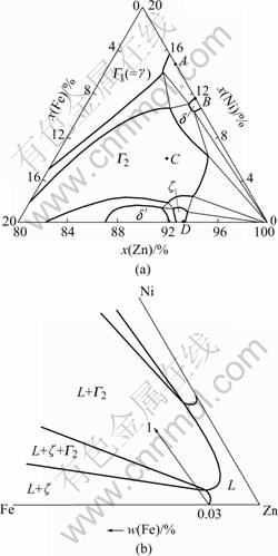
Fig.2 Zinc-rich corner of Fe-Zn-Ni ternary diagram at 450 ℃ [14]: (a) x(Zn)=0.8-1.0; (b) Liquid zinc region
Table 1 EDS results for Ni-Zn transition zones in Fig.1
Significantly different from that in liquid pure zinc, many big irregular polygon white Γ2 ?phase particles are found to be formed around the nickel circle in the zinc base(Fig.1(a)). The size of the particles is about 40-100 μm. Some tiny grey long particles of ζ phase in outer area form the Γ2 phase zone in zinc base, of which the size is about 5-20 μm. Further observation on the intermetallic particles is shown in Fig.1(c). As seen from Fig.1(c), a small ζ phase particle as the nucleating center is enclosed by a big irregular polygon Γ2 particle (C point in Fig.1(c)), and other Γ2 particles are linked with many ζ particles (D point in Fig.1(c)).
Thus it can be seen that the dissolution process of solid nickel in liquid zinc saturated with Fe is accompanied by the formation of Γ2 phase particles, in addition to the formation of the intermetallic compound layers at the solid/liquid interface. According to the zinc-rich corner of Fe-Zn-Ni ternary system (Fig.2(b)), the melt is saturated with iron and has the iron concentration of 0.03% (mass fraction). When immersing nickel in the melt, the liquid phase layer near the solid/liquid interface enters into (L+ζ) phases regionFirstly, in which the nickel concentration increases continuously? and ζ phase particles are participated, and then enters into (L+ζ+Γ2) phases region and (L+Γ2) phases region successively, following the direction of arrow 1 illustrated in Fig.2(b). It is possible for Γ2 phase to heterogeneously nucleate on either ζ phase participated from the liquid phase or ζ dross particles floated in this liquid phase layer and get enough iron atoms to grow due to the high content of Fe in ζ phase (about 5%-6%Fe)[11]. So Γ2 phase can be easy to heterogeneously nucleate and grow fast.
3.2 Dissolution kinetics of solid nickel in liquid zinc saturated with Fe
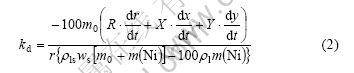
Like in liquid pure zinc[9], the intermetallic compound layers consisted of γ and δ phases are formed while the nickel specimen is dissolved in liquid zinc saturated with Fe. The dissolution process is illustrated in Fig.3, and the general dissolution rate equation is the same as that in liquid pure zinc[9] and can be expressed by
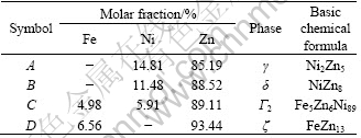
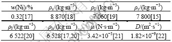
where w is the mass fraction of the dissolved material in the melt; kd is the dissolution rate constant, m/s; A is the area of the solid/liquid interface, m2; V is the liquid volume, m3; ρls is the density of saturated concentration, kg/m3; ρl is the density of bulk liquid concentration, kg/m3; ws is the mass fraction of the solute at saturated concentration.
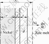
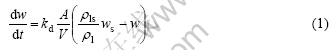
Fig.3 Schematic illustration of dissolution of nickel in melts
On dissolving of solid nickel into liquid zinc with the formation of intermetallic compound layers at the solid/liquid interface, the total amount of nickel consumption includes the amount of dissolved nickel in the melt (including Γ2 phase particles) and that of remained nickel in the intermetallic layers according to the law of mass conservation. Like in the liquid pure zinc[9], same form of the expression equation of the dissolution rate constant kd in the liquid zinc saturated with Fe can be derived as follows:
where
m(Ni)=πh[ρs(r02-r2) -0.1ρδx(2r+2y+x) -0.2ργ y(2r+y)]
R=ρsr+0.1ρδx+0.2ργ y
X=0.1ρδ(r+x+y)
Y= 0.1ρδx+0.2ργ(x+y)
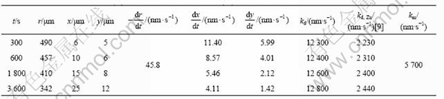
The mass of the bulk liquid m0 is 0.1 kg; the data of r, x, y are taken from the experiments, dr/dt, dx/dt and dy/dt can be derived from the experimental data by fitting curve, and the other characteristic values are listed in Table 2. Due to the low saturated concentration of Fe in the melt (only about 0.03%, mass fraction), the dissolution rate constant kd is calculated and listed in Table 3 by ignoring the effect of Fe in the melt. The dissolution rate constant in liquid pure zinc kd, Zn is taken from Ref.[9] and also listed in Table 3.
Table 2 Values of physical properties
On the other hand, the same experimental method as in the pervious work[9] was carried out in this study. When a vertical solid specimen is unstirred and immersed in a static liquid, a binary solution is formed near the dissolution front, and significant concentration- induced density gradients may develop in a region near the solid substrate. Under the influence of gravity, the concentration-induced density gradients create a strong buoyancy force that causes the dissolved material to move in the vertical direction, thus resulting in a convective flow in the liquid and the development of a dissolution boundary layer adjacent to the interface[23]. A nondimensional correlation for mass transfer under natural convection condition can be applied to this study as follows:
Sh=0.13(Grm?Sc)1/3 (3)
where Sh, Grm and Sc are Sherwood number, Grashof number and Schmidt number respectively.
The mass transfer coefficient km calculated theoretically from Eqn.(3) is given by the following equation:
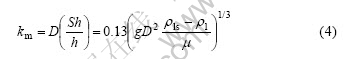
where the mass transfer coefficient km is the mass flux of solute at unit concentration difference between the solid/liquid interface and the bulk liquid, m/s; D is the diffusion coefficient of solute in liquid metal, m2/s; h is the length of the nickel specimen immersed in the melt, 0.03 m; g is the gravity acceleration, 9.8 m/s2; other characteristic values are listed in Table 2. Physically, the mass transfer coefficient km equals the dissolution rate constant kd if the dissolution process is controlled by mass transfer of solute in liquid metal[23]. Thus km is calculated from Eqn.(4) by ignoring the presence of Fe in liquid zinc and indicated in Table 3.
Table 3 Dissolution rate constant (kd) and mass transfer coefficient (km) of solid nickel in zinc melt
The dissolution process with the formation of intermetallic compound layers at the solid/liquid interface commonly includes the following steps:
1) Reaction at the solid substrate/intermetallic compound layer interface;
2) Formation of intermetallic compound layers and diffusion in the layers;
3) Interfacial reaction between the intermetallic compound layer and the liquid metal;
4) Diffusion across a concentration boundary layer in the liquid metal.
The dissolution rate may be governed by one or more of these steps. It can be presumed that, if kd is nearly equal to km, diffusion across a concentration boundary layer in the liquid metal, namely, step 4), is a possible limiting step. If kd is less than km, one or more of steps 1)-3) may dominate the dissolution rate, which means the influence of the formation of intermetallic compound layers cannot be ignored.
It can be concluded from Table 2 that the dissolution mechanism of solid nickel in liquid zinc saturated with Fe is significantly different from that in liquid pure zinc. In liquid pure zinc, kd, Zn is less than km, which means the dissolution process is governed by a mixed control mechanism involving nickel atom in the intermetallic compound layers and the chemical reaction between solid and liquid[9].
In liquid zinc saturated with Fe, kd is larger that km. Based on the four steps of the dissolution process, it is impossible that the dissolution rate constant kd is larger than the mass transfer coefficient km. So it is presumed that the influence of saturated concentration of iron cannot be ignored to calculate km from Eqn.(4). It can be interpreted by means of the concentration boundary layer theory of the dissolution of solid metal in liquid metal under natural convection condition[23] (Fig.4). Assuming the thickness of the concentration boundary layer at the solid/liquid interface is d, the mass transfer coefficient km is expressed as[24]
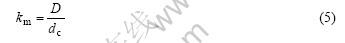
where dc is the effective thickness of concentration boundary layer. As seen from Fig.4, in the concentration boundary layer, the concentration of nickel decreases gradually with increasing of the distance x from solid substrate. Because the intermetallic compound layer adjacent to the liquid is still δ phase in liquid zinc saturated with Fe, the saturated concentration of nickel at the solid/liquid interface cs2 is considered as same as that in liquid pure zinc cs1. However, due to the formation of Γ2 phase, the nickel concentration goes down and a high concentration gradient of nickel is formed, i.e., the effective thickness of concentration boundary layer, dc2, in liquid zinc saturated with Fe is less than dc1 in pure zinc. Assuming D is not changed in liquid zinc saturated with Fe, it can be presumed from Eqn.(5) that km will increase with decreasing of the dc, and the value of km is equal to kd value calculated. Therefore, the dissolution rate of solid nickel in liquid zinc saturated with Fe is mainly controlled by the diffusion of nickel across the concentration boundary layer in the liquid zinc, and the formation of Γ2 phase will accelerate the dissolution rate of nickel in liquid zinc.
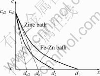
Fig.4 Change of effective boundary layer as function of concentration of nickel at solid/liquid interface
4 Conclusions
1) When immersing solid Ni in liquid Zn saturated with Fe, the intermetallic compound layers consisted of γ and δ phases exist at the Ni/Zn interface, of which the morphology and phases are the same as those in liquid pure zinc. However, it is different that some Γ2 phase particles are formed in the liquid near the solid/liquid interface due to the existence of saturated iron. These Γ2 particles can be easy to heterogeneously nucleate on ζ particles and grow fast.
2) The dissolution mechanism of solid nickel in liquid zinc saturated with Fe is significantly different from that in liquid pure zinc and governed by diffusion of nickel atom across a concentration boundary layer in the liquid. The formation of Γ2 phase makes the effective thickness of concentration boundary layer near the solid/liquid interface decrease and the dissolution rate of nickel in liquid zinc accelerate.
References
[1] GIORGI M L, DURIGHELLO P, NICOLLE R, GUILLOT J B. Dissolution kinetics of iron in liquid zinc [J]. J Materials Science, 2004, 39(18): 5803-5808.
[2] DYBKOV V I, BARMAK K, LENGAUER W, GAS P. Interfacial reaction of solid nickel with liquid bismuth and Bi-base alloys [J]. J Alloy Compounds, 2005, 389(1/2): 61-74.
[3] SNUGOVSKY L, RUGGIERO M A, PEROVIC D D, RUTTER J W. Experiments on interaction of liquid tin with solid copper [J]. Materials Science and Technology, 2003, 19(7): 866-874.
[4] KONG G, LU J T, XU Q Y. Refinement of intermetallic compounds of Zn-2Ni alloy [J]. The Chinese Journal of Nonferrous Metals, 2006, 16(4): 657-662. (in Chinese)
[5] ALLEN C J, KOLISNYK P S. Nickel zinc direct alloying technology [C]//Proc 2nd Asian-Pacific General Galva Conf. Kobe: JGA, 1993: 269-277.
[6] CHEN Z W, KENNON N F, SEE J B, BARTER M A. Technigalva and other developments in batch hot-dip galvanizing [J]. JOM, 1992, 44(1): 22-66.
[7] LU J T, CHE C S, KONG G, FUMIO N. Influence of silicon on the α-Fe/Γ interface of hot-dip galvanized steels [J]. Surface and Coating Technology, 2006, 200(18/19): 5277-5281.
[8] YOSHINORI W, KAZUO U, MASAHIRO Y, et al. Effect of electroless nickel plating on reaction between silicon-containing steels and molten zinc [J]. J Iron and Steel Institute of Japan, 1999, 85(9): 46-52.
[9] KONG G, LU J T, XU Q Y. Dissolution mechanism of solid nickel in liquid zinc [J]. The Chinese Journal of Nonferrous Metals, 2006, 16(2): 268-272. (in Chinese)
[10] SU X P, TANG N Y, TOGURI J M. Thermodynamic evaluation of the Fe-Zn system [J]. J Alloys and Compounds, 2001, 325(1/2): 129- 136.
[11] MARDER A R. The metallurgy of zinc-coated steel [J]. Progress in Mater Science, 2000, 45(13): 191-271.
[12] WANG W J, LIN J P, WANG Y L, ZHANG G Y, CHENG L. Isothermal corrosion (γ prime+γ) Ni3Al alloy in liquid zinc [J]. Trans Nonferrous Met Soc China, 2006, 16(z2): 206-210.
[13] LANGGERG D E, NILMANI M. Production of nickel-zinc alloys by powder injection [J]. Metall Mater Trans, 1996, 27B(6): 780-787.
[14] TANG N Y, SU X P, TOGURI J M. Experimental study and thermodynamic assessment of the Zn-Fe-Ni system [J]. Calphad, 2001, 25(2): 267-277.
[15] VASSILEV G P, ACEBO T G, TEDENAC J C. Thermodynamic optimization of the Ni-Zn system [J]. J Phase Equilibria, 2000, 21(3): 287-300.
[16] DYBKOV V I. Regularities of reactive diffusion and phase formation in Ni-Bi, Ni-Zn, and Co-Zn binary systems [J]. Powder Metallurgy and Metal Ceramics, 2001, 40(7/8): 428-431.
[17] NASH P, PAN Y Y. The Ni-Zn system [J]. Bulletin of Alloy Phase Diagrams, 1987, 8(5): 422-429.
[18] ISHIDA T. Rate of dissolution of solid nickel in liquid tin under static conditions [J]. Metallurgy Transactions, 1986, 17B(2): 281-289.
[19] CRITCHLEY J K, DENTON S. The crystal structure of δ-Ni-Zn [J]. Journal of Institute Metals, 1971, 99(1): 26-99.
[20] CRAWLEY A F. Densities and viscosities of some liquid alloys of zinc and cadmium [J]. International Metal Reveiw, 1974, 19(1): 32- 48.
[21] DELL S ?, CHALES J, VLOT M, RANDLE V. Modelling of iron dissolution during hot dip galvanizing of strip steel [J]. Materials Science and Technology, 2004, 20(2): 251-256.
[22] ROY A K, CHHABRA R P. Prediction of solute diffusion coefficients in liquid metals [J]. Metallurgy Transactions, 1988, 19A(2): 273-279.
[23] SHIAH S W, YANG B C, CHEUNG F B, SHIH Y C. Natural convection mass transfer along a dissolution boundary layer in an isothermal binary metallic system [J]. Inter Journal of Heat and Mass Transfer, 1998, 41(23): 3759-3769.
[24] DYBKOV V I. Interaction of iron-nickel alloys with liquid aluminium [J]. J Mater Sci, 1993, 28(23): 6371-6380.
Corresponding author: KONG Gang; Tel: +86-20-85511540; E-mail: konggang@scut.edu.cn
(Edited by LI Xiang-qun)

