Optimization of process parameters for producing AA6061/SiC nanocomposites by friction stir processing
来源期刊:中国有色金属学报(英文版)2012年第5期
论文作者:M. SALEHI M. SAADATMAND J. AGHAZADEH MOHANDESI
文章页码:1055 - 1063
关键词:AA6061/SiC纳米复合材料;Taguchi参数设计方法;搅拌磨擦加工技术;方差分析
Key words:AA6061/SiC nanocomposites; Taguchi parametric design approach; friction stir processing; analysis of variance
摘 要:采用搅拌摩擦技术制备AA6061/SiC纳米复合材料,并用实验设计方法来确定影响AA6061/SiC复合材料极限拉伸强度的重要因素,包括4种因素,即旋转速度、横向速度、切削深度、搅拌头形状。运用Taguchi方法, 得到优化的工艺参数。方差分析表明,旋转速度是最主要的影响因素。统计分析结果表明,采用带螺纹的搅拌头得到的复合材料的极限拉伸强度比采用方型搅拌头的高。搅拌头的旋转速度越快、横向速度越慢,则复合材料的极限拉伸强度越高。
Abstract:
Design of experiment (DOE) was applied to determining the most important factors which influence ultimate tensile strength (UTS) of AA6061/SiC nanocomposites produced by friction stir processing (FSP). Effect of four factors, including rotational speed, transverse speed, tool penetration depth and pin profile, on UTS, was investigated. By Taguchi method, the optimum of process parameters were determined. Analysis of variance shows that the rotational speed is the most influential parameter. The statistical results depict that UTS for threaded pin is larger than that for square pin. Also, the higher the rotational speed and the lower the transverse speed, the higher the UTS.

![]()

Trans. Nonferrous Met. Soc. China 22(2012) 1055-1063
M. SALEHI, M. SAADATMAND, J. AGHAZADEH MOHANDESI
Department of Mining and Metallurgical Engineering, Amir Kabir University of Technology,Hafez Ave, Tehran, Iran
Received 7 September 2011; accepted 15 December 2011
Abstract: Design of experiment (DOE) was applied to determining the most important factors which influence ultimate tensile strength (UTS) of AA6061/SiC nanocomposites produced by friction stir processing (FSP). Effect of four factors, including rotational speed, transverse speed, tool penetration depth and pin profile, on UTS, was investigated. By Taguchi method, the optimum of process parameters were determined. Analysis of variance shows that the rotational speed is the most influential parameter. The statistical results depict that UTS for threaded pin is larger than that for square pin. Also, the higher the rotational speed and the lower the transverse speed, the higher the UTS.
Key words: AA6061/SiC nanocomposites; Taguchi parametric design approach; friction stir processing; analysis of variance
1 Introduction
Aluminum alloys are very promising for structural applications in aerospace, military, and transportation industries due to their low density, high specific strength and resistance to corrosion, and specially regarding high energy cost. In comparison with the unreinforced aluminum alloys, aluminum matrix composites reinforced with ceramic phases exhibit higher strength and stiffness, improved tribological characteristics, and increased resistance to creep and fatigue. The particulate composites with large ceramic particles are prone to cracking during mechanical loading, leading to premature failure and low ductility of the composites [1]. The mechanical properties of metal matrix composites (MMCs) can be further enhanced by decreasing the sizes of ceramic particulates and/or matrix grains from micrometer to nanometer level .MA et al [2] showed that the tensile strength of the 1% (volume fraction) Si3N4 (15 nm)/Al composite is comparable to that of the 15% SiCp (3.5 μm)/Al composite, and that yield strength of the former is much higher than that of the latter. Also, KANG and CHAN [3] showed that after the addition of a small amount (~1%) of nano-particulate in the Al, the hardness of the metal was comparable to that of a 10% SiCp (13 μm)/Al. Use of nanoparticles to reinforce metallic materials has inspired considerable research interest in recent years because of the potential development of novel composites with unique mechanical and physical properties.
To achieve desired mechanical properties of nano-composites, reinforcing nanoparticles must be distributed uniformly within metal matrix of the composites. However, homogeneous dispersion of ceramic nanoparticles in metals is difficult to achieve. Metal matrix nano composites (MMNCs) can be prepared by incorporating ex-situ ceramic nanoparticles into matrix via either powder metallurgy (PM) or liquid metallurgy route. For example, YANG et al [4] studied on bulk aluminum matrix nano-composite fabricated by ultrasonic dispersion of nano-sized SiC particles in molten aluminum alloy and reported the partial oxidation of SiC nanoparticles. KHADEM et al [5] and GU [6] successfully incorporated nanoscale SiC particulates in pure Al matrix using the mechanical milling process. For MMNCs prepared by liquid metallurgy route, the nanoparticles tend to agglomerate into coarse clusters and it is hard to avoid the interfacial reaction between reinforcement and metal-matrix and the formation of some detrimental phases. In PM technique consisting of conventional pressing and sintering, the mixing of nano-sized ceramic particles is lengthy, expensive, and energy consuming. Also, the nano-sized reinforcements always prevent composites from densification.
Currently, FSP has been used for producing Mg [7] and Al based nano-composites [8-10]. In contrast to PM and liquid metallurgy, the FSP provides the following advantages: 1) a solid state process to prevent problems associated with liquid metallurgy; 2) severe plastic deformation to promote mixing and refining of constituent phases in the material; and 3) hot consolidation to form fully dense solid. FSP was developed by MISHRA et al [11] based on the concept of friction stir welding (FSW). The basic concept of FSP is remarkably simple. A rotating tool with pin and shoulder is inserted in a single piece of material for microstructural modification and traversed along the desired line to cover the region of interest. Friction between the tool and workpieces results in localized heating that softens and plasticizes the workpiece. A volume of processed material is produced by movement of materials from the front of the pin to the back of the pin [11]. During this process, the material undergoes intense plastic deformation, which results in significant grain refinement [12].
Several researchers [11,13-16] reported that the processing parameters, namely, tool pin profile, tool rotation rate, traveling speed, and tool penetration depth, exhibited significant effects on the properties of MMCs. In order to study the effect of FSP process parameters, all workers follow the traditional experimental techniques, i.e., varying one parameter at a time while keeping others constant [13-19]. For example, AZIZIEH et al [14] studied the effect of rotation speed and probe profile on microstructure and hardness of AZ31/Al2O3 nano- composites. MAHMOUD et al [16] and KURT et al [15] investigated the effect of rotation speed and travelling speed on formation and obtained properties of Al/SiC composites. This conventional parametric design of experiment approach is time-consuming and calls for enormous resources. Hence efforts must be placed on developing effective, analytical methods to study FSP process. To study the effect of process parameters by limiting the number of experiments, using statistical methods, such as the Taguchi design of experiment approach, could be very useful [20].
In the present work, the DOE method was employed to investigate the effect of process parameters on the properties of MMNCs produced via FSP. In respect that, the Taguchi L16 method was adopted to analyze the effect of each processing parameters (i.e., pin profile, rotational speed, transverse speed, and tool penetration depth) for optimum tensile strength of AA6061/SiC nano-composites(ASNCs) produced by one FSP pass.
2 Experimental
2.1 Materials and methods
Commercially available nano-sized SiC powders (99.5% purity and 50 nm average particle size) and 6061 Al alloy in the form of rolled plate of 8 mm thickness were used as reinforcement particulates and substrate, respectively. The chemical composition of the base metal is presented in Table 1. The plates were cut into rectangular pieces of 220 mm×50 mm×8 mm.
Table 1 Chemical composition of 6061 alloy (mass fraction, %)

Non-consumable tools made of H-13 steel with two different pin profiles (threaded and square) were used to perform the FSP, while the shoulder diameter was 20 mm and the probe length and diameter were 6 mm and 7.8 mm, respectively. The shoulder tilt angle was fixed at 3°. The reinforcement powder was packed in a groove of 1 mm in width and 5.9 mm in depth cut from the 6061Al plate. In order to prevent sputtering of SiC powder and its ejection from groove during the process, groove’s gap initially was closed by means of a tool that only had shoulder and no pin. Single pass FSP was used to fabricate the ASNCs. After finalizing FSP, the ASNCs were machined to the required dimensions to prepare tensile specimens. An ASTM E8 guideline was followed for preparing the test specimens. Tensile tests were carried out using an Instron machine at a strain rate of 5×10⁻³ s-1. Figure 1 shows position and dimensions of tensile specimen. Cross-sectional samples for microstructural examination were prepared following standard metallographic procedures and examined by an Olympus optical microscope, Phillips scanning electron microscope (SEM) and atomic force microscope (AFM) without etching.

Fig. 1 Position and dimensions of tensile specimen according to ASTM E8 (All dimensions are in mm)
2.2 Experimental design for Taguchi method
It has been clearly shown in Refs. [11,13-20] that FSP process parameters, such as pin profiles, rotational speed, transverse speed and tool penetration depth, significantly influence the process and play a major role in characteristic and mechanical properties of the studied material. Several investigations used square and threaded pin profiles [16,20-22], 800-1600 r/min for rotational speed [9,10,17,21,23], 40-160 mm/min for transverse speed [8-10,17,21,23] and 0.12-0.3 mm for tool penetration depth [13, 15].
Three four-level parameters (rotational speed, transverse speed, and tool penetration depth) and one two-level parameter (pin profile) were positioned as mixed L16 (26×43) orthogonal array design (Table 2). Tool penetration depth was considered from the first contact point of the tool shoulder and work piece surface. It should be mentioned that only the main factor effects are taken into consideration and not the interactions.
A total of 16 runs were conducted, using the combination of levels for each process parameters. As compared to conventional full factorial experiment design, by using Taguchi method 112 FSP runs can be eliminated, resulting in great advantages in terms of time and cost. The analyses were carried out using MINITAB15 statistical software.
Table 2 Basic Taguchi L16 orthogonal array

3 Results and discussion
3.1 Statistical analysis
In order to optimize FSP process parameters, the tensile strength was analyzed. To assess the influence of factors on the response, the means and S/N ratios for each control factor can be calculated. In this study, the S/N ratio was chosen according to the criterion of the larger-the-better, in order to maximize the response. The S/N ratio is calculated using the larger-the-better criterion and is given by [20]:
![]() (1)
(1)
where y is the observed data and n is the number of observations. The obtained tensile strengths were converted into mean and S/N ratio. The experimental results and calculated mean and S/N ratio values are tabulated in Table 3. The calculated mean response and S/N ratio of tensile strength for each parameter for all levels are listed in Table 4.
Table 3 Experimental results and calculated mean and S/N ratio

Response optimization helps to identify the combination of input variable settings that jointly optimize a single response or a set of responses. Based on the highest values of the S/N ratio and mean levels (Table 4), it can be inferred that higher tensile strength could be obtained when the rotational speed and tool penetration depth are high, transverse speed is low and pin profile is threaded. The optimum level setting was obtained at 1600 r/min of rotational speed (level 4), 40 mm/min of transverse speed (level 1), 0.30 mm of tool penetration depth (level 4), and threaded pin profile (level 2).
After the optimum condition was determined, the optimum performance of the response under the optimum condition was predicted. The optimum value of the response characteristic is estimated as follows [20]:
α![]()
![]() (2)
(2)
where σ is the tensile strength; T is the overall mean of tensile strength; ![]() is the average tensile strength at the fourth level of rotational speed (1600 r/min);
is the average tensile strength at the fourth level of rotational speed (1600 r/min); ![]() is the average tensile strength at the first level of transverse speed (40 mm/min);
is the average tensile strength at the first level of transverse speed (40 mm/min); ![]() is the average tensile strength at the fourth level of tool penetration depth (0.3 mm);
is the average tensile strength at the fourth level of tool penetration depth (0.3 mm); ![]() is the average tensile strength at the second level of pin profile (threaded). Substituting the values of various terms in Eq. (2) gives:
is the average tensile strength at the second level of pin profile (threaded). Substituting the values of various terms in Eq. (2) gives:
σ=99.42+20.54+20.88+5.64+8.73=155.21 MPa
The final step in the DOE approach is to conduct confirmation experiments for the optimal parameters determined. As explained above, the optimum design was determined to be ![]()
![]()
![]()
![]() . It must be noted that the above combination of factor levels is among the sixteen combinations tested for the experiment and the average tensile strength of ASNCs was found to be 153.7 MPa. There is a good agreement between the predicted (155.21 MPa) and actual (153.7 MPa) values.
. It must be noted that the above combination of factor levels is among the sixteen combinations tested for the experiment and the average tensile strength of ASNCs was found to be 153.7 MPa. There is a good agreement between the predicted (155.21 MPa) and actual (153.7 MPa) values.
The main purpose of the ANOVA is the application of a statistical method to identify the effect of individual factors on the process response. Results from ANOVA can determine very clearly the impact of each factor on tensile strength. The ANOVA table for both mean and S/N ratio is calculated and listed in Tables 5 and 6. In addition, the F test was used to determine which process parameters have a significant effect on tensile strength. Larger F value indicates that variation of the process parameter makes a considerable change on the performance characteristics. The results of ANOVA indicate that the rotational speed has the highest effect on the strength followed by the transverse speed, pin profile, and tool penetration depth, respectively. Furthermore, the F test justifies that rotational speed has statistically significant influence on the strength.
Table 4 Main effects of process parameters (means and S/N ratio)
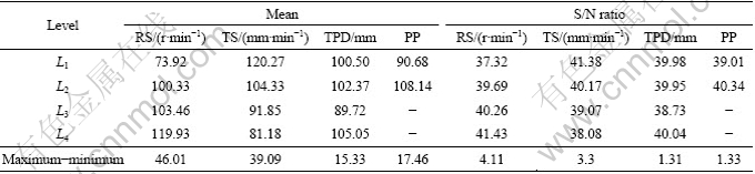
Table 5 Analysis of variance for means

Table 6 Analysis of variance for S/N ratio

The Taguchi experimental method could not judge the effect of individual parameters on the entire process, thus the percentage of contribution using ANOVA is used to compensate for this effect. Percent contribution indicates the relative power of a factor to reduce variation. For a factor with a high percent contribution, a small variation will have a great influence on the performance. The percentage of contribution (fi) is a function of the sum of squares for each significant item and can be calculated as [24]:
![]() (3)
(3)
where fi is the ith factor; ![]() is the pure sum of squares for fi; and
is the pure sum of squares for fi; and ![]() is the total mean of sequential sum of squares. Based on the results presented in Tables 5 and 6, the rotational speed is found to be the most influential process parameter with 43.70% contribution followed by transverse speed (33.79%), pin profile (11.22%), and tool penetration depth (4.21%), respectively, as this apportionment shown in Fig. 2. MAHMOUD et al [16] studied the formation of SiC particle reinforced composite on aluminium surface by FSP and they found that the rotational speed was the main parameter affecting the distribution of the SiC particles.
is the total mean of sequential sum of squares. Based on the results presented in Tables 5 and 6, the rotational speed is found to be the most influential process parameter with 43.70% contribution followed by transverse speed (33.79%), pin profile (11.22%), and tool penetration depth (4.21%), respectively, as this apportionment shown in Fig. 2. MAHMOUD et al [16] studied the formation of SiC particle reinforced composite on aluminium surface by FSP and they found that the rotational speed was the main parameter affecting the distribution of the SiC particles.

Fig. 2 Contribution of process parameters (means)
3.2 Microstructure and tensile strength
The results of tensile tests conducted on ASNCs under various conditions of process parameters are listed in Table 3. For a given process parameter combination, significant differences, ranging from 66.05 MPa to 153.7 MPa, were observed in UTS, indicating that the process parameters have a strong effect (more than 2.3 times) on the strength. Among the 16 samples examined, samples 3 (800 r/min, 125 mm/min, 0.24 mm, and threaded) and 13 (1600 r/min, 40 mm/min, 0.30 mm, and threaded) showed the lowest (66.05 MPa) and highest (153.7 MPa) UTS, respectively. It is worthy to note that the tensile strength of sample 13 is higher than that for the as-rolled AA 6061(Annealed) alloy (125 MPa) [25]. This might be attributed to the strengthening mechanisms involving in the friction stir processed specimens such as Orowan [10, 26], enhanced dislocation density in matrix induced by the thermal mismatch between the matrix and the reinforcement particles [27], and grain refinement [10, 26, 28]. Similar results were observed by HU et al [29] and BAURI et al [28].
Macroscopic appearances of samples 3 and 13 are shown in Fig. 3. There are no voids and cracks in the cross section of both samples, indicating that the selected combination of process variables according to the previous work [13] is within the accepted range. It is apparent that the powder distribution in the stir zone of sample 13 is more wide and uniform than that for sample 3. Although in both samples, some unmixed SiC powders were observed inside the FSP processed zone, the amount of unmixed powders is lower in sample 13 seemingly due to application of one process pass, similar to the results reported by YANG et al [19]. Microscopic examinations (Fig. 4) reveal that the process variables have significant effects on the formation of composite zone. For sample 13 (Fig. 4(a)), the material flow and the onion ring [30] could be easily observed by the SiC dispersion. There are a few regions which include the aggregated nano-sized particles; however, a good dispersion of 4% SiC particles, is confirmed by SEM (Fig. 5(a)) and AFM micrographs (Fig. 5(b)). For the sample 3 (Fig. 4(b)), the onion ring is not observed and the stir zone includes bands of unmixed powder, non-reinforced matrix (base alloy), and reinforced matrix. The better microstructure characteristic of sample 13 might be attributed to more vigorous stirring action during the FSP due to better combinations of process parameters. In comparison to sample 3, sample 13 has experienced more tool rotational speed, less transverse speed, and more penetration depth during FSP, giving more time to stirring action, although the effect of the third parameters is less than the other two (i.e., 4.21% compare to 43.70% and 33.79% according to ANOVA, Table 6). Close relation between the formation of onion ring (composite zone) and the process parameters in the fullerene/A5083 composites fabricated by FSP was reported by MORUISADA et al [9]. Although Taguchi method predicted the optimized condition for producing ASNCs (section 3.1), observing some unmixed powders (Fig. 3(a)) together with aggregated particles in the stir zone (Fig. 4(a)) concludes that one pass FSP is insufficient. These results are in accordance to the pervious results [19,31].

Fig. 3 Optical macroscopic appearances of cross sections: (a) Sample 13; (b) Sample 3

Fig. 4 Optical microstructures of center of stir zone: (a) Sample 13; (b) Sample 3
It is clear from Figs. 6(a) and 6(b), as the rotational speed increases, the tensile strength will increase and decrease with increase in transverse speed. Other researchers have made similar observations [8,9,15,23,32]. The dispersion morphology could be controlled by the rotational speed/traverse speed (RS/TS) ratio. The higher the RS/TS ratio, the higher the heat input, inflicting more softening in the process zone that results in an easier stirring action of the tool pin. More intense stirring action causes better particle distribution and smaller particle cluster size (Figs. 3 and 4), which results in superior obtained properties. Consequently, higher tensile strength of the ASNCs fabricated with higher RS or lower TS is justified.
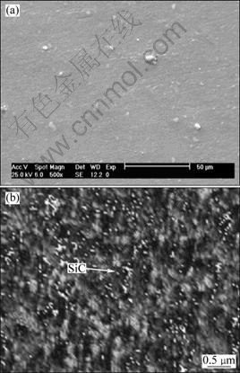
Fig. 5 SEM (a) and AFM (b) images of ASNCs (sample 13) showing a good dispersion of SiC in matrix
The ASNCs fabricated using the threaded pin profile has higher tensile strength compared to that made using square pin profile (Fig. 6(c)). It has been shown that a composite zone can be formed in the process zone during the FSP [9,16,19]. The most important part of the tool is the pin, which plays a crucial role in material flow and mixing [33-36] especially on the lower two thirds of the stir zone [37]. In polygonal profiled pin, the pin bottom area of the tool is smaller than that of the cylindrical pin. Additionally, the frictional area between the pin side and the stirring material is limited to near sharp edges, which is very smaller than that of the column probe. Since larger frictional area will generate larger amount of friction heat, the friction heat generated by the polygonal probe should be smaller than that by the cylindrical pins. Therefore, the bottom surface temperature is always lower than the others, which produces an unsuitable viscosity in the process zone matrix for dispersion of the particles due to lack of heat in the stir zone. FUJII et al [38] reported that under the same process parameter on the bottom surface, the peak temperature for the triangular prism tool is lower than that for the cylindrical pin tool on FSW of 1050-H24 aluminium alloy. On the other hand, the screw thread on the pin drives the vertical material flow in the stir zone; the material is pushed downward near the pin by the thread washes and moves upward to the top of the stir zone to complete the circulation. This circulation probably helps the mixing of material in the vertical direction [30,39,40]. Enhanced particle distribution by using a threaded pin in AZ31/Al2O3 nano-composites fabricated by FSP was also reported by AZIZIEH et al [14].

Fig. 6 Effect of process variables on tensile strength: (a) Mean tensile strength vs rotational speed; (b) Mean tensile strength vs transverse speed; (c) Mean tensile strength vs pin profile
Finally, based on the present ANOVA results (Tables 5 and 6), it may be concluded that, the contribution of the tool penetration depth, within the factor range selected in this study, is insignificant (i.e., 4.21%) in comparison with three other variables (i.e., rotational speed of 43.70%, transverse speed of 33.79%, and pin profile of 11.22%), where the error of ANOVA in this study is 7.08%.
5 Conclusions
1) The L16 Taguchi orthogonal designed experiments of FSP on ASNCs were successfully conducted and the process parameters have a critical role in the quality of the obtained composites.
2) The FSP process parameters were optimized to maximize the tensile strength of ASNCs. The optimum condition of the rotational speed, transverse speed, tool penetration depth, and pin profile were found to be 1600 r/min, 40 mm/min, 0.30 mm and threaded type, respectively.
3) The rotational speed is found to be the most influential process parameter with 43.70% contribution followed by transverse speed (33.79%), pin profile (11.22%), and tool penetration depth (4.21%), respectively.
4) The prediction of the Taguchi design approach was in good agreement with the experimental result.
5) ASNCs with a higher tensile strength were obtained for threaded pin at a higher rotational speed and tool penetration depth and lower transverse speed.
Acknowledgement
The authors would like to thank Mr. A. K. SAGHAFI for his helpful comments, Mechanical Engineering Department of Amirkabir University of Technology and Iran Nanotechnology Initiative for experimental and financial supports.
References
[1] TJONG S C. Novel nanoparticle-reinforced metal matrix composites with enhanced mechanical properties [J]. Advanced Engineering Materials, 2007, 9(8): 639-652.
[2] MA Z Y, LI Y L, LIANG Y, ZHENG F, BI J, TJONG S C. Nanometric Si3N4 particulate-reinforced aluminum composite [J]. Materials Science and Engineering A, 1996, 219(1-2): 229-231.
[3] KANG Y C, CHAN S L. Tensile properties of nanometric Al2O3 particulate-reinforced aluminum matrix composites [J]. Materials Chemistry and Physics, 2004, 85(2-3): 438-443.
[4] YANG Y, LAN J, LI X. Study on bulk aluminum matrix nano-composite fabricated by ultrasonic dispersion of nano-sized SiC particles in molten aluminum alloy [J]. Materials Science and Engineering A , 2004, 380(1-2): 378-383.
[5] KHADEM S A, NATEGH S, YOOZBASHIZADEH H. Structural and morphological evaluation of Al-5vol.%SiC nanocomposite powder produced by mechanical milling [J]. Journal of Alloys and Compounds, 2011, 509(5): 2221-2226.
[6] GU Wan-li. Bulk Al/SiC nanocomposite prepared by ball milling and hot pressing method [J]. Transactions of Nonferrous Metals Society of China, 2006, 16(1): 398-401.
[7] LEE C J, HUANG J C, HSIEH P J. Mg based nano-composites fabricated by friction stir processing [J]. Scripta Materialia, 2006, 54(7): 1415-1420.
[8] LIM D K, SHIBAYANAGI T, GERLICH A P. Synthesis of multi-walled CNT reinforced aluminium alloy composite via friction stir processing [J]. Materials Science and Engineering A, 2009, 507(1-2): 194-199.
[9] MORUISADA Y, FUJII H, NAGAOKA T, NOGI K, FUKUSUMI M. Fullerene/A5083 composites fabricated by material flow during friction stir processing [J]. Composites A, 2007, 38(10): 2097-2101.
[10] SHAFIEI-ZARGANI A, KASHANI-BOZORG S F, ZAREI- HANZAKI A. Microstructures and mechanical properties of Al/Al2O3 surface nano-composite layer produced by friction stir processing [J]. Materials Science and Engineering A, 2009, 500(1-2): 84-91.
[11] MISHRA R S, MA Z Y, CHARIT I. Friction stir processing: A novel technique for fabrication of surface composite [J]. Materials Science and Engineering A, 2003, 341(1-2): 307-310.
[12] MISHRA R S, MAHONEY M W, MCFADDEN S X, MARA N A, MUKHERJEE A K. High strain rate superplasticity in a friction stir processed 7075 Al alloy [J]. Scripta Materialia, 2000, 42(2): 163-168.
[13] ASADI P, FARAJI G, BESHARATI M K. Producing of AZ91/SiC composite by friction stir processing (FSP) [J]. International Journal of Advanced Manufacturing Technology, 2010, 51(1-4): 247-260.
[14] AZIZIEH M, KOKABI A H, ABACHI P. Effect of rotational speed and probe profile on microstructure and hardness of AZ31/Al2O3 nanocomposites fabricated by friction stir processing [J]. Materials and Design, 2011, 32(4): 2034-2041.
[15] KURT A, UYGUR I, CETE E. Surface modification of aluminium by friction stir processing [J]. Journal of Materials Processing Technology, 2011, 211(3): 313-317.
[16] MAHMOUD E R I, IKEUCHI K, TAKAHASHI M. Fabrication of SiC particle reinforced composite on aluminium surface by friction stir processing [J]. Science and Technology of Welding and Joining, 2008, 13(7): 607-618.
[17] BARMOUZ M, BESHARATI GIVI M K, SEYFI J. On the role of processing parameters in producing Cu/SiC metal matrix composites via friction stir processing: Investigating microstructure, microhardness, wear and tensile behavior [J]. Materials Characterization, 2011, 62(1): 108-117.
[18] RAAFT M, MAHMOUD T S, ZAKARIA H M, KHALIFA T A. Microstructural, mechanical and wear behavior of A390/graphite and A390/Al2O3 surface composites fabricated using FSP [J]. Materials Science and Engineering A, 2011, 528(18): 5741-5746.
[19] YANG M, XU C, WU C, LIN K, CHAO Y J, AN L. Fabrication of AA6061/Al2O3 nano ceramic particle reinforced composite coating by using friction stir processing [J]. Journal of Material Science, 2010, 45(16): 4431-4438.
[20] MAHMOUD E R I, TAKAHASHI M, SHIBAYANAGI T, IKEUCHI K. Effect of friction stir processing tool probe on fabrication of SiC particle reinforced composite on aluminium surface [J]. Science and Technology of Welding and Joining, 2009, 14(5): 713-725.
[21] WANG W, SHI Q, LIU P, LI H, LI T. A novel way to produce bulk SiCp reinforced aluminum metal matrix composites by friction stir processing [J]. Journal of Materials Processing Technology, 2009, 209(4): 2099-2103.
[22] ZAHMATKESH B, ENAYATI M H. A novel approach for development of surface nanocomposite by friction stir processing [J]. Materials Science and Engineering A, 2010, 527(24-25): 6734-6740.
[23] MORISADA Y, FUJII H, NAGAOKA T, FUKUSUMI M. Effect of friction stir processing with SiC particles on microstructure and hardness of AZ31 [J]. Materials Science and Engineering A, 2006, 433(1-2): 50-54.
[24] ROY R. A primer on the taguchi method [M]. United States of America: Society of Manufacturing Engineers, 1990.
[25] American Society of Metals Hand Book. Metals hand book: Vol. 2 [M]. 10th ed. USA: ASM International, 1990.
[26] CHEN C F, KAO P W, CHANG L W, HO N J. Effect of processing parameters on microstructure and mechanical properties of an Al-Al11Ce3-Al2O3 in-situ composite produced by friction stir processing [J]. Metallurgical and Materials Transactions A, 2010, 41(2): 513-522.
[27] LEE I S, HSU C J, CHEN C F, HO N J, KAO P W. Particle-reinforced aluminum matrix composites produced from powder mixtures via friction stir processing [J]. Composites Science and Technology, 2011, 71(5): 693-698.
[28] BAURI R, YADAV D, SUHAS G. Effect of friction stir processing (FSP) on microstructure and properties of Al-TiC in situ composite [J]. Materials Science and Engineering A, 2011, 528(13-14): 4732-4739.
[29] HU C M, LAI C M, DU X H, HO N J, HUANG J C. Enhanced tensile plasticity in ultrafine-grained metallic composite fabricated by friction stir process [J]. Scripta Materialia, 2008, 59(11): 1163-1166.
[30] KRISHNAN K N. On the formation of onion rings in friction stir welds [J]. Materials Science and Engineering A, 2002, 327(2): 246-251.
[31] ASADI P, BESHARATI GIVI M K, ABRINIA K, TAHERISHARGH M, SALEKROSTAM R. Effects of SiC particle size and process parameters on the microstructure and hardness of AZ91/SiC composite layer fabricated by FSP [J]. Journal of Materials Engineering and Performance, 2011, 20(9): 1554-1562.
[32] FARAJI G, ASADI P. Characterization of AZ91/alumina nanocomposite produced by FSP [J]. Materials Science and Engineering A, 2011, 528(6): 2431-2440.
[33] BOZ M, KURT A. The influence of stirrer geometry on bonding and mechanical properties in friction stir welding process [J]. Materials and Design, 2004, 25(4): 343-347.
[34] ELANGOVAN K, BALASUBRAMANIAN V. Influences of tool pin profile and welding speed on the formation of friction stir processing zone in AA2219 aluminium alloy [J]. Journal of Materials Processing Technology, 2008, 200(1-3): 163-175.
[35] KULEKCI M K, SIK A, KALUC E. Effects of tool rotation and pin diameter on fatigue properties of friction stir welded lap joints [J]. International Journal of Advanced Manufacturing Technology, 2008, 36(9-10): 877-882.
[36] ZHAO Y, LIN S, WU L, QU F. The influence of pin geometry on bonding and mechanical properties in friction stir weld 2014 Al alloy [J]. Materials Letters, 2005, 59(23): 2948-2952.
[37] MUTKUKUMARAN S, MUKHEJEE S K. Multi-layered metal flow and formation of onion rings in friction stir welds [J]. International Journal of Advanced Manufacturing Technology, 2008, 38(1-2): 68-73.
[38] FUJII H, CUI L, MAEDA M, NOGI K. Effect of tool shape on mechanical properties and microstructure of friction stir welded aluminum alloys [J]. Materials Science and Engineering A, 2006, 419(1-2): 25-31.
[39] CHEN Z W, CUI S. On the forming mechanism of banded structures in aluminium alloy friction stir welds[J]. Scripta Materialia, 2008, 58(5): 417-420.
[40] GUERRAA M, SCHMIDTA C, MCCLUREA J C, MURRA L E, NUNES A C. Flow patterns during friction stir welding [J]. Materials Characterization, 2003, 49(2): 95-101.
M. SALEHI, M. SAADATMAND, J. AGHAZADEH MOHANDESI
Department of Mining and Metallurgical Engineering, Amir Kabir University of Technology, Hafez Ave, Tehran, Iran
摘 要:采用搅拌摩擦技术制备AA6061/SiC纳米复合材料,并用实验设计方法来确定影响AA6061/SiC复合材料极限拉伸强度的重要因素,包括4种因素,即旋转速度、横向速度、切削深度、搅拌头形状。运用Taguchi方法, 得到优化的工艺参数。方差分析表明,旋转速度是最主要的影响因素。统计分析结果表明,采用带螺纹的搅拌头得到的复合材料的极限拉伸强度比采用方型搅拌头的高。搅拌头的旋转速度越快、横向速度越慢,则复合材料的极限拉伸强度越高。
关键词:AA6061/SiC纳米复合材料;Taguchi参数设计方法;搅拌磨擦加工技术;方差分析
(Edited by YANG Hua)
Corresponding author: M. SALEHI; Tel: +989123995145; Fax: +982166405846; E-mail: m_salehi@aut.ac.ir
DOI: 10.1016/S1003-6326(11)61283-1

