Trans. Nonferrous Met. Soc. China 22(2012) s207-s213
Optimization of cold forging perform tools using Pseudo Inverse Approach
Ali HALOUANI, Yu-ming LI, ABBES Boussad, Ying-qiao GUO
GRESPI/MPSE,  de Reims Champagne-Ardenne, Moulin de la Housse, BP 1039, 51687 Reims Cedex 2, France
Received 28 August 2012; accepted 25 October 2012
Abstract: A new fast method called ��Pseudo Inverse Approach�� (PIA) for the multi-stage axi-symmetrical cold forging modelling is presented. The approach is based on the knowledge of the final part shape. Some intermediate configurations are introduced and corrected by using a free surface method to consider the deformation paths without contact treatment. A new direct algorithm of plasticity is developed using the notion of equivalent stress and the tensile curve, leading to a very efficient and robust plastic integration procedure. Numerical tests show that the Pseudo Inverse Approach is very fast compared with the incremental approach. The PIA is used in an optimization procedure for the preliminary preform tool design in multi-stage cold forging processes. This optimization problem aims to minimize the equivalent plastic strain and the punch force during the forging process. The preform tool shapes are represented by B-Spline curves. The vertical positions of the control points of B-Spline are taken as design variables. The evolution of the objective functions shows the importance of the tool preform shape optimization for the forging quality and energy saving. The forging results obtained by using the PIA are compared with those obtained by the classical incremental approaches to show the efficiency and accuracy of the PIA.
Key words: cold forging process; Pseudo Inverse Approach; preform design; B-Spline; shape optimization; Pareto front
1 Introduction
Forged parts are often used for high performance and reliability applications. In a cold forging process, the initial billet is plastically deformed under a powerful tool pressure. Two or more forging stages may be required to make a complicated forging product. The achievement of high-quality products by forging process largely depends on the preform tool design. In industry, the preform design for a forging process involves expensive trials-corrections on forging tools. The actual tendency is to use the numerical simulation and optimization in order to obtain the process information and optimal forging parameters.
The classical incremental methods are widely used for the forging simulation and optimization [1-5]. Very advanced works have been done by FOURMENT et al [6,7] from CEMEF in France. The corresponding software FORGE is largely used in the forging industry. The incremental methods give good results, but they are very time consuming. The considerable calculation cost makes their application difficult to industrial optimization problems. In this context, it will be very useful to develop a fast and robust forging solver for the preform design and optimization. A new simplified approach called Pseudo Inverse Approach (PIA) has been proposed for the axi-symmetric cold forging modelling [8,9]. This approach exploits at maximum the knowledge of the final part shape. Some intermediate configurations are introduced to take into account the deformation history. A free surface method is developed to make these configurations not only kinematically but also mechanically admissible. A new algorithm of plastic integration called Direct Scalar Algorithm (DSA) [10,11] has been proposed in the PIA, which is very efficient and robust compared to the classical Return Mapping Algorithm (RMA), especially for very large strain increments.
The main objective of this work is to simulate and optimize a two-stage metal forging process using an optimization procedure combined with the PIA in order to obtain an optimal preform tool shape. The optimization target is to minimize the equivalent plastic strain variation in the final part and the punch force during the forming process. In the optimization loop, the design variables are modified to improve the objective functions, leading to an optimum tool shape. A surrogate meta-model based on the Kriging method is used to reduce the calculation time for this strongly non linear problem.
The two-stage cold forging of a wheel is taken as an example. The evolution of the objective functions is studied. The numerical results obtained by the optimization using the PIA are compared to those obtained by a classical incremental approach.
2 Outlines of PIA
In contrast to the classical incremental methods, the Inverse Approach (IA) exploits the known shape of the final part and executes the calculation from the final part to the initial billet. Two assumptions are used: the assumption of proportional loading gives an integrated constitutive law without considering the strain path; the assumption on the part-tool contact allows one to replace the tool actions by nodal forces without contact treatment. These two assumptions make the IA calculation very fast.
The calculation of the trajectories of all material points from the initial billet to the known final part is done in one step by directly comparing the initial and final configurations. A Newton�CRaphson algorithm is used to move the nodes in the initial billet in order to satisfy equilibrium in the final part. Thus, the strain and stress states are obtained.
The PIA (or multi-step inverse approach) based on the IA has been developed to improve the stress estimation by considering the deformation history and the flow theory of plasticity. The main developments in the PIA can be summarized as follows [8,9]:
1) Using the known shapes of the initial billet and the desired final part, some intermediate configurations are generated geometrically. Then, they are corrected using the given tool positions and a free surface method without contact treatment. These configurations allow a good prediction of the strain path even for very large increments.
2) The large logarithmic strain increment is calculated by using the inverse formulation between the two successive configurations. Taking the last known configuration as reference and using the logarithmic strains for very large strain increments, the inverse formulation is largely simplified.
3) At each step, the plastic integration scheme requires the strain and stress states at the previous step. A special transfer of the strain and stress fields is carried out between the two independent meshes (mesh at step n-1 on configuration Cn and mesh at step n on the same Cn).
4) An efficient method for plastic integration called ��Direct Scalar Algorithm�� based on the flow theory is developed: using the equivalent stress notion and the tensile curve, the equations in terms of unknown stress vectors are transformed into a scalar equation, and the plastic multiplier can be directly calculated without iterations. The DSA is as accurate as the classical return mapping methods, but much faster and more robust, particularly for very large strain increments.
3 Optimization problem
The main aim of the perform optimization is to find the best preform shapes in the design space relative to different optimization criteria. An optimization problem is defined by three aspects: the design variables, the constraints and the objective functions. We should also specify the lower and upper limits of the design variables.
The fast Pseudo Inverse Approach is taken as forging solver. It is combined with the NSGA-II algorithm (Elitist Non-dominated Sorting Genetic Algorithm) in the software Mode-FRONTIER4 TM [12] to minimize the objective functions.
NSGA-II algorithm appears as one of the most efficient algorithms to find the optimal Pareto set with a great variety of solutions. Based on the elitism principle, it favours the non-dominated solutions and uses a variety of explicit solutions. NSGA-II begins with a random initial population Pt of N parent individuals. At this generation t, a population Qt of N children is created from the parent population Pt using the genetic operators (selection-crossing-mutation). Then, the two populations are combined to form a new population Rt of size 2N. The search of non-dominated solutions allows one to classify the individuals of Rt into several fronts of different ranks. It is carried out as follows: every individual of Rt is compared to all other individuals according to the concept of dominance. The non-dominated individuals belong to the front of the first rank (Pareto front). In removing temporarily these individuals, the operations are repeated to find the front of second rank, etc.
Usually, a multi-objective optimization process requires a large number of forging simulations, so it is very time consuming. The use of meta-models may be complex, especially in the case of multi-objective functions. A surrogate meta-model allows to construct an approximate response surface of the multi-objective functions by using the real simulation results relative to the sampling points in the design space. In this work, the Kriging method is adopted to get the surrogate meta-model for two objective functions.
The selection of DOE points (Design of Experiments) has an important influence on the accuracy and the cost of the surrogate meta-model. The difficulty is to achieve an approximate response surface in good quality, but using the minimum simulations. In this work, the DOE is based on a random sequence method [12].
3.1 Objective functions
The optimization problem consists in minimizing the objective functions. In this work, the two principal aims are to minimize the punch force during the forging process and to optimize the metallurgical quality in the forged parts. It is important to obtain a homogeneous and small grain size distribution in order to produce a part with a high resistance to fatigue [13].
3.1.1 Minimization of equivalent plastic strain
Complex grain size evolution laws can be introduced in the simulation software, but finding the right parameters of these laws is not easy. In a simple way and from an industrial standpoint, a homogeneous distribution of the equivalent plastic strain provides a satisfactory approximated criterion. So, the following physical function is used:
 (1)
(1)
where  is the equivalent plastic strain of the element i,
  is the average equivalent plastic strain, Nelt is the number of elements, Vi is the volume of the element i, and Vt is the total volume.
3.1.2 Minimization of punch force during forging
Another aim is to find the preform shape leading to the minimal punch force:
 (2)
(2)
where  is the maximal punch force during the forming operation.
3.2 Constraints
Even though the material incompressibility is ensured par the forming solver PIA, the volume variation should be still constrained in the optimization loop:
 (3)
(3)
where  and
and  are the initial and actual volumes, and �� is a small admissible value of the volume variation.
3.3 Design variables and tool shape parameters
3.3.1 Generation of starting preform
In this work, the generation of the starting preform is carried out as follows:
1) The shape of the final forged part Cf is known. As an initial solution, the nodes at the contour of its FE mesh are mapped on the contour of the initial billet C0. A linear solution gives the positions of the other nodes (interior nodes) in the initial billet (Fig. 1).
2) Then, we create a geometrically proportional FE mesh (Fig. 2):
 (4)
(4)
3) Finally, we generate a starting preform using a B-Spline curve which fits well the proportional mesh contour except for the free surface part (Fig. 2).

Fig. 1 Node mapping from final part to initial billet
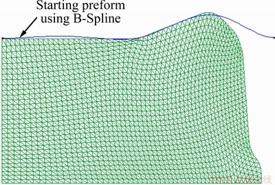
Fig. 2 Generation of starting perform shape
3.3.2 Design variables
The shape of the starting preform determined by the proportional method is then modified in the optimization loop to minimize the objectives functions. Its parametric B-Spline curve is defined as follows [14]:
 (5)
(5)
where k denotes the order of the B-Spline, n+1 is the number of control points, Ni,k are the basis polynomial functions, and pi is the position vectors of the control points. The B-Spline functions are defined by the recurrence formula of Cox Deboor [14]:

 (6)
(6)
where xi constitutes the nodal vector:
x=(x1, x2, ��, xi, ��, xn+k+1)

and the parameter u on the whole B-Spline curve varies:
0��u��n-k+2
A B-Spline curve is defined by a polygonal contour having n+1 (n+1��4) control points C1, ��, Cn+1. These control points can be active or passive. Figure 3 shows an example with seven control points, and only their vertical displacements are taken as geometrical parameters to reduce the number of design variables. C2 and C6 are the passive points having the same vertical positions than C1 and C7 in order to keep the horizontal tangents at C1 and C7, and other five control points are active points, giving only five optimization design variables.

Fig. 3 Initial and improved preforms defined by B-Spline curves using five active control points and two passive ones
4 Numerical results
The multi-stage cold forging of an axisymmetric wheel is simulated and optimized in this work. The forging process is composed of a preforming stage using a preform tool (Fig. 4) and a forging stage using the final tool given by the final desired part (Fig. 5).
The initial shape of billet is a cylinder (height of 150 mm, radius of 175 mm). The geometry of the billet, the starting preform shape and the final tools are shown in Figs. 4 and 5. The symmetric boundary conditions are imposed on the horizontal and vertical axi-symmetric axis. A quarter of the section is meshed with 1734 nodes and 3298 triangle elements. The tools are supposed rigid and modelled by analytic rigid wires. The material of the billet is the aluminium with elastic modulus E=73 GPa, Poisson ratio ��=0.42, friction coefficient ��=0.05, and Hollomon tensile curve  .
.
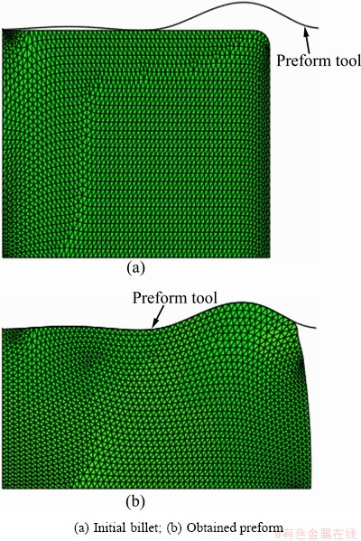
Fig. 4 Billet and tool in preforming stage
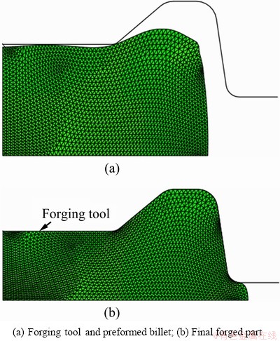
Fig. 5 Tool and forged parts in forging stage
In this work, the PIA is used between the preform and initial billet, then between the final part and preform to obtain the strains and stresses. According to our numerical tests, the results of the PIA are not sensitive to the number of steps superior to 15 steps in both stages.
In a multi-objective optimization, the concept of the best design is replaced with the concept of the non-dominant design. This set of non-dominant designs is called Pareto frontier [15]. The designer is interested in finding an optimal compromise for all objective functions considering other technical conditions.
The distribution of the initial Pareto points in the objective function plan ( and
and  ) are obtained by using 200 PIA simulations (or 200 iterations in the NSGA-II optimization loop). Using these real simulation results, we obtain the initial Pareto points (Fig. 6) for this two-objective optimization problem.
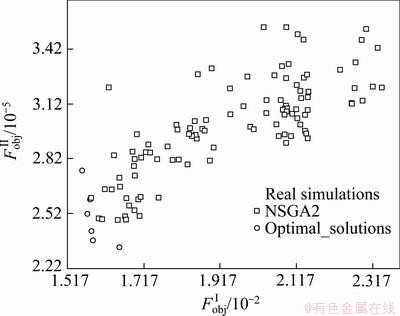
Fig. 6 Pareto points obtained by using real simulation results
Figure 7 shows the evolution of the first objective function versus the optimization iterations. It can be seen that decreases from the initial value 0.0228 to 0.015. The deformation uniformity is largely improved.
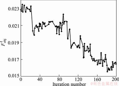
Fig. 7  versus optimization iterations
Figure 8 shows the evolution of the second objective function  versus the optimization iterations. We note also that the maximum punch force decreases from the initial value of 347.5 kN to 233.8 kN.
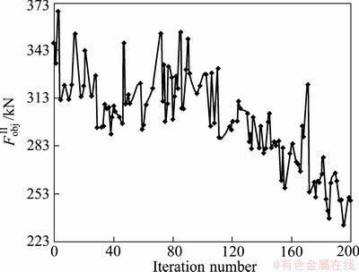
Fig. 8 versus optimization iterations
The comparison of the initial and final preform shapes (at the iterations 1 and 181) is shown in Fig. 9. Each contour is composed of two parts: the first one is determined by the contact with the preform tool, and the second is determined by the free surface method to satisfy equilibrium on the free surface (Fig. 9). Even though these contours are close to each other, the optimal preform shape enables to largely reduce the objective functions.
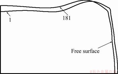
Fig. 9 Preform shapes at iterations 1 and 181
The multi-objective optimization algorithms require a large amount of calculations, so it will be very expensive to minimize the objective functions entirely using real FE simulations. The Kriging method is adopted to build the surrogate meta-model for the two objective functions. Kriging method is a nonparametric interpolation model which interpolates the responses exactly at all sampling points. Figures 10 and 11 show respectively the surrogated meta-models of the two objective functions and using Gaussian Kriging method.
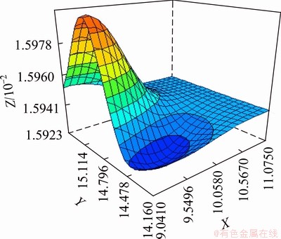
Fig. 10 Kriging Surrogate Meta-model of
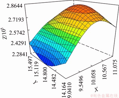
Fig. 11 Kriging Surrogate Meta-model of 
To get the optimal design values after building the Meta-model, an appropriate optimization algorithm called NSGA-II is used. The distribution of the Pareto points obtained by using NSGA-II algorithm coupled with Gaussian Kriging model is shown in Fig. 12. During the optimization, lots of new solutions are generated. The final generation contributes to more optimal values on the Pareto front giving the final optimal solutions (Fig. 12).
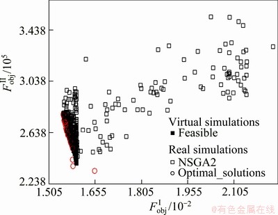
Fig. 12 Pareto front given by NSGA-II/Kriging algorithm
The validation of the forming solver PIA is done by using the software ABAQUS /Explicit. We choose the optimal solution at the iteration 181, giving the punch travels equal to 38.11 and 50.08 mm at the two stages.
Figure 13 shows the distributions of the equivalent stress obtained by the PIA and ABAQUS. We observe that the equivalent stress distributions are very close to each other. The maximum equivalent stresses are in good agreement: 66.05 MPa by PIA and 69.93 MPa by ABAQUS. The relative error is very small (5%).
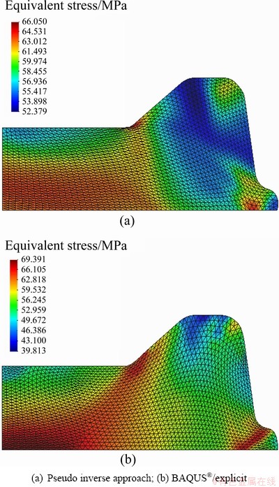
Fig. 13 Equivalent stress obtained by PIA and ABAQUS
The CPU time for the forming modelling of the wheel is also compared: ABAQUS incremental approach uses 6600 s, the PIA uses only 385 s (a ratio of 17 times). The PIA can be still much faster if the software programming is optimized.
5 Conclusions
1) A new method called ��Pseudo Inverse Approach�� (PIA) has been developed for the multi-stage cold forging process. The PIA exploits at maximum the knowledge on the final part shape, which makes the formulation very simple and the calculation very fast. The tool actions are simply represented by some external nodal forces to avoid contact treatment. In order to consider the strain path, some intermediate configurations are determined geometrically and then corrected mechanically by using a free surface method. An efficient Direct Scalar Algorithm for plasticity integration is also developed to take into account the loading history to obtain good stress estimation. These assumptions make the PIA simulation much faster than the incremental approach.
2) The PIA is implemented in an optimization procedure for the optimal preform design of multi-stage forging process. The preform tool shapes is represented by B-Spline curves. The vertical positions of the control points of B-Spline are used as the design variables. In the optimization loop, these parameters are modified to improve the objective functions, leading to an optimum preform shape. A surrogate meta-model based on the Kriging method is used to reduce the calculation time for this strongly non-linear problem. The distributions of the equivalent plastic strain and equivalent stress of the optimal solution obtained by the PIA are very close to those obtained by ABAQUS/Explicit. The fast PIA can be a good tool to optimize the preliminary preform design and other parameters of the forging process.
3) In the future, other objective and constraint functions will be tried to find the best optimal solution; the Response Surface Methodology (RSM) will be adopted to provide an approximate response surface of the objective functions based on the real evaluations. A simplified damage model will be implemented for the forging modelling. The formulation of visco-plastic and thermo-mechanical models will be developed in the PIA for the hot forging process.
Acknowledgements
The financial support of the French State and the Champagne-Ardenne Region is gratefully acknowledged.
References
[1] BOHATIER C, CHENOT J L. Finite element formulation for non steady state viscoplastic deformation [J]. Int J Meth Eng, 1985, 21: 1697-1708.
[2] ALTAN T, OH S I. Application of FEM to 2-D metal flow simulation, practical example [J]. Adv Technol Plasticity, 1990, 4: 1779-1788.
[3] ALTAN T, NGAILE G, SHEN G. Cold and hot forging�C Fundamentals and applications [M]. Ohio, USA: ASM International Materials Park, 2007.
[4] ZHAO G, WRIGHT E, GRANDHI R V. Computer aided preform design in forging using the inverse die contact tracking method [J]. Int J Mach Tools Manuf, 1996, 36(7):755-769.
[5] ZHAO G, WRIGHT E, GRANDHI R V. Preform die shape design in metal forming using an optimization method [J]. Int J Numer Methods Eng, 1997, 40(7): 1213-1230.
[6] FOURMENT L, VIEILLEDENT D, CHENOT J L, CHUNG S H. Direct and adjoint differentiation methods for shape optimization in non-steady forming processes [M]. ENSMP, 2001.
[7] FOURMENT L, BALAN T, CHENOT J L. Optimal design for non-steady-state metal forming processes [J]. Int J for Num Meth In Eng, 1996, 39: 51-65.
[8] HALOUANI A, LI Y M, ABBES B, GUO Y Q. Fast pseudo inverse approach and direct plasticity algorithm for metal forming modelling [J]. Journal of Plasticity Engineering, 2011, 18(6): 1-14.
[9] HALOUANI A, LI Y M, ABBES B, GUO Y Q. A pseudo inverse approach with kinematically admissible intermediate configurations for the axi-symmetrical cold forging modeling [J]. Advanced Materials Research, 2012, 399-401: 1832-1837.
[10] GUO Y Q, LI Y M, BOGARD F, DEBRAY K. An efficient pseudo-inverse approach for damage modeling in the sheet forming process [J]. Journal of Materials Processing Technology, 2004, 151(1-3): 88-97.
[11] LI Y M, ABBES B, GUO Y Q. Two efficient algorithms of plastic integration for sheet forming modeling [J]. ASME J Manufacturing Science and Technology, 2007, 129: 698-704.
[12] User_Manual - ModeFRONTIERTM 4 User Manual [M]. ESTECD SPA, 2008.
[13] HALOUANI A, LI Y M, ABBES B, GUO Y Q, MENG F J, LABERGERE C, LAFON P. Optimization of forging preforms by using Pseudo Inverse Approach [J]. Key Engineering Materials, 2012, 504-506: 613-618.
[14] MOHSEN E, FOURMENT COX M G. The numerical evaluation of B-Splines [M]. National Physical Laboratory DNAV, 1971.
[15] MOHSEN E, FOURMENT L. Metamodel assisted multi-objective optimization for non steady 3D metal forming applications [J]. Int J Mater Form, 2009, 2(Suppl 1): 335-338.
����α���㷨��������ģ�ߵ��Ż�
Ali HALOUANI, Yu-ming LI, Boussad ABBES, Ying-qiao GUO
GRESPI/MPSE, de Reims Champagne-Ardenne, Moulin de la Housse, BP 1039, 51687 Reims Cedex 2, France
ժ Ҫ�����ڶ����ղ�Ʒ��״����ʶ�����һ���µĿ��ٵ���Զ����Գ���ͽ�ģ��������α�淨(PIA)����Ϊ�˿��DZ���·����������һЩ�м乹�Ͳ��Ҳ������ɱ������Щ�м乹�ν��������������ýӴ��㷨�����õ�ЧӦ���ĸ�����������ߣ������һ���µĿ��ٶ���׳�����Ի���ֱ���㷨����ֵ�������������������ȣ�α�淨�ٶȷdz��졣PIA�����ڶ�������Ԥ����ģ���Ż���ƹ����У����Ż�����������ȼ����ڶ�������в����ĵ�Ч����Ӧ�����Ҫ�ij�ѹ��ΪĿ�꣬Ԥ����ģ�ߵ���״����B����������������B�������߿��Ƶ��������Ϊ��Ʊ�����Ŀ�꺯�����ݱ������ģ����״�Ż��Զ�����������ͽ��ܵ���Ҫ�ԡ�ͨ���봫ͳ�������Ľ����Ƚϣ����ֳ���PIA�ĸ�Ч�Ժ�ȷ�ԡ�
�ؼ��ʣ���ͣ�α���㷨��Ԥ������ƣ�B��������״�Ż���Paretoǰ��
(Edited by YANG Bing)
Corresponding author: LI Yu-ming; Tel/Fax: +33-326918701; E-mail: yuming.li@univ-reims.fr
DOI: 10.1016/S1003-6326(12)61710-5

