
Incremental forming of free surface with magnesium alloy AZ31 sheet at
warm temperatures
Y. H. JI, J. J. PARK
Department of Mechanical and System Design Engineering, Hongik University, Seoul 121-791, Korea
Received 12 June 2008; accepted 5 September 2008
Abstract: The formability of AZ31 sheet begins to increase drastically at 150 ��. The incremental forming technique was thus applied to AZ31 sheet at 150 �� to utilize the formability to its fullest capacity at the lowest possible temperature for forming applications. A surface scanning technique was used followed by the tool path generation to incrementally form an egg surface. After thorough examination of various tool paths, the surface was most successfully produced by forming an intermediate shape followed by a series of tool paths. Flexible scale stickers were devised to improve the accuracy in the measurement of grid deformation.
Key words: incremental forming; formability; magnesium sheet; reverse engineering; grid measurement
1 Introduction
AZ31 sheet is an attractive material for structural components because of its high specific strength. However, the formability of the material is too low for forming applications at room temperature. Many studies have been performed to improve the formability by various methods. Recent studies disclosed that the formability increases drastically at warm temperatures [1]. Therefore, if an appropriate forming method is adopted, it will be possible to form specific shapes at warm temperatures.
The incremental forming technique is one method that could be applied to this material[2-3]. Relevant studies in recent years are as follows. HIRT et al[4] proposed multistage forming strategies to form pyramids with high inclination angles and optimized tool paths to improve dimensional accuracy. DUFLOU et al[5] improved the formability as well as the dimensional accuracy by heating the tool contact area by means of a laser beam. ATTANASIO et al[6] optimized the tool paths to improve the dimensional accuracy, surface quality and thickness distribution. AMBROGIO et al[7] produced an ankle support with accurate dimensions by incremental forming. Very recently, JI and PARK[8-9] obtained the forming limit curves of the AZ31 sheet in the incremental forming at warm temperatures, and formed cones with maximum inclination angles.
We attempted to form an egg surface at 150 ��. As the inclination angle of the surface varies, the tool path should be precise in order to avoid cracks. The sheet was continuously monitored by a non-contact temperature measuring device and was heated by hot air blowers in order to maintain a consistent temperature. The egg surface was scanned and rebuilt by wire frames, from which the tool paths were generated.
2 Forming limit diagram of AZ31 sheet
The formability of a metallic sheet in the incremental forming can be measured by plane-strain stretching and axisymmetric stretching tests. The tests for AZ31 sheet were performed at 20, 100, 150, 200 and 250 ��. The forming limit curves were obtained as straight lines with negative slopes in the forming limit diagram (FLD), as shown in Fig.1. Values of ��major in plane-strain stretching at those temperatures are 0.07, 0.2, 0.55, 0.65 and 0.7, respectively. Those in axisymmetric stretching are 0.05, 0.12, 0.27, 0.4 and 0.45, respectively. It is noted that there is a drastic increase at 150 �� in both cases of stretching. The formability is the largest in plane-strain stretching and the smallest in axisymmetric stretching with respect to ��major.
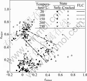
Fig.1 FLD (forming limit diagram) of AZ31 sheet at various temperatures
Fig.2 presents the microstructures of the material at warm temperatures. Figs.2(a-e) were obtained from specimens that were heated to the specific temperatures for 30 min followed by slow cooling. Figs.(a��-e��) were obtained from specimens that were similarly heated and simultaneously deformed to the forming limits at thecorresponding temperatures, followed by slow cooling. The grains were found to be equi-axed but different in magnitude. Fig.3 presents the average grain sizes of those microstructures. Grains without deformation increased as temperature increased by grain growth. Grains with deformation increased, and then gradually decreased up to 150 �� as recrystallization occurred. It seems that the abrupt decrease in grain size is related to the drastic increase in formability at this temperature.
3 Forming of hemispherical surface
The egg surface is similar to a hemispherical surface in geometry. Therefore, preliminary studies were performed, in which hemispheres were made with commercial aluminum sheet. Unlike pyramids or cones, the inclination angle of a hemispherical surface is variable, which makes the required strain variable as well. It has been known that this kind of surface can be formed by negative forming.
Initially, two different tool paths that moved in opposite directions were considered. In the ��In-Out�� path, the tool moves in a spiral pattern from the center to the periphery. In the ��Out-In�� path, the tool moves in a spiral pattern from the periphery to the center. However, it was found that in the ��In-Out�� method, the tool moved exclusively in the vertical direction at the pole of the hemisphere where the formability is the lowest, resulting in an occurrence of crack. It is important to remember that the deformation at the center is similar to that of axisymmetric stretching, and deformation at the periphery is similar to that of plane-strain stretching. Therefore, only the ��Out-In�� path was examined in detail.

Fig.2 Microstructures of AZ31 alloy at different temperatures with/without deforma- tion: (a, a��) 20 ��; (b, b��) 100 ��; (c, c��) 150 ��; (d, d��) 200 ��; (e, e��) 250 ��; (a-e) With- out deformation; (a��-e��) With deformation
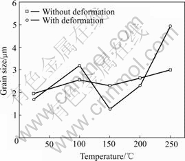
Fig.3 Variations of average grain size at different temperatures with/without deformation
An ��Out-In�� tool path was generated to form the hemispherical surface. The tool moved in a spiral pattern starting from the basal circle and ending at the pole of the final hemisphere. However, a crack occurred at the vicinity of the basal circle early in the process, where the required strain drastically increased, as shown in Fig.4. Therefore, other tool paths were considered in order to lower the required strain to prevent cracks. As shown in Fig.5, ��Path�� consists of a series of spiral patterns with gradually decreasing radii while ��Path �� makes use of an intermediate shape in the form of a cone, followed by a series of spiral patterns with gradually decreasing radii. The hemispheres were successfully formed without cracks using those paths as shown in Fig.6.
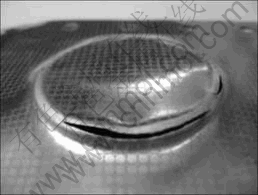
Fig.4 Sheet cracked at basal circle
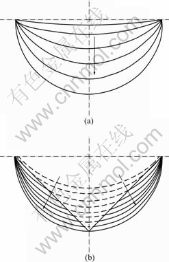
Fig.5 Tool paths �� and ��: (a) Series of spiral patterns; (b) Cone followed by a series of spiral patterns
4 Measurement of grid deformation
A transparent scale is usually used for the measurement of deformed grids. However, the measurements are limited in accuracy since it is difficult to locate and read the scale at a specific grid on a curved surface. To resolve these problems, flexible scale stickers were devised. These new scales were able to align easily with the curved surface, and adhere to the grid allowing for a more precise measurement. The scales were attached to the grids, and then photographed with a digital camera. The digital images were then enlarged on a CAD system in order to acquire an accurate measure- ment. Fig.7 presents deformed grids with a flexible scale sticker and measured lengths on a CAD system.
The longitudinal and the circumferential strains of deformed grids, corresponding to the major and the minor strains, respectively, were measured along the meridian of the hemisphere. The grids were initial circles measuring 2.54 mm in diameter and numbered from (1) to (10) starting at the pole. The measured strains of the hemispheres which were produced by Paths �� and �� are presented in Fig.8. In Path ��, the deformation produced in grids (1)-(6) was close to that of axisymmetric stretching, whereas in grids (7)-(10) it was close to that of plane-strain stretching. The deformation of cone forming in Path �� was close to that of plane-strain stretching at all grids. However, in the subsequent forming of a hemisphere, the deformation changed toward that of axisymmetric stretching.
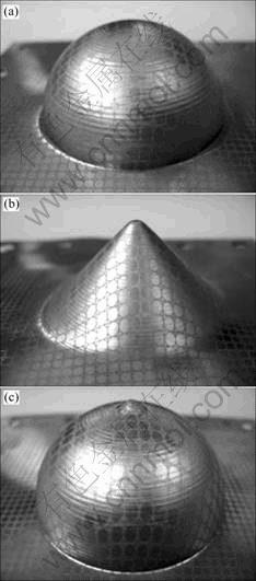
Fig.6 Shapes by incremental forming: (a) Hemisphere by Path ��; (b) Cone by Path ��; (c) Hemisphere by Path ��
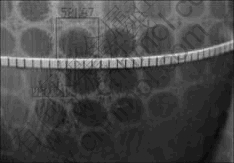
Fig.7 Photograph of deformed grids with flexible scale sticker attached
It is noted that the allowance in the formability remains more in the case of Path ��. This result implies that deformation is safer in Path �� than in Path ��with
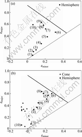
Fig.8 Deformations at several locations occurred during Path �� (a) and Path �� (b)
respect to the occurrence of cracks. Path �� is also superior to Path �� since it is critical to shorten the forming time, especially for the incremental forming at warm temperatures.
5 Forming of egg surface
An egg surface, as an example of a free surface, was attempted to form in this study in addition to analytical surfaces such as cones and hemispheres, in order to apply the concept of the reverse engineering to the incremental forming technique.
An egg shell was scanned to obtain point data of the surface which were then transformed to surface data, as shown in Fig.9. An inclined cone was introduced as the intermediate shape to form an egg surface with commercial aluminum sheet, as shown in Fig.10. The same tool path was then successfully applied to AZ31 sheet at 150 �� to form the egg surface, as shown in Fig.11. To maintain a constant temperature during forming, the sheet was continuously monitored and heated by hot air blowers.
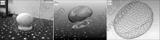
Fig.9 Procedure to obtain surface information by 3D scanning: (a) An egg; (b) Surface represented by points; (c) Surface represented by wire frames

Fig.10 Intermediate and final shapes with commercial aluminum sheet: (a) Inclined cone; (b) Egg shell
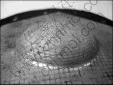
Fig.11 Final surface of egg with AZ31 sheet
6 Conclusions
1) At 150 ��, the values of ��major in the deformation of plane-strain stretching and axisymmetric stretching were found to be 0.55 and 0.27, respectively, and the grains were found to be approximately 1 ��m in size with severe deformation. Therefore, the drastic increase in formability can be attributed to the abrupt decrease in grain size, in addition to the activation of the slip systems on prismatic and pyramidal planes.
2) The incremental forming technique was applied to AZ31 sheet at 150 ��. An egg surface was taken as an example of a free surface. After examining various tool paths using commercial aluminum sheets, the best tool path was successfully applied to produce the egg surface with AZ31 sheet. The tool path consisted of cone forming followed by a series of tool paths in spiral patterns. The sheet was heated by hot-air blowers to maintain a consistent temperature during forming.
Acknowledgement
Authors thank Mr. J. H. Kee for his help in carrying out the experiments.
References
[1] CHINO Y, IWASAKI H, MABUCHI M. Stretch formability of AZ31 Mg alloy sheets at different testing temperatures [J]. Materials Science and Engineering A, 2007, 466: 90-95.
[2] ISEKI H, KUMON H. Forming limit of incremental sheet metal stretch forming using spherical rollers [J]. J JSTP, 1994, 1336: 35- 40.
[3] ISEKI H. An approximate deformation analysis and FEM analysis for the incremental bulging of sheet metal using a spherical roller [J]. J Mater Process Technol, 2001, 111: 150-154.
[4] HIRT G, AMES J, BAMBACH M, KOPP R. Forming strategies and process modeling for CNC incremental sheet forming [J]. CIRP Manufacturing Technology, 2004, 53: 203-206.
[5] DUFLOU J R, CALLEBAUT B, VERBERT J, DE BAERDEMAEKER H. Laser assisted incremental forming: Formability and accuracy improvement [J]. CIRP Annals �C Manufacturing Technology, 2007, 56: 273-276.
[6] ATTANASIO A, CERETTI E, GIARDINI C, MAZZONI L. Asymmetric two points incremental forming: Improving surface quality and geometric accuracy by tool path optimization [J]. J Mater Process Technol, 2008, 197: 59-67.
[7] AMBROGIO G, DE NAPOLI L, FILICE L, GAGLIARDI F, MUZZUPAPPA M. Application of incremental forming process for high customized medical product manufacturing [J]. J Mater Process Technol, 2005, 162/163: 156-162.
[8] JI Y H, PARK J J. Formability of magnesium AZ31 sheet in the incremental forming at warm temperature [J]. J Mat Process Technol, 2008, 201: 354-358.
[9] PARK J J, KIM Y H. Fundamental studies on the incremental sheet metal forming technique [J]. J Mater Process Technol, 2003, 140: 447-453.
(Edited by YANG Bing)
Foundation item: Project(R01-2006-000-11076-0) supported by the Basic Research Program of the Korea Science and Engineering Foundation; Project supported by the 2007 Hongik University Research Fund, Korea
Corresponding author: J. J. PARK, E-mail: jjpark@hongik.ac.kr

