
Interface electron structure of Fe3Al/TiC composites
PANG Lai-xue(ЕУАґС§)1, SUN Kang-ning(ЛпїµДю)1, 2, SUN Jia-tao(ЛпјТМО)1,
FAN Run-hua(·¶Иу»Є)1, 2, REN Shuai(ИО Л§)1
1. Key Laboratory of Engineering Ceramic of Shandong Province, JiЎЇnan 250061,China
2. Key Laboratory of Liquid Structure and Heredity of Materials, Ministry of Education, Shandong University,
JiЎЇnan 250061, China
Received 29 June 2005; accepted 31 October 2005
Abstract: Based on YUЎЇs solids and molecules emperical electron theory(EET), interface valence electron structure of TiC-Fe3Al composites was set up, and the valence electron density of different atomic states TiC and Fe3Al composites in various planes was determined. The results indicate that the electron density of  is consistent with that of (110)TiC in the first-class approximation, the absolute value of minimum electron density difference along the interface is 0.007 37 nm-2, and the relative value is 0.759%.
  preferred orientation is believed to benefit the formation of the cuboidal shape TiC. In the other hand, it shows that the particle growth is accompanied by the transport of electron, the deviation continuity of electron density intrinsically hinders the grain growth. The electron density of (100)TiC is not consistent with Fe3Al arbitrary crystallographic plane, thus it well explains that the increased titanium and carbon contents do not increase the size of large particles. The crystallographic orientation of
  will improve the mechanical properties. Therefore interface electron theory is an effective theoretical implement for designing excellent property of composites.
Key words: TiC/Fe3Al composite; intermetallic matrix composites; ceramic particles; YUЎЇs theory; interface; electron density
1 Introduction
Recently a few studies[1-3] have been carried out to utilize carbides or borides as reinforcements in iron aluminides, thus improving their mechanical properties. Additionally, an intermetallic matrix reinforced with ceramic phase might make it possible to overcome some of the problems that prevent the use of monolithic intermetallic alloys[4]. Among them titanium carbide with high hardness, low density and low chemical reactivity was found to be a suitable reinforcement for wear and high temperature application.
The nature of the interface between reinforcement and matrix plays a very important role in determining the properties. Differences in atomic structure, chemical ingredients, atom bonding manners between the matrix and the reinforcement, the interface characteristics has great disparities with the two sides of interface. Material interfaces bonding is virtually atom bonding, depending on atoms arrangement and electron density distributions. From the viewpoint of atom scale, if we understand the interface microstructure and the interface stability, we would grasp the relationship between the interface and material properties, thus take advantage of Ў°interface engineeringЎ±[5] to develop the composites. Cheng[6] proposed the revised TFD (Thomas-Fermi-Dirac) model, the electron boundary condition is ascertained, namely electron density must be continuing among the atom bonding planes. This is determined by quantum condition of wave function continuity. Based on it, LIU et al[7] proposed a method to calculate the biphase interface valence electron structure, and found that the electron density of (111)¦Г //(110)¦Б interface in steel is continuous[8]. This confirmed the existence of the above mentioned electron boundary condition. In this brief communication, emphasis will be made to study the interface electron structure between reinforcement TiC and Fe3Al matrix, and to verify whether consistent crystallographic orientation relationships exist between TiC and Fe3Al matrix. The valence electron structure(VES) of TiC ceramic phase and Fe3Al intermetallic phase in TiC/Fe3Al composite is calculated with YUЎЇs EET. 2 VES calculation
2.1 VES of Fe3Al and valence electron density
The DO3 cell structure of Fe3Al is shown in Fig.1,  (m3m) type of space group. One DO3 cell consists of four A2 (bcc) cells and four B2 cells, belongs to face centered cubic structure. Its lattice constant a is 0.578 nm. The Fe atoms located in the center of cell interior, or in the center of cell edge and the top of the cell are expressed as Feўс. The Fe and Al atoms at the diagonal 1/4 and 3/4 of the cell interior are expressed as
  and Al, respectively. Therefore the structure formula of Fe3Al can be written as
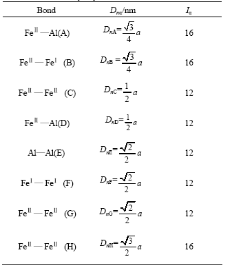
  . Only eight kinds of covalent bonds in DO3 structure are considered. The experimented bond lengths (Dn¦Б) and equivalent bond numbers (I¦Б) are listed in in Table 1.
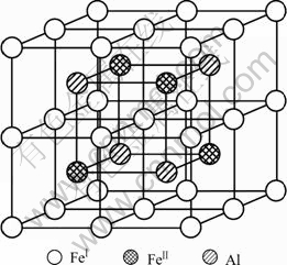
Fig.1 Unit cell of DO3 structure Fe3Al
Electron density of various crystallographic planes of Fe3Al is calculated. The atoms on the (100) plane form only one kind of bond, i.e.  . The equivalent bond number in (100) plane is 4, the total covalent electrons on (100) crystal plane is
  , and the area of (100) plane is S(100)=a2
Thus the electron density of (100) crystal plane is
 (1)
(1)
There are four kinds of bonds on (220) crystal planes, i.e.  ,
,  ,
,  and
and  . The numbers of equivalent bond are 4, 4, 2, 2, respectively. Therefore, the total number of covalent electron on (220) plane is
ЎЖ
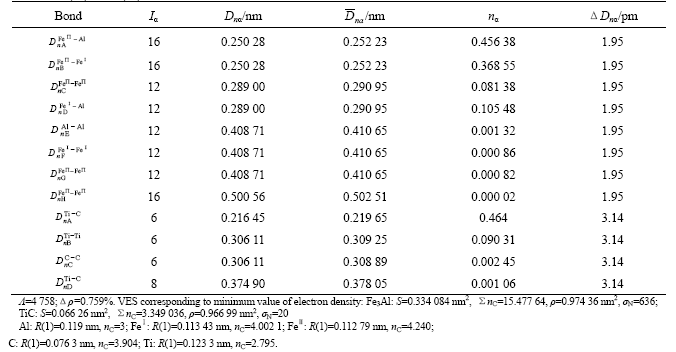
Table 1 Experimental covalent bond distances and equivalent bondnumbers of binary Fe3Al unit cell
The area of the (220) crystal plane of Fe3Al is S(220)= a2
a2
So the electron density of (220) crystal plane is
 (2)
(2)
,  and Al atoms arrange orderly on the (111) crystal plane, interatomic distances are the third near neighborhood, their covalent electron numbers are relatively scarce. Thus the electron density of (111) crystal plane can be neglected in first-class approximately.
According to the method of bond length difference(BLD)[9] in EET, the data in the binary hybridization list of Fe and the binary hybridization list of Al can be scanned using a computer so as to find all resolutions that satisfies the criterion of EET:¦¤Dn¦БЈј0.005 nm. The result shows there are 636(¦ТN) kinds of resolutions. Here let ¦ТN represent the number of all probable groups of atom state. Substitute covalent electron numbers: n¦Б distributing the mentioned bonds into Eqns.(1) and (2). The electron density value scale of (100) and (220) crystal planes are 0.783 8-1.814 8 nm-2, 6.475 8-8.969 8 nm-2, respectively.
2.2 VES of TiC and valence electron density
TiC cell is B1 type of structure, Fm3m type of space group, as shown in Fig.2. Its lattice constant a is 0.216 45 nm. According to Ref.[10], only 4 kinds of covalent bonds in B1 structure are considered which are precise enough for ordinary research. Their names, experimented bond lengths and equivalent bond numbers are as follows:
 =a, IA=6;
 IB=6;
IB=6;
 IC=6;
IC=6;
 , ID=8
Fig.2 Unit cell of B1 structure TiC
There are three kinds of bonds distributing on the (100) crystal plane, namely 
 and
and  . Their equivalent bond numbers are 4, 2, 2, respectively. The area of (100) crystal plane of TiC is S(100)=a2
Therefore the electron density of its (100) crystal plane is
 (3)
(3)
But there are four kinds of bond distributing on (110) crystal plane, namely 

 and
and  . Their equivalent bond numbers are 2, 1, 1, 4, respectively. The area of the (110) crystal plane of TiC is S(110)=
Therefore the electron density of its (110) crystal plane is
 (4)
(4)
Otherwise, only one kind of bond distributing on the (111) crystal plane, which is CЎЄC bond with equivalent bond number of 3. The area of (111) crystal plane of TiC is S(111)=
Thus the electron density of its (111) crystal plane is
 (5)
(5)
According to Ref.[11], atom Ti is A-type hybridization. The results show that ¦ТN =20 resolutions satisfy the criterion of EET. The numbers of covalent electron of probable atom state are substituted into Eqns.(3), (4) and (5). The electron density value scale of (100), (110), (111) crystal planes are 34.039 9- 47.229 8 nm-2, 0.755 3-1.048 1 nm-2, 0.177-0.245 5 nm-2, res- pectively.
3 VES of biphase interface
3.1 Continuous interface electron density of atom state groups
According to LiuЎЇs theory of interface valence electron structure, the interface electron density is defined as continuity in first-class approximately, namely ¦¤rЈј10% is regarded as continuity. However ¦¤rЈѕ10% is defined as deviation from continuity. These definitions are significant in material fields[12]. The relative covalent electron density difference between TiC(uvw)//Fe3Al (hkl) interfaces is
 (6)
(6)
According to the criterion: ¦¤rЈј10%, the number of atom state groups ¦Л which keeps continuous interface electron density can be counted.
The electron density of  and (110)TiC can be scanned using a computer to find ¦Л=4 758. Here, it is referred that the more ¦Л is, the more stable the structure is when the condition changes[8].
3.2 Optimal states of interface electron density continuity
The atom states corresponding to the minimum value of electron density difference is listed in Table 2. As for  interface, absolute value of minimum electron density difference along the interface is 0.007 37 nm-2, and relative value is 0.759%. Here
 ЈЅ0.966 99 nm-2, sTi=12, sC=5;
 =0.974 36 nm-2,
  =11,
=11,
 ЈЅ12, sAl=6
 =0.759%
Table 2 TiC(110)/Fe3Al (100) interface valence electron structure
However, as for TiC, the atom stable states are: Ti atom is at the 13th level of A-type hybridization, and C atom is at the 6th hybrid level. Meantime the electron density of (110) crystal plane is 1.016 5 nm-2. With regard to Fe3Al, atom stable states are: Feўсand Feўт are at the 11th level and the 14th level of B-type hybridization, respectively. Al is at the 3rd hybrid level. Meantime the electron density of (100) crystal plane is 0.874 7 nm-2. That is to say when TiC phase and Fe3Al phase are the most stable state, the biphase interface electron density deviates from continuity, the percentage value of minimum electron density difference along the interface is 15%. So the atom state, which keeps the electron density continuous, is a series of atomic exited-state.
Additionally, Al atom is at 6th level compared with the 2nd level of the document[13]. In composites, Al will supply more covalent electrons to form bond, result in fraction of covalent bond increasing in iron aluminides. Thus coherent or semi-coherent interface may be formed between iron aluminides phase and titanium carbide phase leading to strengthen the interface.
4 Composite materials fabrication techni- ques
Fe3Al/TiC composites can be fabricated by mechanical alloying processing and in-situ processing techniques. With regard to the former, the pre-mixed powder was processed by mechanical alloying followed by hot pressure sintering. Simple mixed powders undergo the formation of intermediate phases, it will have affluence on the interface bonding. In contrast to mechanical alloying processing, an in-situ processing techniques[14] during composite fabrication have a potential for good mechanical properties because the interface between the matrix and reinforcement may have a good bonding strength due to the avoidance of contamination by oxidation and other detrimental surface reaction.
The large TiC particles tend to precipitate from the melt with the shape of cuboidal, spherical, starlike and dendritic crystal due to the growth environmental diversities. Formation mechanism of the cuboidal shape TiC in the liquid iron-aluminide alloy is not clear at present[13]. Additionally, it is also found that increased titanium and carbon contents do not increase the size of large particles. One possible explanation[12] is that this phenomenon may result from the difference in the interfacial free energy between different phases. If surface energy between TiC particles with different orientations is larger than two times that between liquid iron-aluminum alloy and TiC particle, TiC particles will not agglomerate. Some studies[15, 16] also show that cuboidal TiC particles with (100) facets precipitate in iron melt by in-situ processing. However, 12-faced polyhedron TiC particles were reported to form in aluminum melt by in-situ processing.
When TiC particle bonds with metallic phase, the crystal will grow along the specified crystallographic orientation of hard core. But the crystallographic orientation relation is not determined exclusively. From Table 2 it can be found that (110)TiC//(100)FeAl interface has continuous interface electron density and relatively small ¦¤rmin. This result just confirms the fact that TiC particles grow on the non-close-packed plane, the final shape is cuboidal. (110)TiC//(100)FeAl crystallographic orientation relationship is believed to the formation mechanism of the cuboidal shape of TiC.
Otherwise, the results show the maximum electron density of (100)TiC deviates from continuity with the arbitrary crystal plane of Fe3Al. From the viewpoint of CHENG-LIU theory, crystal particle growth is accompanied by the electrons transporting, the electron density deviation from continuity can lead to constraint the particle growth. It is well explained that the increased titanium and carbon contents do not increase the size of large particles.
5 Conclusions
1) B1 structure of TiC has 20 probable states of Ti atom and C atom, D03 structure of Fe3Al has 636 probable states of Fe atom and Al atom.
2) (110)TiC//(100)FeAl interface has continuous interface electron density; the number of atom state groups ¦Л=475 8. Absolute value of minimum electron density difference along the interface is 0.007 37 nmЈ2, and relative value is 0.759%. Here
 ЈЅ0.966 99 nm-2;
 =0.974 36 nm-2.
Atomic state is: Ti is at the 12th level of A-type hybridization, and C is at the 5th hybrid level. Feўсand Feўт are at the 11th level and the 12th level of B-type hybridization, respectively; Al is at the 6th hybrid level.
3) From the viewpoint of the continuity and deviation from continuity of interface electron density, it is well explained that the formation mechanism of cuboidal shape of TiC particle and the micromechanisms of small size of TiC particle. This method of investigating the biphase interface is heuristic for other intermetallic matrix composites.
Reference
[1] TANG Wen-ming, TANG Hong-jun, ZHENG Zhi-xiang, WU Yu-cheng, DONG Ji-ling. Progresses in studies on Fe-Al intermetallic matrix composites [J]. Trans Nonferrous Met Soc China, 2003, 13(4): 811-813.
[2] Schneibel J H, Carmichael C A, Specht e d, SUBRAMANIAN R. Liquid-phase sintered iron aluminide- ceramic composites [J]. Intermetallics, 1997, 5(1): 61-67.
[3] Alman D E, Tylczak J H, Hawk J A, SCHNEIBEL J H. An assessment of the erosion resistance of iron-aluminide cermets at room and elevated temperatures [J]. Mater Sci Eng A, 2002, A329-331: 602-608.
[4] Sundar R S, Baligidad R G, Prasad D H, SASTRY D H. Processing of iron aluminides [J]. Mater Sci Eng A, 1998, A258(1-2): 219-228.
[5] YE Heng-qiang. Material Interfaces Structure and Properties [M]. Beijing: Science Press, 1999. 254.(in Chinese)
[6] CHENG Kai-jia. Application of TFD model and YuЎЇs theory to material design [J]. Progress in Nature Science, 1993, 3(5): 211-230.
[7] LIU Zhi-lin, LI Zhi-lin, LIU Wei-dong. Interface Electron Structure and Interface Properties [M]. Beijing: Science Press, 2002. 85.(in Chinese)
[8] LIU Zhi-lin, LI Zhi-lin, SUN Zhen-guo. Electron density of austenite/martensite biphase interface [J]. Chinese Science Bulletin, 1996, 41(5): 367.(in Chinese)
[9] ZHANG Rui-lin. The Empirical Electron Theory of Solids and Molecules [M]. Changchun: Jilin Science and Technology Press, 1993. 83.(in Chinese)
[10] FUN Run-hua, YIN Yan-sheng, SUN Jia-tao, WANG Xin, CHEN Shou-gang. FeAl/TiC composite interface electron structure [J]. Progress in Nature Science, 2004, 14(3): 307-311.(in Chinese)
[11] WANG Huan-rong, YE Yi-fu, MIN Guang-hui. TiC valence electron structure and analysis of properties [J]. Chinese Science Bulletin, 2001, 46(3): 58-63.(in Chinese)
[12] SUN Zhen-guo, LI Zhi-lin, LIU Zhi-lin. Calculation of biphase interface electron density in alloy [J]. Chinese Science Bulletin, 1995, 40(24): 2219-2222.(in Chinese)
[13] SUN Kang-ning, YIN Yan-sheng, LI Ai-min. Intermetallics/ Ceramics Matrix Composites [M]. Beijing: China Machine Industry Press, 2002. 82-84.(in Chinese)
[14] KO S H, HANADA S. In-situ production and microstructures of iron aluminide/TiC composites [J]. Intermetallics, 1999, 7(8): 953-955.
[15] KO S H, PARK B G, Hashimoto H, ABE T, PARK Y H. Effect of MA on microstructure and synthesis path of in-situ TiC reinforced FeЁC28at%Al intermetallic composites [J]. Mater Sci Eng A, 2002, A329-331: 78-83.
[16] Krasnowski M, Witek A, Kulik T. The FeAl-30%TiC nanocomposite produced by mechanical alloying and hot-pressing consolidation [J]. Intermetallics, 2002, 10(4): 373-375.
Foundation item: Project(Q99F01) supported by the Natural Science Foundation of Shandong Province, China
Corresponding author: PANG Lai-xue; Tel: +86-531-88392439; E-mail: laixuepang@hotmail.com
(Edited by LONG Huai-zhong)

