����Ħ������ȫ���̲���������Ϊ����ֵģ��
��Դ�ڿ����й���ɫ����ѧ��(Ӣ�İ�)2018���11��
�������ߣ������� �߶�־ ������ ������
����ҳ�룺2324 - 2334
�ؼ��ʣ�����Ħ����������Ԫģ�⣻�ʵ���٣���������
Key words��friction stir welding; finite element simulation; tracer particles; material flow
ժ Ҫ�����ڹ�����ѧ���ۣ�����ABAQUS����Ԫ������������Ħ������(FSW)ȫ�����������ģ�ͣ������ʵ���ټ���ģ���о�FSWȫ���̲���������Ϊ�������������������Χ���ϵ��˶���ʽΪ�����˶��������ϲ����²����������Բ�ͬ��������ʽ���ϲ��ֲ���������Ӱ���»����������˶����²��ֲ����ڽ������Ӱ���»������˶�����������Χ�����ʵ�������ٶȸ��ڽ�����ײ��ʵ�ġ����Ͽ��ƽ�������ת���ܣ�ģ��������ʾ�����ӵ�ʵ��۲������Ǻϡ�
Abstract: A finite element model based on solid mechanics was developed with ABAQUS to study the material flow in whole process of friction stir welding (FSW), with the technique of tracer particles. Simulation results indicate that the flow pattern of the tracer particles around the pin is spiral movement. There are very different flow patterns at the upper and lower parts of the weld. The material on the upper surface has the spiral downward movement that is affected by the shoulder and the lower material has the spiral upward movement that is affected by the pin. The velocity of the material flow on the periphery of the stirring pin is higher than that at the bottom of the stirring pin. The material can be rotated with a stirring pin a few times, agreeing well with the previous experimental observation by tungsten tracer particles.
Trans. Nonferrous Met. Soc. China 28(2018) 2324-2334
En-zhi GAO1,2, Xing-xing ZHANG1, Chun-zhong LIU2, Zong-yi MA1
1. Shenyang National Laboratory for Materials Science, Institute of Metal Research, Chinese Academy of Sciences, Shenyang 110016, China;
2. College of Material Science and Engineering, Shenyang Aerospace University, Shenyang 110136, China
Received 1 August 2017; accepted 8 February 2018
Abstract: A finite element model based on solid mechanics was developed with ABAQUS to study the material flow in whole process of friction stir welding (FSW), with the technique of tracer particles. Simulation results indicate that the flow pattern of the tracer particles around the pin is spiral movement. There are very different flow patterns at the upper and lower parts of the weld. The material on the upper surface has the spiral downward movement that is affected by the shoulder and the lower material has the spiral upward movement that is affected by the pin. The velocity of the material flow on the periphery of the stirring pin is higher than that at the bottom of the stirring pin. The material can be rotated with a stirring pin a few times, agreeing well with the previous experimental observation by tungsten tracer particles.
Key words: friction stir welding; finite element simulation; tracer particles; material flow
1 Introduction
Material flow during friction stir welding (FSW), a solid-state joining technique invented by The Welding Institute of the United Kingdom in 1991, is highly complex and is one of the key factors that influence the joint efficiency of FSW [1-4]. MISHRA and MA [5] reviewed material flow behavior during FSW and pointed out that it is difficult to use experimental methods for visualization of the material flow in the stir zone. Therefore, many numerical models of FSW processes have been developed to study the material flow.
Different theories such as computational fluid dynamics (CFD) and computation solid mechanics (CSM) have been applied to simulating the material flow in the FSW process. The theory of fluid mechanics is a numerical method based on the Euler description. In the process of calculation, the grid does not deform with the material, avoiding excessive distortion, which can accurately contain complex pin geometries [6-13]. However, the CFD model assumes that the material is a non-Newtonian fluid, so the history information of the deformation cannot be obtained.
CSM models can track the motion of material points in addition to the temperature, strain and stress distribution. Although a variety of FSW models have been developed, few of these have studied the material flow behavior in detail. XU et al [14] first reported CSM finite element model to simulate the FSW process. The material flow behavior is predicted and compared well with the experimental observation. DENG and XU [15] developed a two-dimensional (2D) CSM finite element model. The velocity field and material flow behavior are predicted. Simulation results show that the material points in front of the pin tend to rotate with pin and deposit on the trailing side of the pin. XU and DENG [16] developed solid mechanics based 2D and three- dimensional (3D) finite-element procedures to simulate the FSW process. The results of numerical simulations are used to understand the texture patterns.
SCHMIDT and HATTEL [17] proposed a 3D thermo-mechanical finite-element model to simulate the steady FSW process using the arbitrary Lagrangian-Eulerian (ALE) formulation. The velocity field and the equivalent plastic strain fields are calculated to evaluate the material deformation. ZHANG and ZHANG [18,19] presented a similar model using the ALE formulation and Coulomb��s friction law. Tracer particle technology is applied to investigating the material flow during FSW. It was found that tracer particles on the top surface do not enter into the weld and just pile up at the border of the weld, which is the reason of the formation of the weld flash. DIALAMI et al [20] proposed a methodology to study the effects of the pin geometry in the FSW process. In this approach, a Lagrangian formulation is used for the pin, an ALE formulation is used at the stir zone of the work-piece, and an Eulerian formulation is used in the remaining part of the work-piece. The forces, temperature distribution and material flow during the FSW process are elucidated. This coupling strategy is also used for the computation of residual stresses in the FSW process [21].
The models listed above only simulated either the moving (or welding) stage or the dwell and moving stages but did not treat the entire FSW process. The plunge stage is the foundation of the FSW process to reach a stable welding state, and it should not be ignored in the modeling. The multi-physics mode proposed by HAMILTON et al [22] has successfully simulated the whole FSW process, including plunge, dwell and traverse stages. The temperature field, stress and plastic strain field are obtained by the model. However, material flow behavior is still not fully understood.
In this study, a 3D thermo-mechanical simulation of the whole FSW process is presented to predict the material flow pattern. The primary novelty of this study is the two-stage method. In the plunge stage, a Lagrangian adaptive mesh domain is created for the entire workpiece. In the steady welding stage, an Eulerian adaptive mesh domain is used to model the material flow. The material flow behavior at different locations around pin by tracer particle technique is analyzed. The presented results include displacement, velocity and flow trajectory of the tracer particles. This work provides very useful qualitative and quantitative understanding for the FSW process.
2 Model description
The commercial finite element software ABAQUS is used to model the whole FSW process. The present model is composed of a deformable workpiece and a rigid stirring pin, the workpiece is assumed to be elasto-plastic material and the pin is considered as a rigid.
The equilibrium equation for the mechanical response of the process reads [17]:
 (1)
(1)
where �� is the density, c is the damping coefficient, k is the stiffness coefficient, p is the body force, u,  and
and  are the nodal displacement, velocity and acceleration vectors, respectively.
The heat transfer equation for the workpiece is written as
 (2)
(2)
where C is the specific heat capacity,  is the temperature rate, T is the temperature, �� is the thermal conductivity and Q is the heat source.
The heat source Q is computed by
Q=Pf+rpl (3)
where Pf is the rate of frictional energy dissipation in the coupled thermo-mechanical surface interactions, rpl is the rate of plastic strain energy dissipation.
The rate of frictional energy dissipation Pf is computed by
 (4)
(4)
where �� is the frictional stress and  is the slip rate.
The classical Coulomb��s friction model is used to describe the contact behavior between the pin and the workpiece. The critical condition for the transformation of the friction condition from sticking to sliding is defined by
��critical=��p (5)
In the present model, the friction coefficient �� is set to be 0.3 according to the reference [23].
The rate of plastic strain energy dissipation rpl is computed by
 (6)
(6)
where �� is the fraction of plastic energy dissipation, Sij is the deviatoric stress tensor and  is the plastic strain rate tensor.
A temperature and strain rate dependent constitutive model is applied by using the elasto-plastic Johnson- Cook material law, which is given by
 (7)
(7)
where  and
and  are the effective plastic strain and strain rate, respectively,
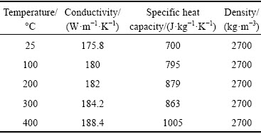
  is the reference strain rate (typically 1.0 s-1), Tr is the reference temperature, Tm is the melting point, and A, B, n, C and m are material constants. These constants for 6061Al alloy are listed in Table 1 [24]. The other thermal and mechanical properties of 6061Al alloy used in this model are listed in Table 2 [25].
Table 1 Material constants in Johnson-Cook model for 6061Al alloy
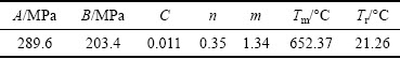
Table 2 Temperature dependent material properties of 6061Al alloy used in model
The geometry sizes of the workpiece are 40 mm �� 40 mm �� 3 mm. The boundary conditions of the developed model of FSW are shown in Fig. 1. A 3D temperature-displacement coupled element with eight nodes, reduced integration and hourglass control, C3D8RT, is used in the model. The geometry size of the pin is shown in Fig. 2.
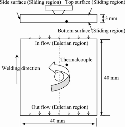
Fig. 1 Geometry and boundary conditions of model
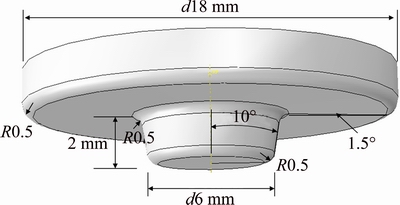
Fig. 2 Geometry of welding tool
The material near the pin-workpiece interface experiences very large deformations due to the rotation of the pin. ALE technique is used to avoid mesh distortions. It maintains a high-quality mesh under severe material deformation by allowing the material to flow into or out mesh.
In the present model, the inflow and outflow surfaces of the workpiece are also considered as Eulerian region type, in which the mesh does not follow the material movement. The top, bottom and side surfaces of the workpiece are considered as a sliding region type, in which the mesh is constrained to move with the material in the direction normal to the boundary region but it is unconstrained in the direction tangential to the boundary region, as shown in Fig. 1. The whole process of FSW is modeled: 1 s plunge period and 8 s welding period. The rotation rate is 400 r/min, and the welding speed is 3 mm/s.
In the model, the convective heat transfer boundary condition is applied. The heat transfer coefficient for the bottom surface is set to be 1000 W/(m2��K), while that for the rest surfaces is set to be 10 W/(m2��K).
3 Friction stir welding and temperature measurement
The 6061-T6 Al plates with sizes of 300 mm ��80 mm �� 3 mm were welded parallel to the rolling direction, at a welding speed of 3 mm/s with a rotation rate of 400 r/min. The diameters of the shoulder and the pin are 18 and 6 mm, respectively. In order to verify the present model, temperature was measured during FSW process. A K-type thermocouple was used to measure the temperature, which was located on the advancing side, 5 mm away from the pin center on the bottom surface. The location of the thermocouple is shown in Fig. 1.
4 Results and discussion
4.1 Temperature distribution
Figure 3 shows the predicted temperature field on the top surface of the workpiece after steady welding for 3 s. It can be seen that the maximum temperature is 472 ��C, which is lower than the melting point of the material. TANG et al [26] studied the FSW process of 6061 aluminum alloy. The maximum temperature during the FSW process with a rotation rate of 400 r/min and a welding speed of 2 mm/s was measured to be about 450 ��C, which is very close to the simulation results in this work.
In order to further verify the model, a thermocouple is preburied 5 mm away from the pin center on the bottom surface to measure the temperature history profile. Because the simulated stable welding time is only 8 s, in order to better compare with the measured results, the ��temperature-time�� curve is transformed into a ��temperature-distance�� curve. The ��distance�� equals the ��time�� multiplying by the ��welding speed��. As shown in Fig. 4, the predicted temperature-distance curve along the line 5 mm away from the pin center on the bottom surface agrees with the measured results very well. The maximum temperature is 383 ��C and occurs near the pin center.

Fig. 3 Temperature field after steady welding for 3 s
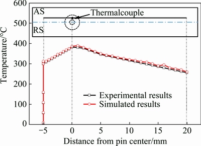
Fig. 4 Comparison between calculated and measured temperature along line 5 mm away from pin center on bottom surface
4.2 Material flow behaviors
Tracer particles can be defined to track material points as they pass through the adaptive mesh domain in ABAQUS. Figure 5 shows the initial locations of the tracer particles. Tracer particles p1-p4 are located at the weld center; particles p5-p8 and p9-p12 are located on the advancing side (AS) and retreating side (RS), respectively, with a distance of about 2 mm from the center line. Particles p13-p16 and p21-p24 are located on the AS and the RS, respectively, with a distance of about 5 mm from the center line that is outside the pin width. Similarly, particles p17-p20 and p25-p28 are located on the AS and the RS, respectively, with a distance of about 8 mm from the center line that is outside the pin width. Tracer particles can be released from the locations of the nodes. Each release of tracer particles is termed as particle birth.
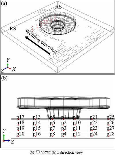
Fig. 5 Initial locations of defined tracer particles
Figure 6 shows the 3D material flow obtained using the tracer particle p1 on the top surface. Figure 6(a) shows the initial location of particle p1 sited at the weld line and Figs. 6(b)-(f) trace the birth particles during FSW. As revealed, the tracer particle is dragged by the pin to the wake and the spiral downward movement is observed. The material points can rotate with the welding pin for several revolutions. This type of material flow pattern has been observed experimentally via two pairs of X-ray transmission systems based on tungsten tracer particles [27]. The numerical simulation results agree very well with the experimental observation.
Figure 7 shows the two-dimensional displacement graph of the birth particle p1. It can be seen that the tracer particles slough off on the AS after several rotations. EDWARDS and RAMULU [28] investigated the material flow behavior of Ti alloys during FSW by embedding refractory alloy powder into the weld line. It was revealed that the tracer material that starts at the centerline of the weld was deposited in the AS of the weld zone. In order to accurately observe the rotation time, the displacement-time curve of the same birth particle in the transverse direction is shown in Fig. 8. The curve has wave, which is due to the difference in the displacements between the AS and the RS. A wave means a rotation, it can be seen that the tracer particle rotated around the pin eight times.
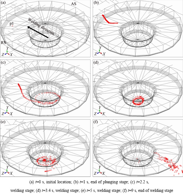
Fig. 6 Material flow patterns of particle p1 in different time
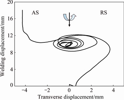
Fig. 7 Two-dimensional displacement graph of birth particle p1
The rotation time around the pin was also reported in a previous study [27], in which the tungsten tracer particles were used to trace material flow in FSW of a pure aluminum (1050 Al alloy). The experimental observation showed that the tungsten tracer particles rotated around the pin seven times. Despite the difference in the rotation numbers due to the different work-piece materials and welding parameters, the modeling result agrees very well with the experimental data.
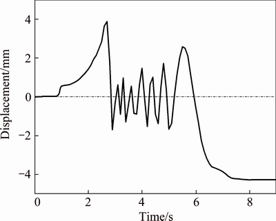
Fig. 8 Displacement-time curve of birth particle p1 in transverse direction
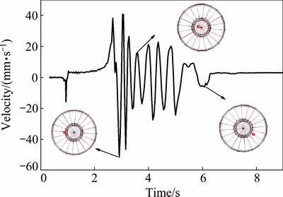
Fig. 9 Velocity of birth particle p1 in welding direction
The velocity of the same birth particle p1 in the welding direction is shown in Fig. 9. The velocity fluctuation frequency in the welding direction is consistent with the displacement fluctuation frequency in the transverse direction, which indicates the rotation time of the particle. There is no significant difference in the velocity at the plunge stage, and the velocity of the particle gradually increases as it is close to the center of the pin at the initial stage of the welding. The maximum velocity reaches 52 mm/s. At this time the particle is located at the periphery of the stirring pin, which has been also mentioned in the CFD model presented by SU et al [29]. Their results showed that the maximum velocity is at the edge of the flat area, but the particle exact location and velocity-time curve are not indicated. When the particle rotates to the bottom of the stirring pin, the velocity is reduced. It is considered that the velocity of the material flow is affected by both the pin and the shoulder. Therefore, the velocity at the periphery of the stirring pin is higher than that at the bottom of the stirring pin. Then, the tracer particle gradually moves to the outer side of the stir zone due to the centrifugal force. Without the effect of the pin, the velocity is obviously decreased.
Figure 10 shows the velocity at the locations of p5 and p9 in the welding direction. It can be seen that the velocity at location p9 (RS) is higher than that at location p5 (AS), which validates the results reported by MORISADA et al [27]. It can be easily explained by the relative velocity between the welding direction and the rotation direction of the pin.
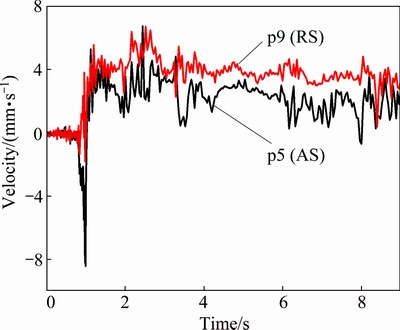
Fig. 10 Velocity at locations of p5 and p9 in welding direction
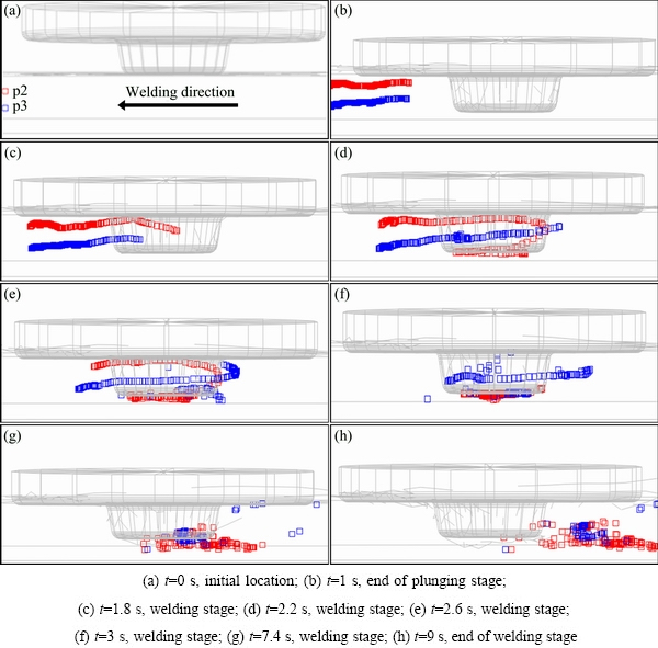
Fig. 11 Material flow patterns of particles p2 and p3 in different time
The material flows in the different depths of the welded plate are shown in Fig. 11. It can be seen that the tracer particle p2 in the middle of the weld has a spiral downward movement similar to the particle p1 on the top surface. At the bottom of the weld, the particle p3 first has a spiral upward movement and then a spiral downward movement. One reason for this is that the upper material is affected by the shoulder and the lower material is mainly affected by the pin.
Figure 12 shows the final position of the tracer particles in the different depths of the welded plate. It can be seen that the material near the top surface of the weld (p1, p2) is pushed across the weld centerline and deposited on the AS; the material near the bottom of the weld (p3) enters into the AS; the material near the bottom of the workpiece (p4) has a curved trajectory around pin and deposited on the RS. The reason for this behavior is the result of frictional force induced by the shoulder. The friction between the shoulder and top surface causes the upper material temperature to be higher than the bottom material temperature. So the upper material is more easily stirred. LORRAINA et al [30] performed FSW experiments using two different pin profiles (unthreaded pin and classical threaded pin). These two kinds of pins induced the same flow features, that is, upper material of the weld was deposited on the AS and lower material of the weld was deposited on the RS. These findings are consistent with the simulation results in this study.
In order to study the flow patterns of particles in the horizontal direction, the flow traces of particles p6 and p10 are shown in Fig. 13. It can be seen that particle located on the AS in front of the pin (p6) rotates around the pin and eventually all of them flow into the AS after several rotations. Similarly, the particles that are located on the RS in front of the pin also flow into the AS. In a similar model developed by ZHANG and ZHANG [18], the particles located on the RS do not flow into the AS and are just rotated by the pin to the rear. However, their work did not pay much attention in time histories of material point.
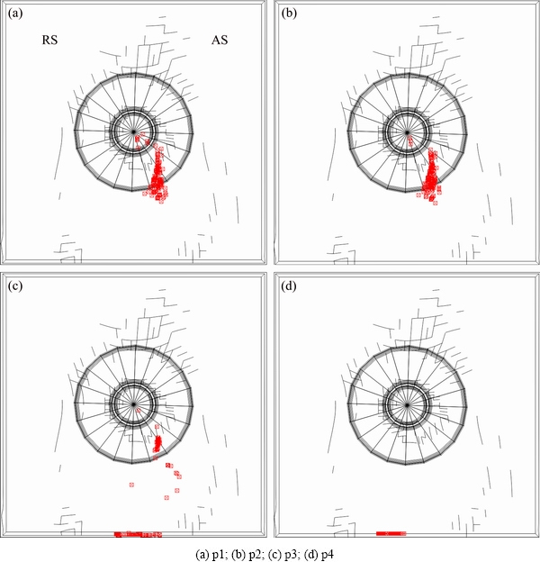
Fig. 12 Final positions of tracer particles
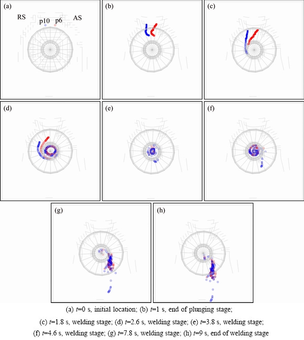
Fig. 13 Material flow patterns of particles p6 and p10 in different time
In addition, the material flow pattern is influenced by friction model such as shear model or coulomb model. In the models developed by TUTUNCHILAR et al [31] and PASHAZADEH et al [32] based on the constant shear friction model, the material on RS does not enter into the AS and eventually ends up in the RS rear of the tool, whereas in a model developed by YU et al [33] based on the CFD theory, the flow pattern of the RS material is similar to that presented in this work.
Previously, the material flow was experimentally examined by various tracer methods. COLLIGAN [34] investigated the material flow behaviors of 6061 and 7075 aluminum alloys during FSW using steel ball tracer technique and ��stop action�� technique. It was revealed that the location of the material relative to the pin determined its trajectory. REYNOLDS [35] studied the material flow behavior by means of a marker insert technique. It was concluded that upper and lower parts of the weld had different flow patterns. The current results are consistent with experimental observations. Thus, the ability of the present model to predict the material movement is well validated.
The flow patterns of horizontal points at the outside of the pin width on the AS and RS are shown in Fig. 14. It can be seen that the material flows on the RS and the AS are different. Some of material points on the RS do not enter into the AS with the increase of the distance from the stirring pin, as shown in Fig. 14(c). These material points on the RS far away from the pin directly flow to the rear of the weld but do not enter into the AS. Different from the tracer particle p22 on the RS, the material point p14 outside of the pin width with the same distance from the stirring pin on the AS can rotate with the pin and enter into the region under the shoulder on the AS. Compared with that in the location of particle p26, more materials enter into the stir zone near the pin at the location of particle p18.
From the above analyses, it can be seen that the relative location relationship between the tracer particles and pin can have significant effects on the material flow. In the horizontal direction, the stirring effect of the pin on the material flow behavior becomes weaker with the increase of distance from the pin. In the vertical direction, the material has a quite different flow patterns at the upper and lower parts of the weld. The material near the shoulder remains on the AS, and upon increasing the distance from the top surface, the material flows into the AS diminishes.
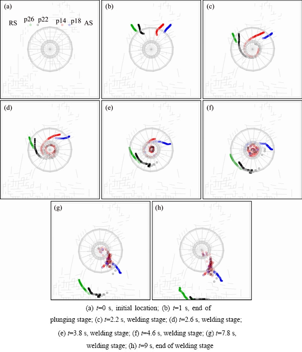
Fig. 14 Material flow patterns of particles p14, p18, p22 and p26 in different time
5 Conclusions
1) In front of pin, the material on the upper surface has the spiral downward movement affected by the shoulder whereas the lower material first moves in a spiral upward mode affected by the pin and then moves downward. These materials slough off on the AS after several rotations.
2) The variation of velocity and displacement of particles with time is obtained, and it can be used to estimate the rotation times.
3) The velocity of the tracer particles flowing at the periphery of the stirring pin is higher than that at the bottom of the weld.
4) At the outside of the pin width, the stirring effect of the pin on the material flow becomes weaker with the distance to the weld centerline. The material on the AS entered into the stir zone is slightly more than that on the RS at the same distance from the center of the pin.
References
[1] DAWOOD H I, MOHAMMED K S, RAHMAT A, UDAY M B. Effect of small tool pin profiles on microstructures and mechanical properties of 6061 aluminum alloy by friction stir welding[J]. Transactions of Nonferrous Metals Society of China, 2015, 25: 2856-2865.
[2] HE Zhen-bo, PENG Yong-yi, YIN Zhi-min, LEI Xue-feng. Comparison of FSW and TIG welded joints in Al-Mg-Mn-Sc-Zr alloy plates [J]. Transactions of Nonferrous Metals Society of China, 2011, 21: 1685-1691.
[3] KHAN N Z, KHAN Z A, SIDDIQUEE A N, AL-AHMARI A M, ABIDI M H. Analysis of defects in clean fabrication process of friction stir welding [J]. Transactions of Nonferrous Metals Society of China, 2017, 27: 1507-1516.
[4] MOGHADAM D G, FARHANGDOOST K. Influence of welding parameters on fracture toughness and fatigue crack growth rate in friction stir welded nugget of 2024-T351 aluminum alloy joints [J]. Transactions of Nonferrous Metals Society of China, 2016, 26: 2567-2585.
[5] MISHRA R S, MA Zong-yi. Friction stir welding and processing [J]. Materials Science & Engineering R, 2005, 50(1-2): 1-78.
[6] SHI Lei, WU Chuan-song. Transient model of heat transfer and material flow at different stages of friction stir welding process [J]. Journal of Manufacturing Processes, 2017, 25: 323-339.
[7] COLEGROVE P A, SHERCLIFF H R. CFD modelling of friction stir welding of thick plate 7449 aluminium alloy [J]. Science & Technology of Welding & Joining, 2013, 11(4): 429-441.
[8] COLEGROVE P A, SHERCLIFF H R. 3-Dimensional CFD modelling of flow round a threaded friction stir welding tool profile [J]. Journal of Materials Processing Technology, 2005, 169(2): 320-327.
[9] SEIDEL T U, REYNOLDS A P. Two-dimensional friction stir welding process model based on fluid mechanics [J]. Science & Technology of Welding & Joining, 2013, 8(8): 175-183.
[10] ULYSSE P. Three-dimensional modelling of the friction stir-welding process [J]. International Journal of Machine Tools & Manufacture, 2002, 42(14): 1549-1557.
[11] NANDAN R, ROY G G, LIERENT T J, DEBROY T. Numerical modeling of 3-D plastic flow of heat transfer during FSW of Stainless Steel [J]. Science & Technology of Welding & Joining, 2006, 11(5): 526-537(12).
[12] JI Shu-de, SHI Qing-yu, ZHANG Li-guo, ZOU Ai-li, GAO Shuang- sheng, LV Zan. Numerical simulation of material flow behavior of friction stir welding influenced by rotational tool geometry [J]. Computational Materials Science, 2012, 63: 218-226.
[13] HASAN A F, BENNETT C J, SHIPWAY P H. A numerical comparison of the flow behaviour in friction stir welding (FSW) using unworn and worn tool geometries [J]. Materials & Design, 2015, 87: 1037-1046.
[14] XU Shao-wen, DENG Xiao-min, REYNOLDS A P, SEIDEL T U. Finite element simulation of material flow in friction stir welding [J]. Science & Technology of Welding & Joining, 2001, 6(3): 191-193.
[15] DENG Xiao-min, XU Shao-wen. Two-dimensional finite element simulation of material flow in the friction stir welding process [J]. Journal of Manufacturing Processes, 2004, 6(2): 125-133.
[16] XU Shao-wen, DENG Xiao-min. A study of texture patterns in friction stir welds [J]. Acta Materialia, 2008, 56(6): 1326-1341.
[17] SCHMIDT H, HATTEL J. A local model for the thermomechanical conditions in friction stir welding modelling [J]. Modelling Simulation Materials Science Engineering, 2005, 13: 77-93.
[18] ZHANG Zhao, ZHANG Huang-wu. Numerical studies on controlling of process parameters in friction stir welding [J]. Journal of Materials Processing Technology, 2009, 209(1): 241-270.
[19] ZHANG Zhao, ZHANG Huang-wu. Numerical studies on the effect of transverse speed in friction stir welding [J]. Materials and Design, 2009, 30(3): 900-907.
[20] DIALAMI N, CERVERA M, CHIUMENTI M, de SARACIBAR C A. A fast and accurate two-stage strategy to evaluate the effect of the pin tool profile on metal flow, torque and forces in friction stir welding [J]. International Journal of Mechanical Sciences, 2017, 122: 215-227.
[21] DIALAMI N, CERVERA M, CHIUMENTI M, de SARACIBAR C A. Local�Cglobal strategy for the prediction of residual stresses in FSW processes [J]. International Journal of Advanced Manufacturing Technology, 2017, 88(9-12): 3099-3111.
[22] HAMILTON R, MACKENZIE D, LI H J. Multi-physics simulation of friction stir welding Process [J]. Eng Computations, 2010, 27(8): 967-985.
[23] ZHANG Zhao, ZHANG Huang-wu. A fully coupled thermo- mechanical model of friction stir welding [J]. International Journal of Advanced Manufacturing Technology, 2008, 37(3-4): 279-293.
[24] CUI Jun-hua, KE Li-ming, LIU Wen-long, GUO Zhen-hua, ZHAO Gang-yao, FANG Ping. Thermo-mechanical coupled finite element model for whole process of friction welding [J]. Journal of Material Engineering, 2014, 12: 11-17.
[25] ZHANG Zhao, CHEN Jin-tao. Computational investigations on reliable finite element-based thermomechanical-coupled simulations of friction stir welding [J]. International Journal of Advanced Manufacturing Technology, 2012, 60(9-12): 959-975.
[26] TANG W, GUO X, MCCLURE J C, MURR L E, NUNES A. Heat input and temperature distribution in friction stir welding [J]. Journal of Materials Processing Manufacturing Science [J]. 1998, 7(2): 163-172.
[27] MORISADA Y, FUJII H, KAWAHITO Y, NAKATA K, TANAKA M. Three-dimensional visualization of material flow during friction stir welding by two pairs of X-ray transmission systems [J]. Scripta Materialia, 2011, 65(12): 1085-1088.
[28] EDWARDS P D, RAMULU M. Material flow during friction stir welding of Ti-6Al-4V [J]. Journal of Materials Processing Technology, 2015, 218: 107-115.
[29] SU Hao, WU Chuan-song, BACHMANN M, RETHMEIE M. Numerical modeling for the effect of pin profiles on thermal and material flow characteristics in friction stir welding [J]. Materials & Design, 2015, 77: 114-125.
[30] LORRAINA O, FAVIERB V, ZAHROUNIC H, LAWRJANIECD D. Understanding the material flow path of friction stir welding process using unthreaded tools [J]. Journal of Materials Processing Technology, 2010, 210: 603-609.
[31] TUTUNCHILAR S, HAGHPANAHI M, BESHARATI G M K, ASADI P, BAHEMMAT P. Simulation of material flow in friction stir processing of a cast Al-Si alloy [J]. Materials and Design, 2012, 40: 415-426.
[32] PASHAZADEH H, TEIMOURNEZHAD J, MASOUMI A. Numerical investigation on the mechanical, thermal, metallurgical and material flow characteristics in friction stir welding of copper sheets with experimental verification [J]. Materials and Design, 2014, 55: 619-632.
[33] YU Zhen-zhen, ZHANG Wei, CHOO H, FENG Zhi-li. Transient heat and material flow modeling of friction stir processing of magnesium alloy using threaded tool [J]. Metallurgical and Materials Transactions A, 2012, 43: 724-737.
[34] COLLIGAN K. Material flow behavior during friction stir welding of aluminum [J]. Welding Journal, 1999, 78: 229s-237s.
[35] REYNOLDS A P. Visualisation of material flow in autogenous friction stir welds [J]. Science & Technology of Welding & Joining, 2000, 5(2): 120-124.
�߶�־1,2��������1��������2��������1
1. �й���ѧԺ �����о��� �������Ͽ�ѧ����(����)ʵ���ң����� 110016��
2. �������պ����ѧ ���Ͽ�ѧ�빤��ѧԺ������ 110136
ժ Ҫ�����ڹ�����ѧ���ۣ�����ABAQUS����Ԫ������������Ħ������(FSW)ȫ�����������ģ�ͣ������ʵ���ټ���ģ���о�FSWȫ���̲���������Ϊ�������������������Χ���ϵ��˶���ʽΪ�����˶��������ϲ����²����������Բ�ͬ��������ʽ���ϲ��ֲ���������Ӱ���»����������˶����²��ֲ����ڽ������Ӱ���»������˶�����������Χ�����ʵ�������ٶȸ��ڽ�����ײ��ʵ�ġ����Ͽ��ƽ�������ת���ܣ�ģ��������ʾ�����ӵ�ʵ��۲����� �Ǻϡ�
�ؼ��ʣ�����Ħ����������Ԫģ�⣻�ʵ���٣���������
(Edited by Xiang-qun LI)
Foundation item: Projects (51331008, 51405310, 51401219) supported by the National Natural Science Foundation of China
Corresponding author: Xing-xing ZHANG, Tel/Fax: +86-24-23971749, E-mail: xxzhang@imr.ac.cn; Zong-yi MA, Tel/Fax: +86-24-83978908, E-mail: zyma@imr.ac.cn
DOI: 10.1016/S1003-6326(18)64877-0

