
Dynamic simulation of universal spacer in Dynesys dynamic stabilization system for human vertebra
Sung-Min KIM1, In-Chul YANG2, Seung-Yeol LEE3, Sung-Youn CHO4
1. Department of Medical Bio Engineering, College of Biosystem, Dongguk University, Seoul, 100-715, Korea;
2. Research Institute of Biotechnology, Dongguk University, Seoul, 100-715, Korea;
3. Department of Advanced Technology Fusion, Graduate School, Konkuk University, Seoul, 143-701, Korea;
4. Research and Development Center, U&I Corporation, Uijungbu, 480-050, Korea
Received 2 March 2009; accepted 30 May 2009
Abstract: The aim of this study is to analyze the simulated behavior of universal spacer in Dynesys dynamic stabilization system inserted in human vertebra. Dynesys, so-called “Dynamic neutralization system for the spine”, dynamic stabilization system is a new concept in the surgical treatment of lower back pain recently. Universal spacer used as flexible material is to stabilize the spine and the material property of universal spacer is polycarbonate urethane. Universal spacer may apply different kinematic behaviors at implanted level in vertebra. Spinal range of motion(SROM) of inter-vertebra with installed Dynesys dynamic stabilization system was studied using Adams+LifeMOD as simulation software package. The vertebra model was set up to closely resemble the in-vivo conditions. Inter-vertebra rotations were measured by post processor of Adams and compared with the intact values. SROMs of the flexion, extension, lateral bending, and axial rotation of human virtual models were measured, where three spinal fixation systems such as rigid system, Dynesys system, and fused system were installed. As a result, the value of SROM is decreased in flexion-extension and lateral bending when the spinal fixation system is implanted. The movement of Dynesys system is similar to that of intact model by allowing the movement of lumbar. This means that the Dynesys system is proved to be safe and effective in the treatment of unstable spinal condition.
Key words: spinal fixation system; spine; spinal fusion; dynesys; lifeMOD
1 Introduction
Lumbar fusion supported by rigid instrumentation is often used in the treatment of a wide variety of spinal disorders. However, there are numerous clinical studies reporting accelerated disc degeneration adjacent to fused and/or rigidly instrumented segments. In order to maintain the mobility of a motion segment and to prevent negative effects on the adjacent segments, dynamic stabilization systems became more and more popular[1-3].
Dynesys, so-called “Dynamic neutralization system for the spine”, dynamic stabilization system is a new concept in the surgical treatment of lower back pain recently. STOLL et al[4] introduced the Dynesys (Dynamic neutralization system for the spine), and it was first used in France in 1994. Especially the Dynesys? (Zimmer Inc., Warsaw, IN, USA) system is the only posterior dynamic stabilization system to receive clearance from the US Food and Drug Administration (FDA) in 2004 and its clearance is granted only for use as an adjunct to fusion[5]. The Dynesys? system is composed of titanium alloy (Protasul 100) pedicle screws, polyethylene-terephalate (Sulene-PET) cords, and polycarbonat-urethane (Sulene-PCU) spacers (see Fig.1).

Fig.1 Dynesys spinal system on spine model (a) and CAD model (b)[6]
The objective of this study is to compare the kinematic behavior of spinal fixation systems that are Rigid system, Dynesys system, and Fused system to estimate the result after spinal fusion by virtual human model. Therefore, the spinal fixation system model was developed by commercial software (Adams, MSC Software, USA) for implant to the virtual human model.
BRG.LifeMOD 2005.5.0 (Biomechanics Research Group, Inc, USA) generates a standard skeletal model depending on the anthropometric variables (gender, height, mass, age and ethnicity). Spinal fixation system was installed from L4 to S1. The L4-S1 is represented as two motion segments of vertebra in patient. Four spinal fixation systems which are intact system, Rigid system, Dynesys system, and Fused system were developed. To simulate the human model motions which include flexion, extension, lateral bending, and axial rotation, four spinal fixation systems were installed to the lumbar vertebra between L4 and S1 with the aim of represent patient.
The simulation results are presented in terms of spinal range of motion (SROM). SROM is compared with the results of each system which are Rigid system, Fused system, Dynesys system to study the effect of spinal fixation system after spinal fusion. The advantages, disadvantages, and limitations of the method are presented and discussed.
2 Experimental
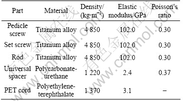
Dynesys system consists of spacer, cord, pedicle screw, and set screw as shown in Fig.1. Appropriate material properties were found from Refs.[7-9] as listed in Table 1.
Table 1 Material properties of stabilization device
In this study, pedicle screw and set screw were developed by commercial software which is Adams of MSC Software. Standard skeletal model depending on the anthropometric variables (gender, height, mass, age and ethnicity) was generated by BRG.LifeMOD 2005.5.0 (Biomechanics Research Group, Inc., USA) (see Fig.2). Spinal fixation system was installed from L4 to S1. L4-S1 is represented as two motion segments of vertebra in patient. Degeneration occurs very often at this point.

Fig.2 Skeletal full body models of human (a) and joints (b) at lumbar spine[10]
We developed three spinal fixation systems which are Rigid system, Dynesys system and Fused system. Intact model was created for the comparison with other system installed to human vertebra. Rigid system was fixed between L4 and S1 by pedicle screw and rigid rods. Dynesys system has dynamic stabilization device that includes pedicle screws and flexible rods instead of rigid rods. Fused system was a combine system which used rigid and flexible rods together at the inferior and superior segment. To simulate the human model motions which include flexion, extension, lateral bending, and axial rotation, four spinal fixation systems were installed to the lumbar vertebra between L4 and S1 with aim of represent patient. To represent the intervertebral disc dynamics, joint elements were created on the lumbar column from L4 to S1 (see Fig.2).
A soft tissue set which is ligament and muscle was generated from LifeMOD’s database of muscles. To compare with the result of each system, inverse dynamics simulation was performed to calculate the patterns of the muscle’s shortening and lengthening. In the forward dynamics simulation, each muscle tries to replicate the desired shortening/lengthening pattern obtained from the inverse dynamics simulation in order to reproduce the motion. As a result, we could compare with the range of motion(ROM) of each system which is Rigid system, Fused system, Dynesys system to study the effect of spinal fixation system after spinal fusion.
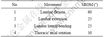
In this study, the motion data were obtained by spline to except the subjective motion. The range of motion of Intact model was established by spinal range of motion (SROM) which was indicated guideline of AMA (American Medical Association) (see Table 2). The motion data of human model using spline were calculated by displacement of head center of mass (CM) in X-axis, Y-axis, and Z-axis to represent the ROM of Intact model.
Table 2 Spinal range of motion of intact model[11]
3 Results
The simulation data of each motion were compared with the data of intact model in Table 2. The data of intact model were used for validation of human model before installed spinal fixation system. To obtain the SROM of intact model, lower body which is from the lumbar joint to the foot of human model was fixed to the ground. The upper body, from the lumbar joint to the head, motions were allowed. Through the diagram of Head CM (center of mass) position, the SROM was calculated by using trigonometry law. The SROM could be calculated by substitute for absolute value of displacement over Y-axis and Z-axis.
During the first 6 s, the displacement of flexion is presented, and from 6 s to 12 s the displacement of extension is presented in Fig.3.
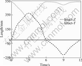
Fig.3 Diagram of head CM position in intact model at flexion and extension
3.1 Motion of flexion and extension
α1, SROM of the flexion motion, can be calculated and the displacements of a3 and b2 were obtained by the simulation results of each spinal fixation system which include Rigid system, Dynesys system and Fused system (see Fig.4). The method to get the α2 that is SROM of extension motion is also like the previous method at flexion. The SROM was calculated by the simulation results.
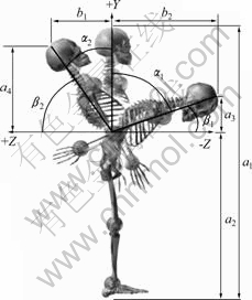
Fig.4 Range of motion of flexion/extension
By using trigonometry law, α1 can be expressed as
 (1)
(1)
a3 and b2 are obtained by the simulation as
 (2)
(2)
Thus, α1 is obtained as
 (3)
(3)
and
 (4)
(4)
a4 and b1 are obtained by the simulation as
 (5)
(5)
Thus, α2 is obtained as
 (6)
(6)
Therefore, if the displacements (a3, a4, b1 and b2) of the four models are known, α1 and α2 can be obtained.
As a result of flexion, the spinal range of motion of axial rotation was 60? in intact model, 26? in Rigid system, 41? in Fused system, and 55? in Dynesys system. The results mean that the SROM of Rigid system is decreased by 57% compared to that of the Intact model. The SROM of Fused system is decreased by 32% compared to that of the Intact model. The SROM of Dynesys system is decreased by 9% compared to that of the intact model. The SROM of Dynesys system is similar to that of the Intact model.
As a result of extension, the range of motion of axial rotation is 25? in intact model, 10? in Rigid system, 13? in Fused system, and 21? in Dynesys system. The results mean that the SROM of Rigid system is decreased by 60% compared to that of the intact model. The SROM of Fused system is decreased by 48% compared to that of the Intact model. The SROM of Dynesys system is similar to that of the Intact model. The difference of SROM is decreased by 16%.
3.2 Motion of axial rotation
Axial rotation is rotational motion of Y-axis over X-Z plane in LifeMOD coordinate system. The SROM of axial rotation motion was calculated by Eq.(7) and displacement of a and b was got by the simulation result of each spinal fixation system that includes Rigid system, Dynesys system and Fused system (Fig.5).
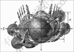
Fig. 5 Range of motion of axial rotation
α is obtained as
 (7)
(7)
Therefore, the spinal range of motion of the axial
rotation is 25? in intact model, 12? in Rigid system, 15? in Fused system, and 21? in Dynesys system. The results mean that the SROM of Rigid system is decreased by 52% compared to that of the Intact model. The SROM of Fused system is decreased by 40% compared to that of the Intact model. The SROM of Dynesys system is similar to that of the intact model. The difference of ROM is decreased by 16%.
3.3 Motion of lateral bending
Lateral bending is rotational motion of Z-axis over X-Y plane in LifeMOD coordinate system. The SROM of lateral bending motion was calculated by the displacement of angle (see Fig.6). The reference point of angle was Lumbar joint.

Fig.6 Range of motion of Lateral bending
The SROM (α) can be expressed as
 (8)
(8)
a1 and b are obtained by simulation
 (9)
(9)
Thus, α is obtained as
 (10)
(10)
Therefore, the spinal range of the motion of axial rotation is 30? in intact model, 10? in Rigid system, 18? in Fused system, and 23? in Dynesys system. The results mean that the SROM of Rigid system is decreased by 67% compared to that of the intact model. The SROM of Fused system is decreased by 40% compared to that of the intact model. The SROM of Dynesys system is similar to that of the intact model. The difference of SROM is decreased by 8%. All the simulation results of each system are shown in Table 3.
Table 3 SROM of each spinal fixation system
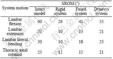
Fig.7 shows the performance ratio(PR) of each system. The performance ratio of each system was compared with that of the intact model. As can be seen from Fig.7 the performance ratio of Dynesys system is similar to that of the intact model. The performance ratio of Rigid system is almost 50% less than that of the Intact model. This means that the Rigid system limits the movement of lumbar after spinal surgery.

Fig.7 Performance ratio of each system compared with that of intact model
4 Conclusions
1) The simulation results about Rigid system, Fused system, and Dynesys system are in discord with result of Intact model. The results are similar to those of Dynesys system with Intact model. This verifies the SROM of Dynesys system is close to that of real motion. The range of motion of lumbar flexion is 60? in Intact model. The simulation result of SROM of Dynesys system is decreased by 9% compared to that of Intact model. In the lumbar extension and thoracic axial rotation, the simulation result of SROM of Dynesys system is decreased by 16% compared to that of Intact model. In the lumbar lateral bending, the simulation result of SROM of Dynesys system is decreased by 8% compared to that of Intact model. But, the huge increment of the SROM of Dynesys system will be caused by side effect that concentrates the stress to the adjacent vertebra which was implanted by Dynesys system. The possibility will not be able to attain a goal that is to reduce the back pain by spinal fixation system.
2) The results of this study proposed that the Fused system is the better system to minimize the side effect and complication until fused. Fused system will be help to maintain the operated vertebra for the stabilization.
3) For further study, to verify our results of simulation and proposal, clinical follow-up will be researched continuously about patients of spinal diseases. Using various virtual human model, the correlation between adjacent vertebra installed spinal fixation system will be analyzed.
References
[1] KUMAR M N, BAKLANOV A, CHOPIN D. Correlation between sagittal plane changes and adjacent segment degeneration following lumbar spine fusion [J]. Eur Spine J, 2001, 10(4): 314-319.
[2] LEE C K. Accelerated degeneration of the segment adjacent to a lumbar fusion [J]. Spine, 1988, 13(3): 375-377.
[3] LEHMANN T R, SPRATT K F, TOZZI J E, WEINSTEIN JN, REINARZ SJ, EL-KHOURY GY, COLBY H. Long-term follow-up of lower lumbar fusion patients [J]. Spine, 1987, 12(2): 97-104.
[4] STOLL T M, DUBOIS G, SCHWARZENBACH O. The dynamic neutralization system for the spine: a multi-center study of a novel non-fusion system [J]. Eur Spine J, 2002, 11: 170-178.
[5] JASON M. HIGHSMITH. Dynamic stabilization’s use in treating low back (lumbar) disorders [EB/OL]. http://www.spineuniverse.com, 2007.
[6] Korean medical library engine [EB/OL]. http://www.kmle.co.kr, 2008.
[7] SHIN D S, LEE K, KIM D. Biomechanical study of lumbar spine with dynamic stabilization device using finite element method [J]. Computer-Aided Design, 2007, 39: 559-567.
[8] EBERLEIN R, HOLZAPFEL G A, SCHULZE-BAUER C A J. Assessment of a spinal implant by means of advanced FE modeling of Intact human intervertebral discs[C]//Fifth World Congress on Computational Mechanics. Vienna: International Association for Computational Mechanics, 2002: 1-14.
[9] Wikipedia. Polycarbonate [EB/OL]. http://www.wikipedia.org, 2008.
[10] Biomechanics Research Group. Manual LifeMOD biomechanics modeler [M]. 2005.
[11] American Medical Association. Guides to the Evaluation of Permanent Impairment [R]. Bulletin No 239: 1990.
Corresponding author: Sung-Min Kim; Tel: +82-2-22697203; E-mail: smkim@dongguk.edu
(Edited by LONG Huai-zhong)

