Trans. Nonferrous Met. Soc. China 23(2013) 335-340
Microstructure and mechanical property of A356 based composite by friction stir processing
Don-Hyun CHOI1, Yong-Hwan KIM1, Byung-Wook AHN1, Yong-Il KIM2, Seung-Boo JUNG1,2
1. School of Advanced Materials Science and Engineering, Sungkyunkwan University, 300 Cheoncheon-dong, Jangan-gu, Suwon, Gyeonggi-do 440-746, Korea;
2. MEPL, Sungkyunkwan University, 300 Cheoncheon-dong, Jangan-gu, Suwon, Gyeonggi-do 440-746, Korea
Received 2 May 2012; accepted 9 October 2012
Abstract: Friction stir processing (FSP) was used to incorporate SiC particles into the matrix of A356 Al alloy to form composite material. Constant tool rotation speed of 1800 r/min and travel speed of 127 mm/min were used in this study. The base metal (BM) shows the hypoeutectic Al-Si dendrite structure. The microstructure of the stir zone (SZ) is very different from that of the BM. The eutectic Si and SiC particles are dispersed homogeneously in primary Al solid solution. The thermo-mechanically affected zone (TMAZ), where the original microstructure is greatly deformed, is characterized by dispersed eutectic Si and SiC particles aligned along the rotational direction of the tool. The hardness of the SZ shows higher value than that of the BM because some defects are remarkably reduced and the eutectic Si and SiC particles are dispersed over the SZ.
Key words: friction stir processing; A356 alloy; SiC powder; eutectic Si
1 Introduction
Cast A356 is one of the most widely used commercial Al�CSi�CMg alloys in the aircraft and automotive industries due to its good castability [1] and the fact that it can be strengthened by artificial aging [2-4]. However, the mechanical properties of A356 are significantly affected by microstructural features such as secondary dendrite arm spacing (SDAS) [5,6], microporosity [7,8], intermetallics [9], eutectic silicon particles [10,11], and heat treatments [2,12]. The as-cast microstructure of A356 is usually characterized by a coarse dendritic structure, nonuniformly distributed Si particles and porosity [5-8,13-16]. These micro- structural features limit the mechanical properties of cast alloys, in particular, in terms of toughness and fatigue resistance.
Metal matrix composites (MMC), where hard ceramic particles are distributed in a relatively ductile matrix, have widespread applications in aerospace, automobiles and other engineering industries because of their excellent physical, mechanical and tribological properties [17]. The electrolytic co-deposition of ceramic particles for fabrication of MMC coatings is attracting a lot of interest, as these coatings can be used in a large range of industrial applications, especially where high abrasive and protective properties are required [18].
LIM et al [19] found that the addition of SiC particles into the matrix of A356 Al alloy leads to an increase of wear resistance. GARCIA-CORDOVILLA et al [20] noticed that the wear resistance of AA6061/SiCp composites increases with an increase in the volume fraction and size of the reinforcements. It was proved that the hard ceramic particles increase the hardness and wear resistance of these composites.
Recently, much attention has been paid to friction stir processing (FSP) as a solid-state surface modification technique [21-23]. A rotating tool with a specially designed pin and shoulder is inserted into a substrate and rotates to produce a highly plastically deformed zone (stir zone). It is well known that the stir zone consists of fine and equiaxed grains produced by dynamic recrystallization [23]. FSP has also been used to fabricate surface composites. MISHRA et al [24] fabricated Al/SiCp surface composites by FSP, and showed that the added SiC particles were well distributed in the Al matrix, and a good bonding with the Al matrix was obtained.
Since the processing of surface composites during FSP is carried out at temperatures below the melting point of substrate, the problems in conventional techniques related to liquid phase processing at high temperatures can be avoided.
In this study, the composite of SiC reinforced A356 alloy is produced by FSP. The mechanical properties of the composite are evaluated and the microstructural changes are observed.
2 Experimental
The material used in this study was a piece of A356 Al alloy with dimensions of 140 mm��70 mm��4 mm. A356 Al alloy is a typical commercial hypoeutectic Al-Si alloy containing 7% Si, 0.25% Mg and a very small amount of the other additives. This material is commonly used for aircraft pump parts, automotive transmission cases, aircraft fitting and control parts, and water-cooled cylinder blocks. The FSW tool is made of hardened H-13 tool steel, which has a columnar shape with a shoulder and terminates in a threaded pin. The pitch distance was 1 mm. The tool rotation rate was set to be 1800 r/min, and its advancing speed was 127 mm/min.

Fig. 1 Schematic illustration of FSP process of A356 with SiC particles
To insert the particles, a groove with a depth of 1 mm and width of 2 mm was machined in cast A356 workpieces. A schematic illustration of the FSW setup is shown in Fig. 1. In order to prevent the sputtering of powders and their ejection from groove during processing, the groove��s gap was initially closed by aluminum tape. First, the back side was friction stir processed and then the front side was processed after the strip of aluminum tape was put in place. All FSW experiments were carried out at room temperature with a double pass (back side and front side).
The as-processed workpieces were cut in a direction transverse to the FSP direction, mechanically polished, and etched with Keller��s reagent (1 mL hydrofluoric acid, 1.5 mL hydrochloric acid, and 2.5 mL nitric acid in 95 mL distilled water). Microstructural observations were carried out at the cross sections perpendicular to the FSW direction by optical microscopy (OM) and scanning electron microscopy (SEM).
The Vickers hardness profile of the stir zone (SZ) was measured at the cross section and perpendicular to the processing direction using a Vickers indenter with a 0.98 N load for 10 s.
3 Results and discussion
Figure 2 shows the optical macro and microstructures near the SZ without SiC particles. The SZ appears as an ellipse and has an onion ring pattern that was formed by friction heat from the rotation of the tool and the forward movement extruding metal around the retreating side of the tool [25]. The flash is only released on the retreating side, where the direction of the tool rotation moves in the opposite direction to the travel direction (anti-parallel). Transition regions are formed between the SZ and unaffected BM. The dendrite microstructure of the BM is composed of a primary �� phase (white region) and an Al-Si eutectic structure (black region) (Fig. 2(b)). The primary �� phase occupies a much larger volume fraction than the Al-Si eutectic structure because the A356 alloy includes less Si contents than Al-Si eutectic point compositions with 12% Si in the Al matrix. The microstructure of the SZ is very different from that of the BM (Fig. 2(c)). The dendrite structure disappears and finer Si particles are dispersed over the whole SZ. There are no pores and the regularly distributed Si particles can be seen in the Al matrix. The SZ has a very homogeneous microstructure compared to that of the BM. The thermo-mechanical affected zones (TMAZ) are formed besides the SZ, which are divided into the retreating side (Fig. 2(d)) and the advancing side (Fig. 2(e)), and each zone displays different microstructures. The sharp transition between the BM and the SZ can be observed on the retreating side. A wider range of this deformed structure is observed on the advancing side, which has a more diffuse transient region.

Fig. 2 Macro cross-sectional image (a) and optical microstructures of FSPed A356 without SiC particles of BM (b), SZ (c), TMAZ (RS) (d) and TMAZ (AS) (e) zones marked in Fig. 2(a)
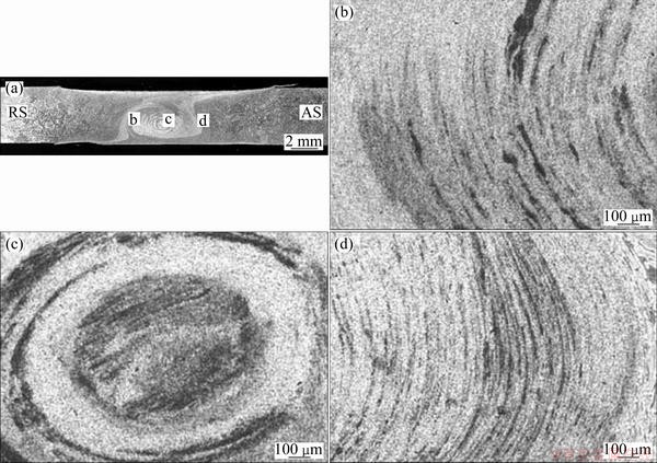
Fig. 3 Macro cross-sectional image (a) and optical microstructures of FSPed A356 with SiC particles of TMAZ (RS) (b), SZ (c) and TMAZ (AS) (d) zones marked in Fig. 3(a)
The optical macro and microstructures of the SZ with SiC particles are shown in Fig. 3. In spite of the groove which was placed in the workpieces, any cracks or defects are not observed in the SZ after FSP. The SZ shape is nearly the same as the SZ without SiC particles, but some black lines are observed in the SZ, which do not exist in the SZ without SiC particles (Fig. 3(c)). It is suggested that the black lines are related with the distribution of SiC particles. In the TMAZ, SiC particles are distributed along bands in the matrix (Figs. 3(b) and (d)). The high stresses and heat produced by the stirring tool are responsible for the material��s plastic deformation in this region, so that the agglomerated particles are stretched in the shear stress directions.
Figures 4 (a)-(c) show the SEM microstructures of the etched BM and SZ without SiC particles and SZ with SiC particles. In the BM, the plate-like and spherical Si particles are distributed partially in a primary �� phase and form a eutectic structure. However, the Si particles are homogeneously dispersed in the SZ and the plate-like particles are no longer present. This may be due to the plate-like Si particles being broken into slightly finer particles by the tool stirring. Also, the SZ with SiC particles is shown to be almost the same shape as the SZ without SiC particles, but more particles are observed in this region compared to the SZ without SiC particles. However, eutectic Si particles and SiC particles have almost the same shape and chemical composition. So Si and SiC particles could not be distinguished by the etched microstructure. The un-etched microstructures of each regions are shown in Figs. 4(d)-(f). No particles are observed in the BM and SZ without SiC particles, but many SiC particles are observed in the SZ with SiC particles. SiC particles are homogenously distributed in the SZ and the sizes of these particles are found to be 1-4 ��m. It seems that varying SiC particle size is related to the tool stirring where heavy deformations in the SZ cause the breaking of SiC particles.

Fig. 4 SEM microstructures of FSPed A356 with (a, b, c) and without etching (d, e, f)
The hardness profiles measured along the centerline of the cross section of the SZs with and without SiC particles are indicated in Fig. 5. The BM has a very wide range of hardness, from about HV 50 to 65. The BM has a hypoeutectic Al-Si microstructure. The Al solid solution, which is softer than the Si solid solution, occupies a large volume fraction. When the hardness indenter is located nearer the primary phase than near the eutectic Al-Si, the hardness is about HV 50, but as it moves toward the eutectic Al-Si, the hardness of the BM rises to over HV 60. The hardness of the BM depends on the point measured by the hardness indenter. However, the hardness of the SZ shows more uniform values than that of the BM due to the finer and more uniformly dispersed Si particles. The hardness of the SZ without SiC particles, which ranges from HV 60 to 65, is also uniformly distributed and shows less variation. In comparison, the SZ with SiC particles shows higher hardness values over a wider range from HV 60 to 85. This phenomenon may be due to suppression of GBS caused by the presence of SiC particles and grain size reduction.

Fig. 5 Distribution of Vickers hardness of FSPed A356 with and without SiC particles
4 Conclusions
1) The composite material of A356 with SiC particles was produced successfully by FSP.
2) In the SZ, the homogeneous distribution of SiC particles as well as the spherodization of Si needles and their spreading through the matrix are the dominant reasons for improvement of properties in the SZ.
3) The mechanical properties of the SZ with SiC particles, compared to the BM and SZ without SiC, were improved by the dispersed Si, SiC particles and the homogeneous microstructure.
Acknowledgments
This work was supported by a grant from the Fundamental R&D Program (No. 10038688) for Core Technology of Materials funded by the Ministry of Knowledge Economy, Republic of Korea.
References
[1] ZALENSAS D L. Aluminum casting technology [M]. 2nd ed. Illinois: AFS Inc, 1993: 77.
[2] ZHANG D L, ZHENG L. The quench sensitivity of cast Al-7 wt pct Si-0.4 wt pct Mg alloy [J]. Metallurgical and Materials Transactions A, 1996, 27: 3983-3991.
[3] DIN T, CAMPBELL J. High strength aerospace aluminum casting alloys: A comparative study [J]. Materials Science and Technology, 1996, 12: 644-650.
[4] YU Y B, SONG P Y, KIM S S, LEE J H. Possibility of improving tensile strength of semi-solid processed A356 alloy by a post heat treatment at an extremely high temperature [J]. Scripta Materialia, 1999, 41: 767-771.
[5] RADHAKRISHNA K, SESHAN S, SESHADRI M R. Dendrite arm spacing in alumium alloy castings [J]. Transactions of the American Foundry Society, 1980, 88: 695-702.
[6] OSWALY K J, MISRA M S. Dendrite arm spacing (DAS): A non destructive test to evaluate tensile properties of premium quality aluminum alloy (Al-Si-Mg) casting [J]. AFS International Cast Metals Journal, 1981, 6: 23-40.
[7] SURAPPA M K, BLANK E, JAQUET J C. Effect of macro-porosity on the strength and ductility of cast Al-7Si-0.3Mg alloy [J]. Scripta Materialia, 1980, 20: 1281-1286.
[8] CLOSSET B, GRUZLESKI J E. Structure and properties of hypoeutectic Al-Si-Mg alloys modified with pure strontium [J]. Metallurgical and Materials Transactions A, 1982, 13: 945-951.
[9] GUSTAFSSON G, THORVALDSSON T, DUNLOP G L. The Influence of Fe and Cr on the microstructure of cast Al-Si-Mg alloys [J]. Metallurgical and Materials Transactions A, 1986, 17: 45-52.
[10] CACERES C H, GRIFFITHS J R. Damage by the cracking of Si particles in an Al-7Si-0.4Mg casting alloy [J]. Acta Materialia, 1996, 44: 25-33.
[11] WANG Q G, CACERES C H. Fracture mode in Al-Si-Mg casting alloys [J]. Materials Science and Engineering A, 1998, 241: 72-82.
[12] CACERES C H, WANG Q G. Solidification conditions heat treatment and tensile ductility of Al-7Si-0.4Mg casting alloys [J]. Transactions of the American Foundry Society, 1996, 88: 1039-1043.
[13] KUMAI S, HU J, HIGO Y, NUNOMURA S. Effects of dendrite cell size and particle distribution on the near-threshold fatigue crack growth behavior of cast Al-SiCp composites [J]. Acta Materialia, 1996, 44: 2249-2257.
[14] ZHANG B, POIRIER D R, CHEN W. Microstructural effects on high-cycle fatigue crack initiation in A356.2 casting alloy [J]. Metallurgical and Materials Transactions A, 1999, 30: 2659-2666.
[15] SENIW M E, CONLEY J G, FINE M E. The effect of microscopic inclusion locations and silicon segregation on fatigue lifetimes of aluminum alloy A356 castings [J]. Materials Science and Engineering A, 2000, 285: 43-48.
[16] ATZAGA G, PELAYO A, IRISARRI A M. Effect of microstructure on fatigue behavior of cast Al-7Si-Mg alloy [J]. Materials Science and Technology, 2001, 17: 446-450.
[17] MANDAL D, DUTTA B K, PANIGRAHI S C. Wear properties of copper-coated short steel fiber reinforced stir cast Al-2Mg alloy composites [J]. Wear, 2008, 265: 930-939.
[18] LEKKA M, KOUMOULIS D, KOULOUMBI N, BONORA P L. Mechanical and anticorrosive properties of copper matrix micro- and nano-composite coatings [J]. Electrochemica Acta, 2009, 54: 2540-2546.
[19] LIM S C, GUPTA M, REN L, KWOK J K M. The tribological properties of Al�CCu/SiCp metal-matrix composites fabricated using the rheocasting technique [J]. Journal of Materials Processing Technology, 1999, 80-90: 591-596.
[20] GARCIA-CORDOVILLA C, NARCISO J, LOUIS E. Abrasive wear resistance of aluminium alloy/ceramic particulate composites [J]. Wear, 1996, 192: 170-177.
[21] MA Z Y, SHARMA S R, MISHRA R S. Microstructural modification of as-cast Al-Si-Mg alloy by friction stir processing [J]. Metallurgical and Materials Transactions A, 2006, 37: 3233-3236.
[22] SHARMA S R, MISHRA R S. Fatigue crack growth behavior of friction stir processed aluminium alloy [J]. Scripta Materialia, 2008, 59: 395-398.
[23] MISHRA R S, MA Z Y. Friction stir welding and processing [J]. Materials Science and Engineering R, 2005, 50: 1-78.
[24] MISHRA R S, MA Z Y, CHARIT I. Friction stir processing: A novel technique for fabrication of surface composite [J]. Materials Science and Engineering A, 2003, 341: 307-310.
[25] KRISHNAN K N. On the formation of onion rings in friction stir welds [J]. Materials Science and Engineering A, 2002, 327: 246-251.
����Ħ���ӹ��Ʊ�A356�������ϲ��ϵ�����֯����ѧ����
Don-Hyun CHOI1, Yong-Hwan KIM1, Byung-Wook AHN1, Yong-Il KIM2, Seung-Boo JUNG1,2
1. School of Advanced Materials Science and Engineering, Sungkyunkwan University, 300 Cheoncheon-dong, Jangan-gu, Suwon, Gyeonggi-do 440-746, Korea;
2. MEPL, Sungkyunkwan University, 300 Cheoncheon-dong, Jangan-gu, Suwon, Gyeonggi-do 440-746, Korea
ժ Ҫ��ͨ������Ħ���ӹ�������SiC�������뵽A356���Ͻ����Ʊ��������ϲ��ϣ�����Ħ���ӹ�����Ϊ����ת�ٶ�1800 r/min���н��ٶ�127 mm/min���������A356���Ͻ�Ϊ�ǹ���Al-Si֦����֯��������������֯������������ͬ������Si��SiC�������ȷֲ��ڳ�ʼ���������У��������˾��ұ��ε�����Ӱ�����Ĺ���Si��SiC����������ת�����ɢ����������������Ӳ�ȱȻ�������ĸߣ���Ϊ�ڽ��������ڵ�ȱ�����Լ��٣�����Si��SiC���ȷֲ������С�
�ؼ��ʣ�����Ħ���ӹ���A356�Ͻ�SiC��ĩ��������
(Edited by Sai-qian YUAN)
Corresponding author: Seung-Boo JUNG; Tel: +82-31-2907359; E-mail: sbjung@skku.edu
DOI: 10.1016/S1003-6326(13)62466-8

