辊速差对连铸连轧7075铝板显微组织、织构及力学性能的影响
来源期刊:中国有色金属学报(英文版)2021年第4期
论文作者:Mohammad Mehdi AMIRI Faramarz FERESHTEH-SANIEE
文章页码:901 - 912
关键词:连铸连轧;7075铝合金;辊速差;显微组织;力学性能;织构;各向异性
Key words:continuous casting and rolling; 7075 Al alloy; roll speed difference; microstructure; mechanical properties; texture; anisotropy
摘 要:研究辊速差对连铸连轧7075铝板显微组织、织构及力学性能的影响。采用3种不同上辊/下辊转速比(ω/ω0, ω为上辊转速,ω0为下辊转速)1:1、1:1.2及1:1.4进行多次试验。结果显示,在最大辊速差条件下(ω/ω0=1:1.4),7075铝板在轧制方向的屈服强度和极限抗拉强度分别提高41.5%和21.9%。此外,当辊速比ω/ω0为1:1.4时,成品轧制板的平均晶粒尺寸减小36%,横剖面平均硬度增加约9.2%。织构研究结果显示,辊速差越大,成品各向同性及硬度越大。然而,采用不同辊速度的连铸连轧会导致变形板伸长率降低约6%。
Abstract: The influences of the dissimilarity in the roll speeds on the microstructure, texture and mechanical properties of 7075 aluminum plates produced via combined continuous casting and rolling (CCCR) process were investigated. Several experiments were conducted with three different upper/lower roll rotational speed ratios (ω/ω0, ω is the upper roll rotational speed and ω0 is the lower roll rotational speed), namely 1:1, 1:1.2 and 1:1.4. It was found that the greatest dissimilarity in the roll speed (ω/ω0=1:1.4) improved the yield strength and ultimate tensile strength of 7075 Al plate in the rolling direction by 41.5% and 21.9%, respectively. Moreover, at a roll speed ratio of ω/ω0=1:1.4, the average grain size was decreased by 36% whereas the mean hardness of the transverse cross-section of the finally rolled plate was increased by about 9.2%. Texture studies also revealed that the more the difference in the roll speeds was, the greater the isotropy and the hardness of the final product were. Nevertheless, conducting CCCR operation with different roll speeds resulted in about 6% reduction in the elongation of the deformed plate.
Trans. Nonferrous Met. Soc. China 31(2021) 901-912
Mohammad Mehdi AMIRI, Faramarz FERESHTEH-SANIEE
Department of Mechanical Engineering, Faculty of Engineering, Bu-Ali Sina University, Hamedan 65178, Iran
Received 19 March 2020; accepted 1 December 2020
Abstract: The influences of the dissimilarity in the roll speeds on the microstructure, texture and mechanical properties of 7075 aluminum plates produced via combined continuous casting and rolling (CCCR) process were investigated. Several experiments were conducted with three different upper/lower roll rotational speed ratios (ω/ω0, ω is the upper roll rotational speed and ω0 is the lower roll rotational speed), namely 1:1, 1:1.2 and 1:1.4. It was found that the greatest dissimilarity in the roll speed (ω/ω0=1:1.4) improved the yield strength and ultimate tensile strength of 7075 Al plate in the rolling direction by 41.5% and 21.9%, respectively. Moreover, at a roll speed ratio of ω/ω0=1:1.4, the average grain size was decreased by 36% whereas the mean hardness of the transverse cross-section of the finally rolled plate was increased by about 9.2%. Texture studies also revealed that the more the difference in the roll speeds was, the greater the isotropy and the hardness of the final product were. Nevertheless, conducting CCCR operation with different roll speeds resulted in about 6% reduction in the elongation of the deformed plate.
Key words: continuous casting and rolling; 7075 Al alloy; roll speed difference; microstructure; mechanical properties; texture; anisotropy
1 Introduction
Having high strength and good corrosion resistance, 7000 series aluminum alloys are widely utilized in numerous applications, involving the transportation and aerospace industries [1-4]. That is why various investigations have been conducted to propose constitutive models and study the mechanical behavior of this series of the Al alloys [5,6].
Because of relatively high production rate, the rolling process is widely employed for producing many metallic plates and sheets. However, preparation of suitable ingots for this operation is very crucial [7]. With this regard, continuous casting suggests metallurgically improved quality, high manufacturing rate, significant energy saving and superior homogeneity for the billets to be deformed via the rolling process. Accordingly, several researches were carried out to manufacture products with controlled and high quality as well as enhanced mechanical properties through continuous casting process [1,8-12].
Flat rolling is a commonly employed operation for making 7075 Al alloys due to its potential for mass production. This process could be carried out at room temperature as well as elevated temperatures, depending on the size, material and type of the initial workpiece [7]. When the necessary forming force and energy should be reduced and the ductility of the material must be enhanced, hot rolling is used [7]. Nevertheless, significant energy and efforts should be made for increasing the temperature of the slab to the target one. In hot rolling, when the initial slab is produced via continuous casting, the required cost and energy decrease meaningfully [2]. Using this advantage in conjunction with difference in the roll speeds (i.e. asymmetric rolling) could intensify the improvements in mechanical behavior of the final product.
POLKOWSKI et al [13] carried out asymmetric rolling of an Al-Ni alloy in order to study the effects of the operation on the texture and microstructural evolution of the workpiece. Based on the mechanical testing and EBSD images, they found that the process intensified the anisotropy behavior of the rolled sheet. LOORENTZ and KO [14] investigated the influence of asymmetric rolling on the mechanical properties and microstructure of 5052 Al alloy. After employing the operation four times, the average grain size considerably decreased and, consequently, the ultimate tensile strength (UTS) of the material increased significantly. YANG et al [15] studied the details of deformation of Al-Mg-Si alloy during the asymmetric rolling process. They claimed that the difference in the roll speeds could enhance the mechanical properties, especially the UTS of the deformed sheets. Several researchers [16-18] also focused their work on the effects of rolling parameters on the final rolled 7075 Al sheets and plates. Several others [19,20] concentrated on the mechanisms of texture evolution and their influences on the properties of asymmetric rolling products. With this regard, REN et al [19] claimed that compared with annealed symmetrically rolled AA6016 sheets, the shear texture ({111}//ND) of the annealed asymmetrically rolled sheet was enhanced during nucleation and grain growth due to recrystallization whereas the cube texture was weakened, resulting in a distinct growth in the Lankford coefficient for the latter sheet. REN et al [20] also investigated the shear texture evolution of a twin-roll casting AA6016 sheet with an original R-cube and E textures through asymmetric rolling. They found that the initial R-cube texture changed to Dillamore/Copper texture with the growth in the induced strain, while the initial E texture was weakened, resulting in an improvement in the F texture through asymmetric rolling operation.
None of the above-mentioned researches involved the influence of combined continuous casting and rolling (CCCR) operation on the mechanical properties of finally rolled 7075 Al alloy. The present research work was concerned with simultaneous continuous casting and rolling process of this alloy. With this regard, the influences of difference in the roll speeds on the microstructure, texture and mechanical properties of the rolled plates were investigated.
2 Experimental
As illustrated in Fig. 1, the cauldron (pot), cooling jacket and rolling stand are the central modules of the designed and constructed CCCR machine. Several important dimensions and positions of the thermocouples used for assessing the temperature at different stages are also shown in this schematic figure. The pot was made of SS 308 stainless steel and equipped with a gate at its bottom. The cooling jacket, having a length of 230 mm, was also made of SS 308 stainless steel to avoid corrosion and oxidation. This unit was equipped with a couple of heaters and a cooling duct for providing appropriate temperature reduction, namely linear from the entrance to the exit of the cooling jacket [21]. At the start of the process, the heaters were employed for preheating the cooling jacket to 690 °C. After preparation of the molten alloy, the vertical gate was opened and the melt entered the cooling jacket.
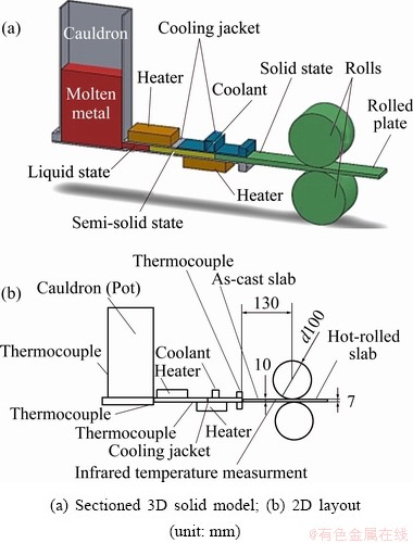
Fig. 1 Representative diagrams of simultaneous continuous casting and rolling device for making 7075 Al plates
The solidified alloy departed the jacket at a temperature of about 450 °C and after passing a distance of 130 mm, under exposure to the surrounding air, moved into the roll gap at a temperature of 425 °C. The hot slab was subjected to 30% reduction in thickness by means of a couple of rolls with the same diameters of 100 mm and made of VCN 200 alloy steel, each was powered by a separate 1.1 kW electrical motor. The roll speeds were adjusted to provide sufficient time for solidification of the molten alloy in the cooling jacket and to avoid formation of possible internal cracks in the 7075 Al slab.
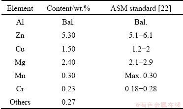
Several K thermocouples (ABB model) were mounted at different positions for measuring the temperature of the melted alloy in the pot and cooling jacket. An infrared temperature measuring apparatus was also used to assess the slab temperature at the entry of the roll gap. After start of the rolling operation, the CCCR process was progressively continued until the free surface of the molten alloy reached about 10 mm above the exit of the pot. This remedy ensured complete filling of the cooling jacket during the CCCR process. The composition of the finally produced 7075 Al plates is summarized in Table 1.
Table 1 Composition of 7075 Al alloy used for CCCR experimental studies
In order to investigate the roll speed difference on the properties of the final product, the rotational speed of the lower roll was kept constant, namely 1 r/min. Afterwards, during various CCCR experiments, the upper roll speed/lower roll rotational speed ratio (ω/ω0, ω is the upper roll rotational speed, and ω0 is the lower roll rotational speed) was adjusted to be 1:1, 1:1.2 and 1:1.4, respectively. Each test was continued until 7075 Al plate with desired length was manufactured. To prevent any change in the microstructure of the final product, the plate was immediately cooled after the rolling process using appropriate water spray. To conduct microstructural studies, after preparation of samples from different CCCR tests, they were polished using various sand papers, respectively with 400, 800, 1000 and 2000 grades. Subsequently, these specimens were etched by employing Polton solution (4 mL H2O + 1 mL HF (48%) + 6 mL HNO3). The micrographs were obtained by means of an optical microscope. Finally, employing MIP software and the linear intercept method and taking the average value of 50 horizontal and 50 vertical lines, the average grain size (AGS) for each sample was measured. The type and number of lines were selected to minimize the influence of dendrites on the accuracy of AGS obtained from the software.
In the present investigation, the cylindrical compression test under dry friction condition was employed for gaining the flow curves in the rolling direction (RD), transverse direction (TD) and normal direction (ND) of the 7075 Al plates produced via CCCR operation. The initial diameter and height of the cylindrical samples were 5 and 7 mm, respectively. The compression experiments were accomplished with a 400 kN servo-electrical testing apparatus with an average strain rate of 0.0001 s-1 at room temperature.
To conduct a profound study about anisotropy of the plates deformed with different roll speed ratios, the pole figures and inverse pole figures of various CCCR specimens were obtained. By employing a Rigaku ultimate IV X-ray diffracto- meter apparatus, the textures of different samples were examined to interpret the results obtained from the hardness and compression tests. The rolling direction of the specimen was directed to the experimenter and the orientation normal to the slab was set to the north pole. The structure of Al alloys is FCC. Hence, the (111) and (200) planes respectively demonstrate the most diffraction of the X-ray. Hence, incomplete pole figures for these planes were gained, and to calculate the complete pole figures, TexTools software was used.
3 Results and discussion
3.1 Microstructural observations
Friction is an inseparable phenomenon of any rolling process. In a traditional rolling process both rolls operate with the same nominal rotational speed, besides the normal pressure, a shearing frictional stress is also applied by each roll onto the deformed slab. Since both the rolls rotate with an identical velocity, it can be assumed that the middle horizontal surface of the workpiece is not affected by the shearing stress, although it is influenced by the normal interfacial pressure [7]. Therefore, the shearing frictional stress varies from a maximum value in the roll-slab contact area to zero on the middle surface. In this situation, the neutral plane (where the direction of the frictional forces changes) is parallel to the line connecting the centers of the rolls. However, when the rolls rotate with different speeds, the neutral plane is inclined and makes an angle with the vertical centerline of the rolls. The larger the difference between the roll speeds is, the greater this angle is. This inclination of the neutral plane implies that, besides the frictional forces of conventional rolling process, the material is subjected to an additional severe shearing stress. This excessive shearing stress induces large shearing strains into various elements of the material such that it could be said that the workpiece is subjected to a severe plastic deformation. When a material experiences a severe plastic deformation, its grain size is reduced significantly [23,24].
Figure 2 illustrates how the roll speed dissimilarities have affected the microstructure of the samples subjected to CCCR operation. The location where the micrographs were taken, was actually in the vicinity of the center of transverse cross-section of the rolled slab, i.e. around mid-width and mid-thickness of the rolled slab. The average grain size (AGS) calculated for each process condition is shown in Fig. 3. Based on the results presented in both figures, the conventional rolling process caused about 16.1% reduction in the AGS in comparison with the as-cast 7075 Al alloy. But roll speed differences of 20% and 40% have resulted in much greater decrease in the average grain size of the as-cast slab, namely 32.5% and 46.2%, respectively. As stated previously, this greater grain refinement is mainly due to larger severe shear deformations in the case of CCCR process with higher roll speed dissimilarities. More or less, this observation is in agreement with those made for previous researches regarding other alloys and materials [25-28]. LUO et al [25] conducted asymmetric rolling on AZ31 Mg alloy at 350 °C. They reported a reduction in AGS for a roll speed ratio (ω/ω0) of 1:1.2 and claimed greater decrease in grain size for larger values of roll speed differences. They calculated average grain sizes of 11.8, 11.2 and 10.3 μm for roll speed ratios of 1:1, 1:1.2 and 1:1.3, respectively. HAMAD and KO [27] also employed the asymmetric rolling process for a carbon steel at room temperature. In their work, performing four passes of the operation with a roll speed ratio of 1:1.4 significantly influenced the reduction in AGS which decreased to less than 1 μm.
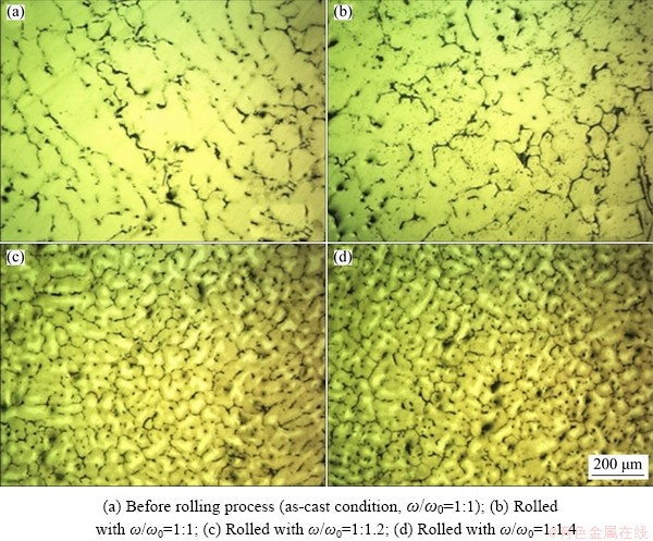
Fig. 2 Microstructures of various 7075 Al samples
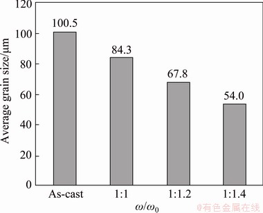
Fig. 3 Effect of roll speed ratio (ω/ω0) on average grain size of 7075 Al alloy
BINTO et al [28] investigated the behavior of 5183 Al alloy subjected to symmetric and asymmetric rolling followed by a heat treatment. They found that the asymmetric rolling process, particularly that including 4 passes, could improve the grain refinement and mechanical properties, but the strain rate sensitivity of the alloy did not change.
In a hot asymmetric rolling, since the material moving through the roll gap is subjected to severe shear strains due to roll speed dissimilarity, various slip mechanisms are active in crystals with different orientations. Therefore, the dislocations move inside the grains until they arrive at the grain boundaries. By gathering the dislocations around the grain boundaries, the energy in these areas increased, resulting in the formation of new grains [29]. This phenomenon, which is shown in Fig. 4, finally reduced the AGS of the alloy and improved its mechanical properties [30].
Another mechanism of creation of new grains in situations where the deformation was less than 40% and the forming process was carried out in hot conditions was stated by RIOSTA et al [31]. They claimed that under the above-mentioned conditions (which almost conform to experimental conditions in CCCR practical tests), the mechanism of recrystallization start could be “strain-induced grain boundary migration”. This mechanism takes into account the migration of a pre-existing grain boundary towards the inside of a more highly strained grain. The required condition for this process to take place is the favorable energy- balance between the decrease of stored energy due to the removal of defects caused by the passage of the boundary and the increase in total grain boundary surface due to bulging [31]. In such situations, nucleation occurs between two large adjacent grains. In Fig. 4, since the marked small grain is surrounded by several large grains, and based on the amount of strain induced during the rolling stage of the CCCR operation and level of the processing temperature, one can suppose that this new grain was created by the nucleation mechanism explained above.
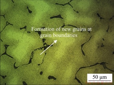
Fig. 4 New grain formation due to dislocation immigration towards grain boundaries in sample rolled with ω0/ω=1:1.4
3.2 Strength, ductility and texture
To determine the ductility of a material, various methods can be employed for obtaining its stress-strain curves. In this research, the cylindrical compression test under intermediate friction condition (the bulge correction factor method [32]) was used for deriving the flow curves in the RD, TD and ND of the rolled 7075 Al plate. In this technique, based on the barreled shape of the deformed test sample, a correction factor was calculated and applied to the experimental results in order to eliminate the effect of interfacial friction on the flow stress [32]. Using the offset method and drawing a straight line at a strain of 0.002 and parallel to the initial linear part of each stress-strain curve, the yield strength of the corresponding sample was derived. The initial diameter and height of cylindrical specimens were 5 and 7 mm, respectively. The compression tests were conducted with a 400 kN servo-electrical testing machine. The flow curves obtained by means of the above-mentioned method are plotted in Fig. 5. The experimental findings shown in this figure imply that certain anisotropy behavior is induced in almost all the plates rolled under different conditions. Moreover, by creation and increase in the roll speed difference, the final product represents higher strength and lower ductility.

Fig. 5 True stress-strain curves obtained from CCCR plates produced at various roll speed ratios in different directions
In order to carry out a deep study regarding the anisotropy level of the plates manufactured with various roll speed ratios, the pole figures and inverse pole figures of different CCCR samples were prepared. Performing mechanical work on the metals and alloys changes the orientations of the grains. When a greater number of grains are arranged in a particular direction, a more intensive wave will received by the X-ray diffraction apparatus [33]. In pole figures, each group of grains having a common normal vector corresponding to a specific plane, make up a pole in a circular diagram. The vertical diameter of this circle is parallel to the rolling direction, whereas its horizontal axis is in the transverse direction. In a pole figure, where the intensity and concentration of the contours are higher, more grains are oriented in that specific direction. Hence, the texture intensity factor of a pole figure is an indication of the level of anisotropy of a rolled plate [34,35].
As can be observed in Fig. 6, among various 7075 Al plates produced via the CCCR process, the specimen rolled with 1:1 speed ratio represents the maximum intensity, namely 5.5 and 7.1 for {111} and {200} planes, respectively. These values reduce to 2.5 and 3.1 for 1:1.2; and 2.0 and 2.8 for 1:1.4 speed ratios, respectively. Therefore, one can conclude that the product rolled conventionally possesses higher anisotropy compared with those manufactured with roll speed differences. This point can be verified by results illustrated in Fig. 7, where the yield strength (YS), ultimate tensile strength (UTS) and fracture strain (FS) of all the samples produced under various process conditions are plotted. As can be seen in this figure, the difference between ultimate tensile strengths in RD and ND for conventionally rolled specimen is 62 MPa. This value becomes lower by increasing the roll speed dissimilarity, namely 29 and 14 MPa for speed ratios of 1:1.2 and 1:1.4, respectively. It is also worthy to mention that, based on the microstructural studies, the larger the roll speed difference, the lower the AGS of the finally produced plate. Since grain boundaries act as barriers against the movement of dislocations, the greater velocity dissimilarities have eventually resulted in higher yield strength and ultimate tensile strength in the relevant samples, as can be observed in Fig. 7. Moreover, it is claimed that the mechanical working during a rolling process could cause the inclusions to be directed and elongated in the RD [36]. It seems that this is the case when dissimilarity in the rotational speeds of the rolls exists because going through Fig. 7, one can find that both the yield strength and ultimate tensile strength in the TD and ND are lower than the corresponding values in the RD except the yield strength at a roll speed ratio of 1:1.2.

Fig. 6 Pole figures for a couple of crystal planes at three different roll speed ratios
The lower anisotropy of 7075 Al alloy subjected to CCCR operation with different roll velocities, in comparison with that of the plate produced via the process with the same roll speeds, can also be proved by means of the inverse pole figures of various samples (Fig. 8). Among various atomic directions, {110} direction is the densest one due to the particular arrangement of atoms in an FCC crystal structure. In other words, in this direction the atoms are closer to each other and the atomic bonding energy is considerably higher [33]. Therefore, it can be concluded that when the texture of the specimen is such that the {110} direction is aligned to the axis of the compression test cylinder, an upper ultimate tensile strength could be attained in the experiment. Consequently, the changes in the ultimate tensile strength in Fig. 7 can be understood by reviewing Fig. 8.

Fig. 7 Mechanical properties of 7075 Al alloy processed via CCCR process with various roll speed ratios in different directions
Using the “densitometer” tool of the “Text Tools” software, {110} texture intensities in the RD and ND for the traditionally rolled Al alloy were 3.7 and 0.7, respectively. These values have correspondingly changed to 1.4 and 0.9 for 1:1.2 roll speed ratio; and to 1.3 and 1.1 for 1:1.4. Hence, on one hand, for all the specimens manufactured under various process conditions, the ultimate tensile strength in the RD should be higher than that in the ND. On the other hand, the difference in the strengths of these two directions will decrease when dissimilarity in the roll speed increases. In other words, based on the inverse pole figures, the plates asymmetrically rolled via CCCR operation represent higher isotropy and similarity in material properties in different directions. The greater the roll speed difference, the larger the induced shear strain during the hot asymmetric rolling. Consequently, AGS decreases, which means the creation of a larger number of grains. When the number of recrystallized grains increases, statistically speaking, their crystallographic slip planes could be arranged more randomly in various directions. By this means, the deformed part represents almost the same mechanical properties in different directions, which implies a more isotropic behavior. Both the mechanical testing in RD, TD and ND and the above-mentioned texture studies confirm this reasoning.
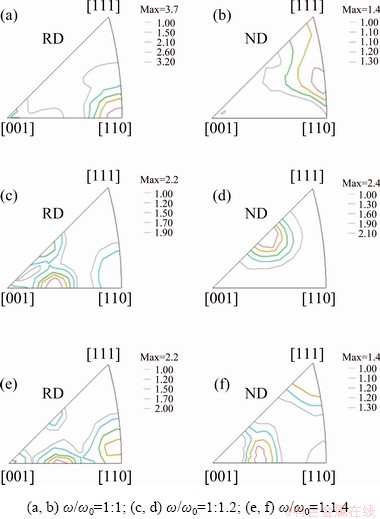
Fig. 8 Inverse pole figures in rolling and normal directions for 7075 plates rolled at various speed ratios
The {111} plane in an FCC crystal structure, such as aluminum, is the major slip plane for plastic deformation of the alloy. Therefore, when this plane for most of the grains is aligned parallel to the plate surface, the slab can experience relatively high plastic deformations [33]. Hence, in pole figures of {111} plane, where the maximum texture intensity is higher, the relevant sample should represent greater ductility. In Fig. 6, the maximum intensity for {111} plane, namely 5.5, belongs to the sample rolled traditionally and, consequently, this product should exhibit the greatest formability. Going through stress-strain curves shown in Fig. 5 and experimental findings summarized in Fig. 7, one can realize that the cylindrical specimens of the plate rolled with 1:1 speed ratio demonstrate the maximum reduction in height in RD, TD and ND, in comparison with those processed with roll speed dissimilarity.
As stated above and based on Figs. 5 and 7, the ductility of the material decreases by creating and increasing the roll speed difference in the rolling stage of a CCCR process. This can be interpreted by remembering that at the grain boundaries, there is a greater chaos and entropy and this, consequently, decreases the bonding energy of atoms located in these areas. For a higher roll speed ratio, the grain size is reduced and, hence, the grain boundaries are enlarged. Therefore, when the grain boundary slip occurs, the probability of crack occurrence at the grain boundaries will increase and, finally, the cylindrical compression test sample will be fractured at a lower true strain.
3.3 Distribution of hardness
The hardness of CCCR component was measured on its transverse cross-section, at various points of three levels, namely top, middle and bottom surfaces of the deformed part. Figure 9 illustrates these findings. First of all, it is clear from this figure that for all the top, middle and bottom surfaces of the CCCR product, the greater the difference in the roll speed, the larger the hardness of the material. This is mainly due to significant shear strains induced into the alloy when dissimilarity in the roll velocities takes place. For all the roll speed ratios, the hardness of the middle surface is lower than that of the other ones because despite the upper and lower surfaces of the slab, its middle plane is less affected by the heat transfer to the surrounding air and forming rolls. Moreover, the frictional engagement of the slab and rolls can result in a greater effective strain on the top and bottom surfaces, in comparison with the middle surface. Consequently, this can cause more grain refinements and larger values for the hardness at upper and lower surfaces of the deformed parts. These findings are in agreement with the previous observations for the CCCR operation [21]. More apparent change in the experimental results for middle surface of the components rolled with 1:1.2 and 1:1.4 speed ratios implies that the influence of heat transfer overwhelmed the induction of shear strains at the roll-workpiece interfaces.
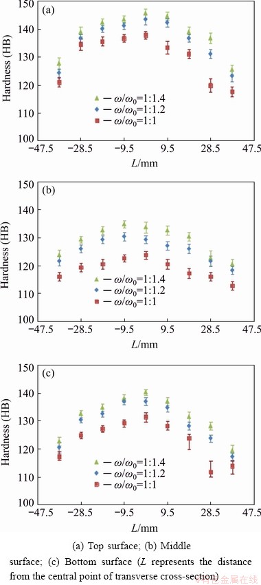
Fig. 9 Variations of Brinell hardness along TD of CCCR samples at different roll speed ratios and various locations through thickness
Another important observation in Fig. 9 is the lower hardness of the edges of the plate subjected to CCCR process, compared with its center. AMIRI and FERESHTEH-SANIEE [21] claimed that at the center of the transverse cross-section of the slab, a plane-strain state of deformation existed which could provide a severe restriction for transverse flow of metal. This, in turn, created a greater mechanical work at the center of the workpiece compared with the adjacent regions. Because of higher strains induced, larger strength and hardness should be observed in the central region of the rolled specimen. To ensure this reasoning, the micrographs of three different areas of the transverse cross-section were obtained at a roll speed ratio of 1:1.4, shown in Fig. 10. These locations were the central point of the cross-section together with two points on the left and right sides, each 28.5 mm apart from the center.
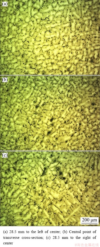
Fig. 10 Micrographs of 7075 Al alloy subjected to CCCR operation through thickness at roll speed ratio of 1:1.4
As is clear from Fig. 10, the average grain size of the central region is considerably lower than that of the left and right points. Therefore, based on the Hall-Petch relation, we should expect higher hardness and strength for the center of cross-section, compared with its adjacent regions. The AGS values measured for the central, left and right areas of the cross-section were 54.0, 60.0 and 63.1 μm, respectively. On the other hand, the average values of hardness measured for the central, left and right points were 134.8 HB, 128.1 HB and 122.6 HB, respectively, obeying the Hall-Petch relationship. Keeping in mind that the homologous temperature of the CCCR operation (T/Tm) was about 0.78 (greater than 0.5), the dynamic recrystallization (DRX) accompanied with the plastic working and the induction of strains into the material. Since these plastic deformations were not the same across the transverse cross-section, variation in hardness explained above occurred.
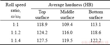
Observing the experimental results illustrated in Fig. 9, one can find out that there is a slight variation in the hardness through the thickness of the rolled slab. This is mainly due to difference in heat convection conditions on the upper and lower surfaces of the workpiece during 130 mm traveling between the cooling jacket and roll gap (see Fig. 1). Finally, Table 2 shows the average hardness of the transverse cross-section for various thickness locations and roll speed ratios. Based on the findings summarized in this table, increasing the roll speed ratio from 1:1 to 1:1.2 and 1:1.4 has resulted in hardness improvement by 6.0% and 9.2%, respectively, for the middle surface. These values are 4.4% and 7.2% for the top surface, and 4.9% and 8.0% for the bottom surface of the specimen, implying that the effect of roll speed difference is more observable for the middle plane compared with the upper and lower surfaces of the rolled part.
Table 2 Average values of Brinell hardness for different roll speed ratios and various thickness positions
4 Conclusions
(1) The greater the roll speed difference was, the larger the reduction in the grain size of the product was. A dissimilarity of 40% in the rotational velocities of the rolls resulted in about 36% reduction in the average grain size of 7075 Al alloy, in comparison with traditional rolling.
(2) The roll speed dissimilarity shaped a more isotropic plate. This was verified using the pole figures and inverse pole figures of various CCCR specimens. The difference of strengths in TD and ND of a traditionally rolled 7075 Al plate was 8.2%, whereas this value was 2.8% for a roll speed ratio of 1:1.4 in CCCR process.
(3) A larger roll speed ratio caused greater increase in the yield strength and ultimate tensile strength and greater reduction in the ductility of the finally rolled 7075 Al plate. Quantitatively, 40% dissimilarity in roll speeds resulted in 41.5% and 21.9% improvements in the yield strength and ultimate tensile strength in the rolling direction, respectively, whereas the fracture strain for this direction was reduced by 68.3%.
(4) A roll speed ratio of 1:1.4 created about 14% difference in the average grain size in the transverse direction. This was mainly attributed to dissimilarity in the flow regimes of the center and the edges of the slab during the asymmetric rolling process. This conclusion was also confirmed by hardness measurements on the transverse cross- section of the rolled plate.
References
[1] SU X, XU G M, JIANG D H. Abatement of segregation with the electro and static magnetic field during twin-roll casting of 7075 alloy sheet [J]. Materials Science and Engineering A, 2014, 599: 279-285.
[2] CHEN S D, CHEN J C. Simulation of microstructures in solidification of aluminum twin-roll casting [J]. Transactions of Nonferrous Metals Society of China, 2012, 22: 1452-1456.
[3] WANG S H, MENG L G, YANG S J, FANG C F, HAO H, DAI S L, ZHANG X G. Microstructure of Al-Zn-Mg-Cu- Zr-0.5Er alloy under as-cast and homogenization conditions [J]. Transactions of Nonferrous Metals Society of China, 2011, 21: 1449-1454.
[4] CHEGINI M, SHAERI M H. Effect of equal channel angular pressing on the mechanical and tribological behavior of Al-Zn-Mg-Cu alloy [J]. Materials Characterization, 2018, 140: 147-161.
[5] PENG L M, MAO X M, XU K D. Simulation and control model for interactions among process parameters of directional solidification continuous casting [J]. Transactions of Nonferrous Metals Society of China, 2000, 10: 449-452.
[6] CHEN G, REN C Z, KE Z H, LI J, YANG X P. Modeling of flow behavior for 7050 -T7451 aluminum alloy considering microstructural evolution over a wide range of strain rates [J]. Mechanics of Materials, 2016, 95: 146-157.
[7] MOSHKSAR M M. Rolling principles [M]. Shiraz, Iran: Shiraz University Press, 2012.
[8] WU L, KANG H J, CHEN Z N, LIU N, WANG T M. Horizontal continuous casting process under electromagnetic field for preparing AA3003/AA4045 clad composite hollow billets [J]. Transactions of Nonferrous Metals Society of China, 2015, 25: 2675-2685.
[9] WANG G S, ZHAO Z H, CUI J Z. The magnetic field interference in dual-ingot low frequency electromagnetic continuous casting [J]. Advanced Materials Research, 2013, 821: 868-872.
[10] ZHANG H T, CUI J Z. Production of super-high strength aluminum alloy billets by low frequency electromagnetic casting [J]. Transactions of Nonferrous Metals Society of China, 2011, 21: 2134-2139.
[11] QU F, CUI J Z. Effect of magnetic field on air film continuous casting [J]. Advanced Materials Research, 2011, 189: 2827-2831.
[12] LI D F, ZHANG D Z, LIU S D, SHAN Z J, ZHANG X M, WANG Q, HAN S Q. Dynamic recrystallization behavior of 7085 aluminum alloy during hot deformation [J]. Transactions of Nonferrous Metals Society of China, 2016, 26: 1491-1497.
[13] POLKOWSKI W, PECZEK E, ZASADA D, KOMOREK Z. Differential speed rolling of Ni3Al based intermetallic alloy―Effect of applied processing on structure and mechanical properties anisotropy [J]. Materials Science and Engineering A, 2015, 647: 170-183.
[14] LOORENTZ, KO Y G. Effect of differential speed rolling strain on microstructure and mechanical properties of nanostructured 5052 Al alloy [J]. Journal of Alloys and Compounds, 2014, 586: 205-209.
[15] YANG H W, WIDIANTARA I P, KO Y G. Effect of deformation path on texture and tension properties of submicrocrystalline Al-Mg-Si alloy fabricated by differential speed rolling [J]. Materials Letters, 2018, 213: 54-57.
[16] ZHANG T, WU Y X, GONG H, ZHENG X Z, JIANG S S. Effects of rolling parameters of snake hot rolling on strain distribution of aluminum alloy 7075 [J]. Transactions of Nonferrous Metals Society of China, 2014, 24: 2150-2156.
[17] JIANG J F, LIU Y Z, XIAO G F, WANG Y, JU Y N. Effect of pass reduction on microstructure, mechanical properties and texture of hot-rolled 7075 alloy [J]. Materials Characterization, 2019, 147: 324-339.
[18] PARK S Y, KIM W J. Difference in the hot compressive behavior and processing maps between the as-cast and homogenized Al-Zn-Mg-Cu (7075) alloys [J]. Journal of Materials Science & Technology, 2016, 32: 660-670.
[19] REN X W, HUANG Y C, LIU Y, ZHAO Y X, LI H. Evolution of microstructure, texture, and mechanical properties in a twin-roll cast AA6016 sheet after asymmetric rolling with various velocity ratios between top and bottom rolls [J]. Materials Science and Engineering A, 2020, 788: 139448.
[20] REN X W, ZHANG X Y, HUANG Y C, LIU Y, ZHAO L K, ZHOU W L. Evolution of shear texture during the asymmetric rolling and its annealing behavior in a twin-roll casting AA6016 sheet: An ex-situ electron backscatter diffraction study [J]. Journal of Materials Research and Technology, 2020, 9(3): 6420-6433.
[21] AMIRI M M, FERESHTEH-SANIEE F. An experimental investigation on the effect of cooling rate during combined continuous casting and rolling process on mechanical properties of 7075 aluminum alloy [J]. Transactions of the Indian Institute of Metals, 2019, 73: 441-448.
[22] ASM Handbook Committee. ASM Handbook 2: Properties and selection: Nonferrous alloys and special-purpose materials [M]. Ohio, USA: ASM International, 1990.
[23] VALIEV R Z, ISLAMGALIEV R K, ALEXANDROV I V. Bulk nanostructured materials from server plastic deformation [J]. Progress in Materials Science, 2002, 45: 103-189.
[24] TALAFI M, SHAERI M H, ESMAEILI A, RAZAGHIAN A. Effect of sever plastic deformation by equal channel angular pressing on fracture toughness of Al-7075 alloy [J]. Modares Mechanical Engineering, 2018, 17: 11-20. (in Persian)
[25] LUO D, WANG H Y, ZHAO L G, WANG C, LIU G J, LIU Y, JIANG Q C. Effect of differential speed rolling on the room and elevated temperature tensile properties of rolled AZ31 Mg alloy sheets [J]. Materials Characterization, 2017, 124: 223-228.
[26] POLKOWSKI W, JOZWIK P, BOJAR Z. Electron backscatter diffraction study on microstructure, texture, and strain evolution in Armco iron severely deformed by the differential speed rolling method [J]. Metallurgical and Materials Transactions A, 2015, 46: 2216-2226.
[27] HAMAD K, KO Y G. Effect of roll speed ratio on microstructure evolution and mechanical properties of 0.18wt% carbon steel deformed by differential speed rolling [J]. Materials Letters, 2015, 160: 213-217.
[28] BINTO A, VINCZE G, PICU R C, LOPES A B. Effect of symmetric and asymmetric rolling on the mechanical properties of AA5182 [J]. Materials and Design, 2016, 100: 151-156.
[29] DIETER G E. Mechanical metallurgy [M]. Singapore: McGraw-Hill, 1988.
[30] MILLS K. ASM Handbook 9: Metalography and microstructures [M]. Ohio, USA: ASM International, 1985.
[31] RIOSTA P R, JRB F S, SANDIMC H R Z, PLAUTD R L, PADILHAD A F, Nucleation and growth during recrystallization [J]. Materials Research, 2005, 8: 225-238.
[32] MIELNIK E M. Metal working science and engineering [M]. New York, USA: McGraw-Hill, 1991.
[33] CALLISTER W D. Fundamentals of materials science and engineering [M]. London: Wiley, 2000.
[34] HIRSCH J. Texture and anisotropy in industrial applications of aluminium alloys [J]. Archives of Metallurgy and Materials, 2005, 50: 21-34.
[35] KAISER F, LETZIG D, BOHLEN J, STYCZYNSKI A, HARTIG C, KAINER K U. Anisotropic properties of magnesium sheet AZ31 [J]. Materials Science Forum, 2003, 419: 315-320.
[36] HASFORD W F, CADDELL R M. Metal forming (Mechanics and metallurgy) [M]. 2nd ed. Englewood Cliffs, NJ, USA: Prentice Hall, 1993.
Mohammad Mehdi AMIRI, Faramarz FERESHTEH-SANIEE
Department of Mechanical Engineering, Faculty of Engineering, Bu-Ali Sina University, Hamedan 65178, Iran
摘 要:研究辊速差对连铸连轧7075铝板显微组织、织构及力学性能的影响。采用3种不同上辊/下辊转速比(ω/ω0, ω为上辊转速,ω0为下辊转速)1:1、1:1.2及1:1.4进行多次试验。结果显示,在最大辊速差条件下(ω/ω0=1:1.4),7075铝板在轧制方向的屈服强度和极限抗拉强度分别提高41.5%和21.9%。此外,当辊速比ω/ω0为1:1.4时,成品轧制板的平均晶粒尺寸减小36%,横剖面平均硬度增加约9.2%。织构研究结果显示,辊速差越大,成品各向同性及硬度越大。然而,采用不同辊速度的连铸连轧会导致变形板伸长率降低约6%。
关键词:连铸连轧;7075铝合金;辊速差;显微组织;力学性能;织构;各向异性
(Edited by Wei-ping CHEN)
Corresponding author: Faramarz FERESHTEH-SANIEE; Tel: +98-81-38292630; Fax: +98-81-38292631; E-mail: ffsaniee@basu.ac.ir,ffsaniee@yahoo.com
DOI: 10.1016/S1003-6326(21)65548-6
1003-6326/ 2021 The Nonferrous Metals Society of China. Published by Elsevier Ltd & Science Press

