


Trans. Nonferrous Met. Soc. China 22(2012) 419-424
Effect of induction unloading on weakening of rock mechanics properties
GAO Feng, ZHOU Ke-ping, LUO Xian-wei, ZHAI Jian-bo
School of Resources and Safety Engineering, Central South University, Changsha 410083, China
Received 10 May 2011; accepted 2 December 2011
Abstract: The effects of induction unloading such as drilling, blasting, lancing and water-infusion softening on weakening of rock mechanics properties were investigated. Three stress paths were chosen as test schemes corresponding to the triaxial compressive test, pre-peak and post-peak unloading the confining pressure tests. The results show that compression deformation is the main cause of rock failure under loading condition. However, the strong dilatation leads to the rock failure along unloading direction. Rock failure happens even under little axial stress with confining pressure unloading. Poisson ratio increases with the decrease of confining pressure during the process of unloading. Elastic modulus increases slowly along with the decline of confining pressure, but decreases rapidly when unloaded to yielding strength. It shows that the weakening rate of rock intensity tends to be faster with easily failure under the unloading condition.
Key words: induction caving; unloading; deformation feature; fracture mechanism
1 Introduction
Underground stope excavation results in unbalancing of rock stress. With continuous propulsion of mining face, the exposure area of surrounding rock is increasing constantly. The effects of unloading by excavation make continually deterioration of rock mechanics properties [1-2]. In general, collapse of rocks is incessant with expanding goaf in hard rock mining under normal conditions. Therefore, one off collapse would not take place actually. The blasting effect on rock mass makes the rock integrity break and causes increasing fractures or crushed zones, which makes roof rocks can be induced to collapse early or forcefully if calamitous collapse happens, thus, secondary disasters (air shock wave, etc) are not enough to injure workers, and the production can be operated normally. In fact, induction caving is a time varying process of stress transference and concentration [3-5]. It is a complicated process affected synthetically by rock excavation, dynamic unloading, fractures development and unstable collapse under gravity. The weakening of rock mechanical properties is an essential factor of induction caving technology.
Induction caving of rock mass includes multiple loading and unloading effects as well as dynamic unloading. Loading and unloading test research in different ways can more truly reflect the weakening mechanism and failure characteristics of rock properties in the process of induction caving. In this work, weakening mechanism of rock mechanics properties under the induction effect was investigated based on roof induction caving technology of the No. 92 orebody of Tongkeng Mine.
2 Experimental
With the viewpoint of rock mechanics, in fact, roof induction caving is unloading confining pressure in a certain direction before the maximum stress. Therefore, it is believed that pre-peak unloading is more suitable for rock failure path of induction caving. For further comparison, general triaxial compression, pre-peak unloading and post-peak unloading were tested in laboratory.
Rock specimens were collected from roof surrounding rock of (T112-T115) stopes in the No. 92 orebody, Tongkeng mine, the lithology of which was mainly limestones and silicolites.
2.1 Test scheme design
The three-dimensional stress state in underground rock mass changes completed under different ways of stope excavation. Some scholars have done some research on the differences between rock unloading damage and continuous loading damage caused by excavation, and many achievements have been made [6-11]. Based on the previous works and combined with practical engineering condition, 3 test schemes were designed.
Scheme I: General triaxial test. This scheme was used to measure the stress level of unloading peak value, which provided a judgment basis of unloading control in the process of subsequent pre-peak or post-peak unloading test.
Scheme II: Test of unloading confining pressure and constant axial pressure at the pre-peak. The basic process of test was as follows:
1) Loading σ1=σ3 gradually increased to a preset value according to hydrostatic pressure (σ1 is the axial stress and σ3 is the confining pressure);
2) Under constant σ3, σ1 was slowly increased to a certain stress state before the failure of rock specimen. The stress σ1 was between uniaxial compressive strength and triaxial compressive strength under the same confining pressure;
3) Under constant σ1, σ3 was reduced to the value when rock specimen failed;
4) Axial stress under the control of axial displacement was loaded until the stress difference (σ1-σ3) did not reduce with increasing axial strain. The test would be over as a result of residual strength of unloading confining pressure at post-peak.
Scheme III: Test of unloading confining pressure and constant axial pressure at post-peak. The basic process of the test included:
1) Loading σ1=σ3 gradually increased to a preset value according to hydrostatic pressure;
2) Under a constant σ3, σ1 was slowly increased to a certain stress state before the failure of rock specimen. The σ1 then needed to be larger than triaxial compressive strength under the same confining pressure;
3) With the gradually decrease of σ3, rock specimen was destroyed under steady σ1.
2.2 Test confining pressure design
According to the measurement results of original rock stress at the horizontal range of 405 m, Tongkeng Mine, there were σ1=25.4 MPa, σ2=17.1 MPa (horizontal direction) and σ3=7.3 MPa (perpendicular direction). The ground stress field of the No. 92 orebody in Tongkeng Mine belongs to mid-level. Consequently, the confining pressure design values in the test were 10, 20 and 30 Pa, respectively.
3 Results and discussion
3.1 Test results of general triaxial test
The stress―strain curves of the test results are shown in Fig. 1 according to Scheme I. Rock failure takes place under 43.7 MPa axial maximum stress under non-confined pressure condition, and the state changes from short brittle to ductility. The stress―strain curve reflects decreased ladder trend and long continuous plastic yielding phase due to the non-uniform distribution of grain fillings within rock specimen and its interaction. The strain-softening characteristic at post-peak under 20 MPa is obvious, which is an ideal plastic characteristic. 20 MPa is considered to be the brittle-ductility conversion point.
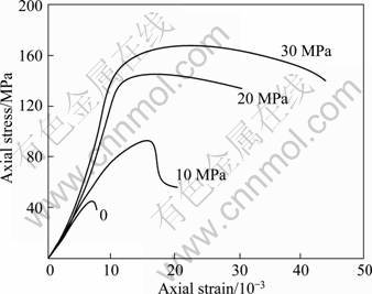
Fig. 1 Stress―strain curves of rock specimens under different confining pressures
Figure 2 shows the Mohr circle based on the test results in general triaxial compression. Cohesive force c and internal friction angle Φ of the rock specimen are 11.62 MPa and 34°, respectively, calculated by Mohr-Coulomb criterion.
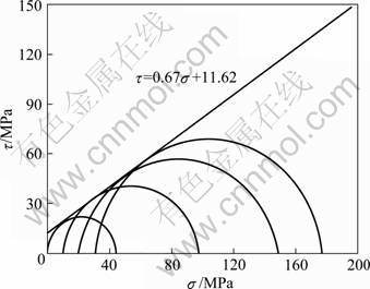
Fig. 2 Mohr strength curves in general triaxial compression
3.2 Test results at pre-peak unloading confining pressure
According to Scheme II, the stress―strain curves are shown in Fig. 3. There are processes of sudden decline of axial stress on rock failure under different confining pressure. It reflects relatively strong brittle damage characteristic and obvious shear failure plane on rock specimen.
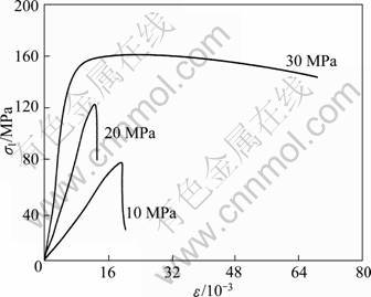
Fig. 3 Stress―strain curves of rock specimens at pre-peak unloading
3.3 Test results at post-peak unloading confining pressure
According to Scheme III, the stress―strain curves are shown in Fig. 4. It has no intensive failure as the pre-peak test Scheme II, the brittle characteristic of which is restrained, because existing plastic deformation has absorbed much elastic deformation energy [12]. The failure extent is larger than the pre-peak test results, and mostly rock specimens are X type shear failure.
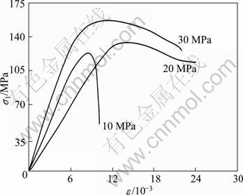
Fig. 4 Stress―strain curves of rock specimens at post-peak unloading
3.4 Typical loading and unloading test curve and analysis
Figure 5 shows the whole process of stress―strain curve under loading and unloading tests (confining pressure is 10 MPa). Axial compression failure increases the axial stress to reach the carrying capacity of rock specimen. However, unloading failure decreases the carrying capacity to reach axial stress of rock specimen causing yielding damage. Therefore, the deformation curves under two strain paths are greatly different.
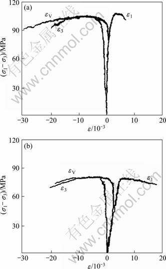
Fig. 5 Complete stress―strain curves of rock loading (a) and unloading (b) tests under 10 MPa
As shown in Fig. 5(a), there is an obvious characteristic of yielding feature during rock under axial compression test. The axial strain is about 7.6×10⁻³ before yielding, and the softening stage does not come until a big plastic deformation appears after yielding, then the macro failure happens at last. Figure 5(b) is the stress―strain curves under unloading confining pressure. The yielding confining pressure of rock specimen is about 6.5 MPa, which is declined by 3.5 MPa. The peak value of deformation curve in Fig. 5(b) is obviously less than that in Fig. 5(a), which illustrates that the confining pressure decrease in unloading failure is much smaller than the axial pressure increase in loading failure.
Axial strain ε1 increases gradually with the rise of confining pressure in the loading test. It is shown that confining pressure has obvious effect on the rock carrying capacity. Under the same confining pressure condition, however, the maximum axial strain decreases under unloading condition. It shows strong characteristics in the test. Lateral deformation ε3 around peak value in the general triaxial compression is smaller than that of unloading test under the same condition. Obvious lateral deformation increases with the rise of confining pressure under the unloading condition, especially at the critical failure point. When unloading to 60%-80% of the primary confining pressure in the test process, the strain reaches peak value and rock specimen destroys. Volumetric strain εV in general triaxial test keeps existing during the continuous compression process, but rock expansion phenomenon absolutely increases along with the rise of confining pressure under the unloading condition after unloading stage.
3.5 Rock parameter characteristics under unloading condition
Rock deformation parameters are generally obtained by uniaxial compression tests. The ratio of lateral strain ε3 and axial strain ε1 is Poisson ratio, μ, and the ratio of σ1 and ε3 is elastic modulus E:
 (1)
(1)
According to Eq. (1), μ'=-ε3/ε1 is used to get secant Poisson ratio. The ratio of lateral strain and axial strain at the same stress difference is still called Poisson ratio [13, 14]. Then the relation of Poisson ratio and confining pressure under different unloading conditions is shown in Fig. 6(a). Poisson ratio increases constantly along with the decreased confining pressure in the whole test process, and they are not in a linear relationship. When the unloading value in Fig. 6(a) reaches generally 60%-70% of the primary confining pressure, the rock specimen is manifested as severe failure and Poisson ratio has an obvious rise process.
Figure 6(b) shows the relationship between E and σ3, and the elastic modulus of rock experiences a very slow growth process with constant axial displacement while confining pressure σ3 decreases. It begins to reduce and has an obvious inflection point when reaching yielding intensity, and then decreases rapidly.
The intensity rule of Mohr-Coulomb based on primary stress form is expressed as [15]:
 (2)
(2)
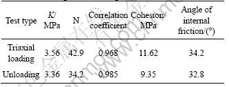
where K and N are the parameters of intensity rule and K can be used for evaluating the influence on rock intensity. The relation between K, N, c (cohesive force) and Φ (internal friction angle) is as follows:
 (3)
(3)
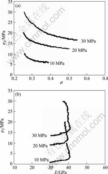
Fig. 6 Change characteristics of Poisson ratio (a) and elastic modulus (b) in process of unloading
Then
 (4)
(4)
Based on Eq. (4), Table 1 lists c and Φ values under loading and unloading conditions obtained at peak stress. From the table, it is known that c and Φ of unloading are smaller than those of loading, which shows that the rock intensity of unloading decreases faster than that of loading, and the decline rate is gradually reduced along with the rise of confining pressure.
Table 1 Correlation coefficient and angle of internal friction of rock under loading and unloading conditions
3.6 Rock failure characteristics under unloading condition
The results show that there are significant differences of mechanics properties between rock loading and unloading. As seen from Fig. 7, lateral deformation increases along with the rise of confining pressure, besides, the morphology of rock failure changes from single shear plane (the first two samples in Fig. 7) to complex fracture plane (the last two samples in Fig. 7).
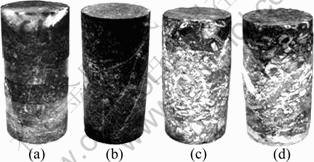
Fig. 7 Fracture photos of rock sample after general triaxial compression test: (a) 0 MPa; (b) 10 MPa; (c) 20 MPa; (c) 30 MPa
The failure modes under unloading condition are basically shear and brittle failure (Figs. 8 and 9). There is clear single failure plane and an upward trend of failure plane angle along with the rise of confining pressure. Rock specimen tends to have X type shear failure, cataclastic shapes and always powdery debris when stress intensity reaches a peak value.
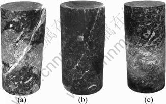
Fig. 8 Fracture photos of rock samples after pre-peak unloading test: (a) 10 MPa; (b) 20 MPa; (c) 30 MPa
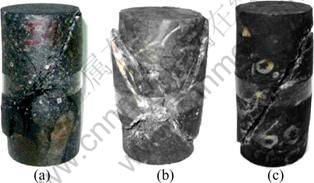
Fig. 9 Fracture photos of rock sample after post-peak unloading test: (a) 10 MPa; (b) 20 MPa; (c) 30 MPa
4 Conclusions
1) There are stronger brittle failure characteristics and obvious shear failure surface at pre-peak unloading. On the contrast, the brittle characteristics are restrained in the post-peak unloading test, and the softening stage does not appear immediately, but macro failure does not happen until it has a considerable plastic deformation. Rock failure under the loading condition mainly results in compressive deformation. However, it shows strong dilatation along the unloading direction under the unloading condition. So rock failure, even intense brittle failure, takes place under a smaller axial stress as long as unloading functions exist.
2) Rock Possion ratio gradually increases along with the decline of confining pressure in the unloading process with non-linear relation. Rock has an intense failure, and Possion ratio has an obvious increase process when unloading increases from 60% to 70% of the original confining pressure. At the beginning, rock elastic modulus increases slowly along with the decline of confining pressure, but decreases rapidly when unloaded to yielding strength. The weakening rate of rock intensity tends to be faster with easily failure under the unloading condition.
References
[1] LI Jian-lin. Unloading rock mass mechanics [M]. Beijing: China Water Power Press, 2003. (in Chinese)
[2] ZHOU X P, HA Q L, ZHANG Y X. Analysis of the deformation localization and the complete stress―strain relation for brittle rock subjected to dynamic compressive loads [J]. International Journal of Rock Mechanics and Mining Sciences, 2004, 41(2): 311-319.
[3] ZHOU Ke-ping, GAO Feng, HU Jian-hua, SU Jia-hong, ZHANG Shi-chao, DENG Hong-wei. Monitoring and analysis of fracture development in pre-splitting hole of cave inducement of roof [J]. Chinese Journal of Rock Mechanics and Engineering, 2007, 26(5): 1034-1040. (in Chinese)
[4] BROWN E T. Block caving geomechanics [M]. Australia: Julius Kruttschnitt Mineral Research Centre, 2003: 3-26.
[5] GAO Feng, ZHOU Ke-ping, DONG Wei-jun, SU Jia-hong. Similar material simulation of time series system for induced roof caving in continuous mining under backfill [J]. Journal of Central South University of Technology, 2008, 15(3): 356-360.
[6] SWANSON S R,BROWN W S. An observation of loading path independence of fracture rock [J]. International Journal of Rock Mechanics and Mining Sciences and Geomechanics Abstracts, 1971, 8(3): 277-281.
[7] WONG T, SZETO H, ZHANG J. Effect of loading path and porosity on the failure mode of porous rocks [J]. Applied Mechanics Reviews, 1992, 45(8): 281-293.
[8] CASTEN U, FAJKLEWICZ Z. Induced gravity anomalies and rock-burst risk in coal mines: A case history [J]. International Journal of Rock Mechanics and Mining Science, 1993, 41(1): l-13.
[9] HA Qiu-ling. Loading and unloading rock masses mechanics [J]. Chinese Journal of Geotechnical Engineering, 1998, 20(1): 114. (in Chinese)
[10] CHEN Wei-zhong, LIU Dong-du, YANG Jian-ping, TAN Xian-jun, WANG Chong-ge. Power function based mohr strength criterion for marble with unloading confining pressures [J]. Chinese Journal of Rock Mechanics and Engineering, 2008, 27(11): 2214-2220. (in Chinese)
[11] HUANG Run-qiu, HUANG Da. Experimental research on affection laws of unloading rates on mechanical properties of Jinping marble under high geostress [J]. Chinese Journal of Rock Mechanics and Engineering, 2010, 29(1): 21-33. (in Chinese)
[12] WANG bin, ZHU Jie-bing, WU Ai-qing, HU Jian-min, XIONG Zan-ming. Experimental study on mechanical properties of jinping marble under loading and unloading stress paths [J]. Chinese Journal of Rock Mechanics and Engineering, 2008, 27(10): 2138-2145. (in Chinese)
[13] HUANG Run-qiu, HUANG Da. Experimental research on mechanical properties of granites under unloading condition [J]. Chinese Journal of Rock Mechanics and Engineering, 2008, 27(11): 2205-2213. (in Chinese)
[14] VARASA F, ALONSO B E, ALEJANO L R. Study of bifurcation in the problem of unloading a circular excavation in a strain softening material [J]. Tunnelling and Underground Space Technology, 2005, 20(4): 311-322.
[15] SOFIANOS A I. Tunnelling mohr-coulomb strength parameters for rock masses satisfying the generalized Hoek-Brown criterion [J]. International Journal of Rock Mechanics and Mining Sciences, 2003, 40(3): 435-440.
诱导卸荷对岩石力学性质弱化的影响
高 峰, 周科平, 罗先伟, 翟建波
中南大学 资源与安全工程学院,长沙 410083
摘 要:研究在诱导卸荷作用下如钻孔、爆破、切缝和注水软化岩石的力学性能弱化规律。设计常规三轴加载、峰前和峰后卸载三种试验方案。试验结果表明:加载条件下的岩石破坏主要是由压缩变形所致,而卸荷条件下沿卸荷方向的岩石破坏为强烈的扩容所致。只要存在卸荷作用,岩石在较小的轴向应力下便可以发生破坏,甚至是强烈的脆性破坏。同时,卸荷过程中岩石泊松比随围压的降低逐渐增大。弹性模量随围压的减小先缓慢增加,在达到屈服强度后迅速降低。试验证明卸荷作用下岩石的强度弱化速率更快。
关键词:诱导崩落;卸荷;变形特征;破坏机制
(Edited by FANG Jing-hua)
Foundation item: Project (51074178) supported by the National Natural Science Foundation of China; Project (20110162120056) supported by the Special Research Fund for the Doctoral Program of Higher Education of China; Project (2011QNZT089) supported by the Young Teachers Boosting Special Subject of Central South University, China
Corresponding author: GAO Feng; Tel/Fax: +86-731-88879965; E-mail: gf81412@126.com
DOI: 10.1016/S1003-6326(11)61193-X

