J. Cent. South Univ. Technol. (2008) 15: 454-458
DOI: 10.1007/s11771-008-0085-9
Effects of cryogenic treatment on mechanical properties and microstructure of Fe-Cr-Mo-Ni-C-Co alloy
ZHU Yuan-zhi(朱远志)1, 2, YIN Zhi-min(尹志民)2, ZHOU Yong(周 勇)3,
LEI Quan-feng(雷全锋)3, FANG Wen-sheng(方文胜)3
(1. Key Laboratory for Ferrous Metallurgy and Resources Utilization of Ministry of Education,
Wuhan University of Science and Technology, Wuhan 430081, China;
2. School of Materials Science and Engineering, Central South University, Changsha 410083, China;
3. Danjiang Aluminum Ltd. Co., Danjiangkou 442700, China)
Abstract: Fe-Cr-Mo-Ni-C-Co alloy was quenched in liquid nitrogen and held for 24 h. Hardness tester, OM, XRD, SEM were used to investigate the mechanical properties and microstructures of the alloy. The results show that the hardness increases by 1-2 (HRC) and the compressive strength decreases slightly after cryogenic treatment. The increase in hardness is attributed to the transformation from austenite to martensite and the precipitation of the very tiny carbide η-Fe2C. The decrease in compressive strength is caused by residual stress. The great amount of carbides, such as Cr7C3 and Fe2MoC, in the alloy and the obvious difference in thermal expansion coefficient between these carbides and the matrix at the cryogenic temperatures lead to this residual stress. The microscopy of cryogenic martensite is different from that of the non-cryogenic martensite. The cryogenic martensite is long and fine; while the non-cryogenic martensite is short and coarse. There is obvious surface relief of the cryogenic martensite transformation. It is not orientational of this kind surface relief and the boundary of this surface relief is smooth and in a shape of butterfly. The surface relief in the non-cryogenic martensite is wide and arranged in parallel, and the boundary of surface relief is not smooth. These characteristics may imply different growth ways of the two kinds of martensite.
Key words: Fe-Cr-Mo-Ni-C-Co alloy; powder metallurgy; microstructure; mechanical properties; cryogenic martensite
1 Introduction
Valve and valve seat are key parts installed in the cylinder head of an engine to ensure the seal of the engine chamber. Valve and valve seat are composed of a tribopair. To lower the wear of this tribopair, a new type of PM Fe-Cr-Mo-Ni-C-Co alloy was designed for valve seat. The mechanical properties and microstructure of the alloy at room temperature were reported in other papers[1-7]. In installation, valve seat was assembled in interference fit with the cylinder head. Concretely, the valve seat was treated in liquid nitrogen and then quickly inserted into the cylinder head. Thus, the valve seat was fixed into the cylinder head firmly when its temperature returns to room temperature[1-2]. Microstructures and mechanical properties of the alloy will be affected by cryogenic treatment. Therefore, it is necessary to investigate whether a hardness of 39-45(HRC) and a compressive strength of 650 MPa required by the users can be ensured or not after cryogenic treatment. The influences of cryogenic treatment on microstructures and properties of quenched alloyed steel have been reported[3-7]. However, few studies focus on microstructure and mechanical properties of quenched and tempered PM Fe-based alloy. Here, microstructure and mechanical properties of PM Fe-Cr-Mo-Ni-C-Co alloy in cryogenic treatment were studied.
2 Experimental procedure
The as-received alloy samples were quenched at 1 000 ℃ and tempered at 650 ℃ for 2 h according to Ref.[8]. The alloy was dipped into liquid nitrogen directly and held for 24 h, then fetched out. Density, hardness and compressive strength were measured in a way as illustrated in Ref.[9].
OM, SEM and TEM were also conducted to investigate the microstructure evolution of the cryogenic treated alloy.
3 Results
3.1 Mechanical properties
Mechanica1 properties and density of the alloy are listed in Table 1. The results show that there is no change in density after cryogenic treatment. Hardness has an increase of 2.5(HRC) and there is a slight decrease in compressive strength. Both hardness and compressive strength can still satisfy the need of user.
3.2 Microstructure
Fig.1 shows the optical micrographs of the alloy. It can be seen that the matrix of the as-received alloy is the tempered sorbite, and the retained austenite (gray phase within a grain) and the coarsened carbides distribute on grain boundary. Usually, the matrix of quenched and tempered ferrite alloy should be sorbite. But in this alloy, the retained austenite in the matrix may be attributed to a great deal of tiny carbides and solid solution of chromium and carbon. After cryogenic treatment, part of the retained austenite was transferred into martensite. The original retained austenite was separated into small pieces by the needle-like martensite.
To make an investigation of the microstructural evolution, SEM analysis was performed, and the results are shown in Fig.2. The microstructure of cryogenic martensite is different from that of the non-cryogenic martensite. In the cryogenic treated alloy, the cryogenic martensite is long and thin. There is surface relief of the cryogenic martensite transformation. There is no obvious orientation in this kind of surface relief and the boundary of this surface relief is smooth and in a shape of butterfly. However, the non-cryogenic martensite is coarse and short (Fig.2(a)). The surface relief in the non-cryogenic martensite is wide and arranged in parallel. The boundary of surface relief is not smooth. These characteristics may imply different growth ways of the two kinds of martensite.
XRD analysis was also performed to investigate the phase transformation in cryogenic treatment. The diffraction patterns are shown in Fig.3.
From XRD pattern, compared with the as-received alloy, two aspects of changes of the alloy by cryogenic treatment are obvious. Firstly, the intensity of the diffraction peak of retained austenite in the alloy after cryogenic treatment becomes lower, which means that the retained austenite has been transferred into martensite in cryogenic treatment. Secondly, there is a diffraction peak on the left of the main diffraction peak of retained austenite. It is the diffraction peak of plane (020) of η-Fe2C. It can be concluded that η-Fe2C precipitates in the cryogenic treatment. Because the size of this carbide is too small to be found in the SEM image.
TEM micrographs are shown in Fig.4. It can be seen that there are carbides with a size of about 10 nm precipitated on martensite plane. It is confirmed to be η-Fe2C by the selected area diffraction.
4 Discussion
4.1 Hardness and strength of cryogenic treated alloy
Hardness of the alloy is increased after cryogenic treatment, which is mainly attributed to the transformation of the retained austenite into martensite. Because martensite is a supersaturated solid solution. The formation of martensite leads to lattice distortion. The stress and strain field forms in the interface between martensite and its adjacent austenite. The resistance of
dislocation movement increases. Hence, the hardness and the strength of the alloy increase. On the other hand, the martensite separates the retained austenite into pieces, which means that the retained austenite is refined. According to Hell-Petch equation:
σs=σ0+Kyd-1/2 (1)
where σs is the yield strength; σ0 is the original strength; d is the diameter of the grain and Ky is the constant. The size of the austenite is less than 1/5 of the original one.However, the amount of austenite is just a small fraction in the total and Ky is also small. Therefore, the increment of strength and hardness is also minor.
Table 1 Comparison of mechanical properties of studied alloys after different heat treatments

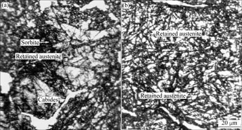
Fig.1 SEM images of studied alloys: (a) As-received alloy; (b) Cryogenic treated alloy
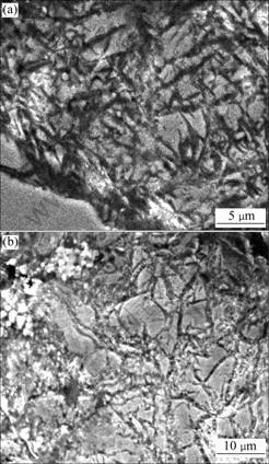
Fig.2 SEM images of alloy: (a) As received alloy; (b) Cryogenic treated alloy
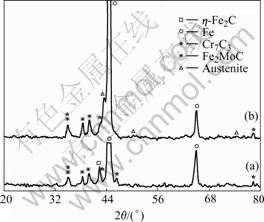
Fig.3 XRD patterns of alloys: (a) Cryogenic treatment; (b) As- received
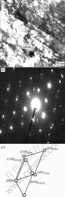
Fig.4 TEM image (a), selected area diffraction pattern (b) and index calibration of diffraction pattern (c) of cryogenic treated alloy
Another change of the alloy in cryogenic treatment is the precipitation of η-Fe2C from martensite. These carbides are very fine and lead to an additional increase in strength of the martensite. But because the fraction of the martensite is small, the increase in strength is minor.
The fractograph is shown in Fig.5. It can be seen that there are some fine and long (needle-like) phases in the cryogenic treated alloy and these phases are not broken in the fracture of the alloy, which means that the micro-strength of the phases is high. But in the as-received alloy, the needle-like phases are not detected (Fig.5(b)). It is sure that these phases are martensite. Additionally, secondary cracks can also be seen in the fractograph of the cryogenic treated alloy. The cracks originate from carbides distributed on grain boundaries. Some cracks separate the carbides into two parts. It is obvious that the micro-parts in the alloy shrink in the cooling process. But the expansion coefficient of carbides is much lower than those of ferrite and austenite. There is tensile stress on the carbides. During the rising of temperature after cryogenic treatment, there is compressive stress on the carbides. The stress on carbides during the cryogenic treatment is schematically illustrated in Fig.6.
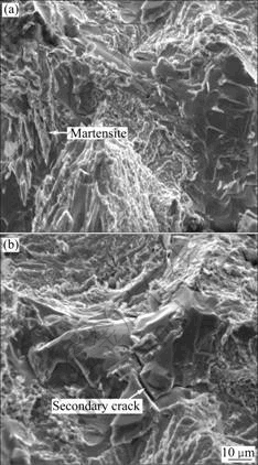
Fig.5 Fractographs of alloys: (a) As-received; (b) Treated at cryogenic temperature
It can be seen that the compressive stress on the carbides during the rising of temperature after cryogenic treatment would balance the tensile stress in the cooling process. Therefore, there are no obvious changes in the mechanical properties of the alloy.
4.2 Microstructures
4.2.1 Formation of martensite
When the austenite is quenched to room temperature, it transfers into supersaturated solid solution―martensite. The formation of martensite leads to residual compressive stress on the adjacent austenite, which makes the transformation of austenite into martensite more difficult. Even if the temperature of the alloy is cooled to room temperature, some austenite still cannot be transferred into martensite. Moreover, multi-alloy elements in the alloy stabilize the austenite at elevated temperature[10-14]. Even if the alloy has been tempered at 600 ℃, the austenite cannot be decomposed completely (see Fig.7). The retained austenite is transferred into martensite at a much higher driving force during the cryogenic treatment.

Fig.6 Stress on carbides in alloy during heat treatment process at cryogenic temperature: (a) Cooling to cryogenic temperature; (b) Heating to room temperature
Fig.7 Retained austenite in alloy quenched at 1 000 ℃ and tempered at 600℃
There is great difference in the micrograph of cryogenic martensite and non-cryogenic martensite.
There is obvious surface relief in the cryogenic martensite transformation. It is not orientational of this kind of surface relief and the boundary of this surface relief is smooth and in the shape of butterfly. The surface relief in the non-cryogenic martensite is wide and arranged in parallel. The boundary of surface relief is not smooth. The probable reason is that the matrix is relatively soft when martensite forms in the quenching process at relatively high temperatures. It is easy for martensite to nucleate and grow. However, for cryogenic treatment, the temperature is much lower. And additionally, the carbon content in the alloy is very high and a lot of fine dispersed carbides are distributed in matrix, which enhances the resistance of martensite transformation and martensite growth. These characteristics may imply different growth ways of the two kinds of martensite. The martensite can just grow along so-called “soft” location.
4.2.2 Dynamics of carbide precipitation
At a very low temperature during cryogenic treatment, the diffusion of atoms is very slow. In the cooling process, the great bulk shrinkage of the alloy makes the FCC austenite transfer into BCC martensite. This phase transformation leads to the increase in density of dislocations and vacancies. The supersaturated dislocations and vacancies enhance the diffusion coefficient of carbon. Carbon atoms are driven to segregate dislocations by the interaction of stress field around dislocations with interstitial carbon atoms. This microstructural evolution induces the precipitation of very tiny carbides during the cryogenic treatment. At a liquid nitrogen temperature, the diffusion of carbon is extraordinarily slow. However, in the heating process after the cooling process, carbides precipitate. The precipitation temperature of carbides is over 100 K[15].。
5 Conclusions
1) The hardness of the Fe-based alloy increases 1-2 (HRC) and compressive strength decreases slightly after cryogenic treatment.
2) The increase in hardness is attributed to the transformation from austenite to martensite and the precipitation of the very tiny carbide η-Fe2C. The decrease in compressive strength is caused by residual stress. The great amount of carbides such as Cr7C3 and Fe2MoC in the alloy and the big difference between these carbides and the matrix in thermal expansion coefficient at the cryogenic temperatures lead to this residual stress.
3) There is surface relief in the cryogenic martensite transformation. There is no obvious orientation in this kind surface relief and the boundary of this surface relief is smooth and in the shape of butterfly. The surface relief in the non-cryogenic martensite is wide and arranged in parallel and the boundary of surface relief is not smooth. These characteristics may imply different growth ways of the two kinds of martensite.
References
[1] LIANG Yi-tian, YANG Qing-rui. Study on high nickel cast iron engine stigma seat [J]. Foundry Technology, 1997, 5(2): 53-55.
[2] ZHU Pai-long, YANG Jian. A method of taking out valve insert [J]. Machinery Design & Manufacture, 2004, 3(5): 12-13.
[3] KIYOHIKO N, SHINJI S, KAGAO O, HIROSHI S. Fine-blanking performance of non-magnetic high manganese cryogenic steel and its application to superconducting dipole magnet [J]. Cryogenics, 1994, 34(Suppl): 477-480.
[4] FREDJ B, HABIB S. Effects of the cryogenic cooling on the fatigue strength of the AISI 304 stainless steel ground components [J]. Cryogenics, 2006, 46(6): 439-448.
[5] HAN J K, KIM Y G.  Low cycle fatigue behaviour of a cryogenic Fe-30Mn-5Al-0.1NB-0.3C steel [J]. Materials Science and Engineering A, 1987, 91(2): 73-79.
[6] COLLINS D N, DORMER J. Deep cryogenic treatment of a 2D cold-work tool steel [J]. Heat Treatment of Metals, 1997, 24(3): 71-74.
[7] FU Rui-dong, ZHENG Yang-zeng, REN Yi-bin. Mechanical properties of 32Mn-7Cr-0.6Mo-0.3N austenitic steel for cryogenic applications [J]. Journal of Materials Engineering and Performance, 2001, 10(4): 456-459.
[8] ZHU Yuan-zhi, YIN Zhi-min, ZENG Yu. Effects of heat treatment on microstructure and mechanical properties of Fe-Co-Ni-Cr-Mo-C alloy [J]. Journal of Central South University of Technology, 2004, 11(3): 229-234.
[9] ZHU Yuan-zhi, YIN Zhi-min. The hot densification of a Fe-based sintered alloy Fe-Cr-Mo-Ni-Co-C [J]. Journal of Central South University: Science and Technology, 2006, 37(3): 456-460. (in Chinese)
[10] ERIL N, HOLMEDAL B, EVANGELISTA E. Modelling grain boundary strengthening in ultra-fine grained aluminum alloys [J]. Materials Science and Engineering A, 2005, 410/411(25): 178-182.
[11] XU Liu-jie, XING Jian-dong, WEI Shi-zhong. Artificial neural network prediction of retained austenite content and impact toughness of high-vanadium high-speed steel (HVHSS) [J]. Materials Science and Engineering A, 2006, 433(1/2): 251-256.
[12] LI Xi-bing. Influence of solid-solution treatment on mechanical properties of nickel-chromium-molybdenum alloy and analysis of its fracture [J]. Journal of Central South University of Technology: Natural Science, 2004, 35(4): 353-357. (in Chinese)
[13] GUO Jiang-ting, WANG Shu-he, XIONG Liang-yue, WU Dao-hong, DENG Wen, HUANG Yu-yang. Influence of chemical composition and alloying elements on microdefects and electron density in Ni-Al alloys [J]. Transactions of Nonferrous Metals Society of China, 2002, 12(3): 370-374.
[14] LU Bin, LIANG Ying. The effect of quenching process on the structure and properties of the bimetal SAW [J]. Journal of Central South University of Technology: Natural Science, 1999, 30(1): 67-70. (in Chinese)
[15] PENG Kuang-ding. The diffusion of carbon in steel in cryogenic treatment [J]. Journal of Yunnan University: Natural Edition, 1996, 18(3): 231-234. (in Chinese)
Received date: 2008-01-09; Accepted date: 2008-04-09
Corresponding author: , PhD, Associate Professor; E-mail: tozyzl@163.com
(Edited by YANG Hua)

