


Trans. Nonferrous Met. Soc. China 22(2012) 1526-1532
A general method to calculate passive earth pressure on rigid retaining wall for all displacement modes
PENG Shu-quan, LI Xi-bing, FAN Ling, LIU Ai-hua
School of Resources and Safety Engineering, Central South University, Changsha 410083, China
Received 10 May 2011; accepted 4 November 2011
Abstract: A general analytical method to calculate the passive rigid retaining wall pressure was deduced considering all displacement modes. First, the general displacement mode function was setup, then the hypotheses were made that the lateral passive pressure is linear to the corresponding horizontal displacement and the soil behind retaining wall is composed of a set of springs and ideal rigid plasticity body, the general analytical method was proposed to calculate the passive rigid retaining wall pressure based on Coulomb theory. The analytical results show that the resultant forces of the passive earth pressure are equal to those of Coulomb’s theory, but the distribution of the passive pressure and the position of the resultant force depend on the passive displacement mode parameter, and the former is a parabolic function of the soil depth. The analytical results are also in good agreement with the experimental ones.
Key words: rigid retaining wall; displacement mode; passive earth pressure; parabolic function
1 Introduction
Rigid retaining wall is largely used in geotechnical engineering including piles, the gravity retaining wall, and bridge pier. The passive earth pressure is affected by many factors, such as the relative density of the backfill [1], the over-consolidation ratio of the backfill [2], the soil arching in the backfill [3], the ratio of width and height of the retaining wall [4] and the groundwater flow [5]. Comparing with the above factors, the passive displacement modes of rigid retaining wall have more distinct effect on the passive earth pressure [6-8]. So the passive earth pressure on rigid retaining wall for different passive displacement mode must be studied carefully. The passive displacement modes include the following five different modes: 1) rigid retaining wall translating mode (T), 2) over the top of rigid retaining wall rotating mode (RTT), 3) on the top rotating mode (RT, the exceptional case of RTT), 4) over the bottom rotating mode (RBT) and 5) on the bottom rotating mode (RB, the exceptional case of RBT) as shown in Fig. 1.
Generally, the passive earth pressure distribution is linear in the T mode. However, the distribution of passive earth pressure and the applying position of resultant force are more complicated for either RTT mode or RBT mode. Several researchers recently had given their solutions. The pioneering work done by FANG et al [6,7] through model experiment showed that the distribution of passive earth pressure on rigid retaining wall varied with the displacement mode, which is still being used worldwide. XU et al [8] completed the comparative studies of the model experiment and numerical analysis. A few literatures dealt with the analysis of rigid retaining wall under T mode. For example, the passive earth pressure by Coulomb theory can fit the T mode. The displacement-related calculation formulas of passive earth pressure in T mode were deduced [9-14]. And RT mode-related passive earth pressure was studied by KONG and ZHANG [15]. It is noted that the passive earth pressure, corresponding to the five different displacement modes, namely T, RTT, RT, RBT and RT modes, was computed by using different methods, e.g. the finite element method [16-18], the discrete element [19,20] and the triangular slice method [21]. But none of the above solutions can fit all displacement modes. This study is focused on building a general analytical method to calculate the passive earth pressure on rigid retaining wall which can fit all displacement modes.
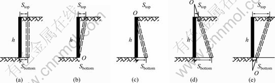
Fig. 1 Passive displacement modes of rigid retaining wall: (a) T mode; (b) RB mode; (c) RT mode; (d) RTT mode; (e) RBT mode
2 General method to calculate passive earth pressure
2.1 Passive displacement of rigid retaining wall
The initial wall (the black wall in Fig. 1) moves toward the terminative wall (the dashed wall in Fig. 1) with the top displacement Stop and the bottom displacement Sbottom (Fig. 2). If a passive displacement mode parameter m is introduced into and defined as the ratio of x/h (Fig. 2), the ratio of Stop/Sbottom can be expressed by Eq. (1). And the relationship between m and displacement mode can be illuminated in Table 1.
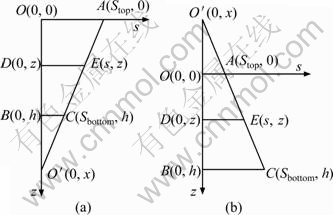
Fig. 2 Analysis of passive displacement modes of rigid retaining walls: (a) m≥1, Smax=Stop; (b) m≤0, Smax=Sbottom
Table 1 Relationship between m and displacement mode

 (1)
(1)
where m=x/h.
The point O may locate over the top of the retaining wall or below the bottom of the retaining wall, which depends on the passive displacement mode. When the point O is below the bottom, m≥1, and the maximum displacement of retaining wall, Smax=Stop; when the point O is over the top, m ≤0, and Smax=Sbottom.
The displacement of the initial wall at the point corresponding depth z is defined as s, which is given by:
 (2)
(2)
2.2 General calculation of passive earth pressure
As shown in Fig. 3, the backfill behind rigid retaining wall is assumed as a composed body with one ideal rigid plasticity body and a series of springs, and then the magnitude of passive earth pressure p along the height of retaining wall is a linear function of displacement s.
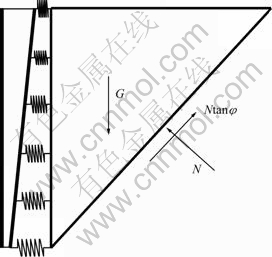
Fig. 3 Schematic diagram to calculate passive earth pressure (G is the gravity of soil body, N is the pressure on the failure surface, φ is the internal friction angle of backfill)
 (3)
(3)
where k is the rigid coefficient of the unit backfill.
When s=0, then b=K0ρgz, where K0 is the coefficient of static lateral pressure on retaining wall, ρ is the density of backfill and g is the gravity acceleration.
When S=Smax, then p= , where
  is the local passive earth pressure coefficient of the local backfill in passive limited state, which is on the top point or the bottom point of rigid retaining wall.
 (4)
(4)
Thus, Eq. (3) can be rewritten as:
 (5)
(5)
The passive resultant force on retaining wall is calculated by using the Mohr-Coulomb rule and the static-equilibrium method, and should be equal to the one based on the Coulomb theory, e.g.
 (6)
(6)
where Kp is the passive earth pressure coefficient of Coulomb theory, and

where φ is the internal friction angle of backfill, and δ is the friction angle between backfill and rigid retaining wall.
Based on Eqs. (4)-(6), the local passive earth pressure coefficient Kp' is then given as:
 (7)
(7)
Based on Eq. (4) and Eq. (7), the rigid coefficient of the backfill k can be expressed as:
 (8)
(8)
Obviously, k varies directly with Kp, K0 and the density of backfill, and inversely with the maximum displacement of backfill behind rigid retaining wall Smax, but is nonlinear with the displacement mode parameter m.
Based on Eqs. (2), (5) and (8), the distribution of the passive earth pressure p can be expressed in a general form:
 (9)
(9)
The point of the passive earth pressure resultant force z0 is given by:
 (10)
(10)
After simplification, Eq.(10) can be rewritten as:
 (11)
(11)
It is noted that the passive earth pressure p and the point of the resultant force of the passive earth pressure z0 vary with the displacement mode parameter m.
From Eq. (9) the value of passive earth pressure on the height of (2/3)h is always equal to (2/3)Kpgh, so the area ratio of p and Kpρgz with the depth z belonging to [0, (2/3)h] can explain the characteristic change of p with displacement mode parameter m. In order to estimate the extent of effect of the displacement mode parameter m on the passive earth pressure p, a new parameter R is introduced into and defined as:
 (12)
(12)
The above equation can be simplified as:
 (13)
(13)
3 Results and discussion
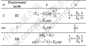
A general form to calculate the distribution of passive earth pressure p for all passive displacement modes is considered by Eq. (9). It is a parabolic function of the soil depth z, and has a non-linear relationship to the passive displacement mode coefficient m. The position of the resultant force of the passive earth pressure z0 can be calculated by Eq. (10) or (11), and is usually affected by m, K0 and Kp. The calculation formulas of p and z0 for the RT, T and RB modes can be summarized in Table 2.
The value of z0 will drop in the following interval:
 (14)
(14)
The method of Coulomb or Rankine theory, the horizontal different element method, the displacement- related passive earth pressure calculation formulas [9-11], etc, can only fit the T mode. The proposed general analytical method to calculate the passive earth pressure on rigid retaining wall can fit all displacement modes, and is more simple and practical than the finite element method [16,17], the discrete element method [19], and the semi-empirical approach [20]. So the proposed general analytical method in this work has more advantages over the other methods.
Table 2 Calculation formulas of p and z0 in RT, T and RB modes
3.1 Effect of passive displacement mode m
Figure 4 shows the distribution of the passive earth pressure on rigid retaining wall for φ=33°, δ/φ=1/2, ρg=18 kN/m3, with different displacement modes. When m is large than 1 (RBT mode), the distribution of passive earth pressure along the retaining wall is convex, and when m is less than 0 (RTT mode), the passive earth pressure distribution is concave. While m is less than -5 or large than 5, the distribution of passive earth pressure is almost linear. And this meets with the experimental result by FANG et al [1], and also meets with the numerical analytical result by the finite element method [16,17], and the discrete element [19].

Fig. 4 Passive earth pressure distribution with different displacement mode parameter
Figure 5 shows R and the position of the resultant force of the passive earth pressure on rigid retaining wall z0 for φ=33°, δ/φ=1/2 and ρg=18 kN/m3, with different displacement modes. The resultant force point of passive earth pressure for Coulomb theory is at (1/3)h, but the R and z0 vary with different displacement mode parameter m. When m increases from -10 to 0 (RTT mode), R moves from 0.5 to 0.05 and z0 from 0.26 to 0.33, and when m from 1 to 10 (RBT mode), R from 0.05 to 0.95 and z0 from 0.33 to 0.50, so the variable intervals of R and z0 for the RBT mode are more large than the ones for the RBT mode, so it is concluded that the RBT mode affects more greatly p and z0 than the RTT mode.
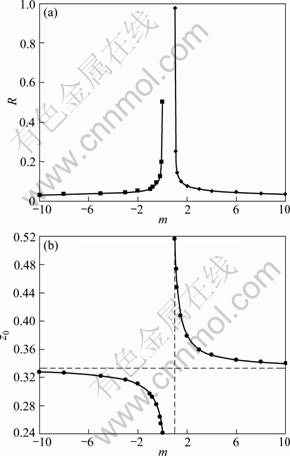
Fig. 5 Effect of m on R (a) and z0 (b)
Especially, when m belongs to [-2, 0] or [1, 2], z0 and R are significantly affected by the retaining wall displacement mode parameter m, and are very sensitive to m; and when m is great than 2.0 or less than -2.0, z0 and R are less sensitive to the displacement mode parameter m. This finding is in good agreement with experimental results by FANG et al [7].
3.2 Effect of internal friction angle on R and z0
Figure 6 shows R and z0 for δ/φ=1/2, ρg=18 kN/m3, and m=-5, -2, -1, 0, 2, 5, with different internal friction angle φ. When the internal friction angle φ increases from 20° to 46°, R increases from 0.82 to 1.1 and z0 from 0.52 to 0.58 under m=-1 (RB mode); while under the RBT and RTT displacement mode, R and z0 are almost constant with different internal friction angles.
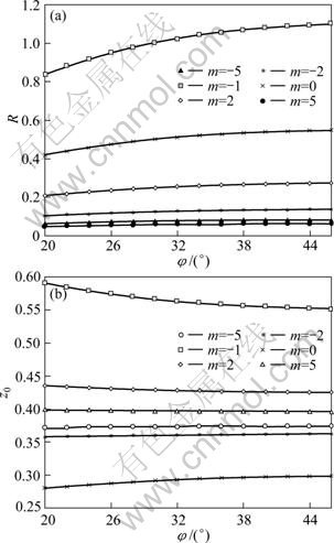
Fig. 6 Effect of internal friction angle on R (a) and z0 (b)
3.3 Effect of friction angle between backfill and rigid retaining wall on R and z0
Figure 7 shows R and z0 for φ=30°, ρg=18 kN/m3, m=-5, -2, 0, 1, 2, 5, with different friction angle between backfill and rigid retaining wall δ. R and z0 are almost constant with δ under any one of displacement modes, and are also not sensitive to δ
4 Comparison of results
The validation of the present methodology for the calculation of the passive earth pressure on rigid retaining wall can be verified by a comparative study with existing work. Figure 8 presents a comparison among the distribution of passive earth pressure obtained by the general analytical method in this work, the result of the Coulomb theory and the experimental result of FANG et al [1] with the height of rigid retaining wall 0.5 m, the density of sand 1550 kg/m3, the internal friction angle 30.9° and the friction angle between backfill and rigid retaining wall 10°.
Under the RB displacement mode (m=1.001), the distribution of passive earth pressure on the retaining wall p by the present method in this work meets well with the results of FANG et al [1], while the result of Coulomb theory obviously does not meet well (Fig. 8(a)). Under the T mode (m=10), p is much close to each other among the above three methods (Fig. 8(b)). Under RT mode (m=-10-7), p by the general analytical method meets better with experimental result than that by Coulomb theory.
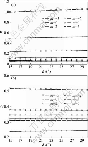
Fig. 7 Effect of friction angle between backfill and rigid retaining wall on R (a) and z0 (b)
Table 3 presents the z0 obtained by the general analytical method in this work and the model experiment result of FANG et al [1]. The results show that z0 is nearly closed under the T mode and RB mode, but the error of z0 under RT mode is much large.
Table 3 Comparison of z0 obtained by different calculating methods
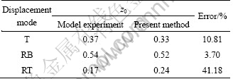
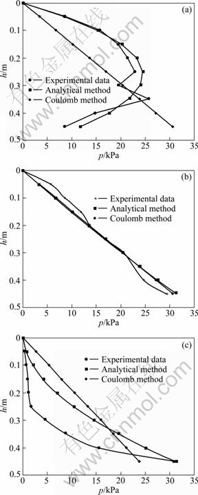
Fig. 8 Comparison of passive earth pressure wtih different methods: (a) RB mode; (b) T mode; (c) RT mode
5 Conclusions
1) For the general analytical method, the two hypotheses about the soil behind retaining wall and the lateral passive earth pressure along the retaining wall are reasonable.
2) The resultant force of passive earth pressure is equal to the one by Coulomb theory, but the distribution of passive earth pressure and the resultant force point of passive earth pressure depend more distinctly on the passive displacement mode parameter than the internal friction angle and the friction angle between backfill and rigid retaining wall.
3) The results obtained by the general analytical method are in good agreement with the experimental results under T and RB mode, but do not meet much well under RT mode because the effect of soil arching is ignored.
References
[1] FANG Y S, HO Y C, CHEN T J. Passive earth pressure with critical state concept [J]. Journal of Geotechnical and Geoenvironmental Engineering, 2002, 128: 651-659.
[2] HANNA A, AI KHOURY I. Passive earth pressure of overconsolidated cohesionless backfill [J]. Journal of Geotechnical and Geoenvironmental Engineering, 2005, 131(8): 978-986.
[3] PENG Shu-quan, ZHOU Jian, FAN Ling, LIU Ai-hua. Research on earth pressure of rigid retaining wall considering soil arching [J]. Rock and Soil Mechanics, 2008, 29(10): 2701-2707. (in Chinese)
[4] BENMEBAREK S, KHELIFA T, BENMEBAREK N, KASTNER R. Numerical evaluation of 3D passive earth pressure coefficients for retaining wall subjected to translation [J]. Computers and Geotechnics, 2008, 35(1): 47-60.
[5] BENMEBAREK N, BENMEBAREK S, KASTNER R, SOUBRA A H. Passive and active earth pressures in the presence of groundwater flow [J]. Geotechnique, 2006, 56(3): 149-158.
[6] FANG Y S, ISHIBASHI I. Static earth pressure with various wall movement [J]. Journal of Geotechnical Engineering, 1986, 112(3): 317-333.
[7] FANG Y S, CHEN T J, WU B F. Passive earth pressures with various wall movements [J]. Journal of Geotechnical Engineering, 1994, 120(8): 1307-1323.
[8] XU Ri-qing, CHEN Ye-kai, YANG Zhong-xuan, GONG Xiao-nan. Experimental research on the passive acting on a rigid wall [J]. Chinese Journal of Geotechnical Engineering, 2002, 24(5): 569-575. (in Chinese)
[9] MEI Guo-xiong, CHEN Qi-ming, SONG Lin-hui. Model for predicting displacement dependent lateral earth pressure [J]. Canadian Geotechnical Journal, 2009, 46(8): 969-975.
[10] LU Guo-sheng. Calculation method of earth pressure considering displacement [J]. Rock and Soil Mechanics, 2004, 25(4): 586-589. (in Chinese)
[11] ZHANG Xiao-ping, HU Ming-liang. Calculation method for earth pressure considering displacement [J]. Transactions of Nanjing University of Aeronautics and Astronautics, 2009, 26(3): 229-234. (in Chinese)
[12] GHAHRAMANI A, SABZEVARI A. A load displacement analysis for passive earth pressure problems [J]. Acta Technica, 1974, 78(1-2): 177-197.
[13] JAHANANDISH M, BEPOOR L, GHAHRAMANI A. Load displacement characteristics of retaining walls [C]//Publications Committee of XII ICSSMFE Staff. Proceedings of the Twelfth International Conference on Soil Mechanics and Foundation Engineering. Rotterdam, Dutch: A. A. BALKEMA, 1989: 243-246.
[14] ABHIJIT R, RANJAN P N. Effect of arching on passive earth pressure for rigid retaining walls considering translation mode [C]// GRIFFIS L. Proceedings of 2009 Structures Congress-Don't Mess with Structural Engineers: Expanding Our Role. America: Structural Engineering Institute of ASCE, 2009: 2784-2793.
[15] KONG Liang, ZHANG Ji-quan. Distribution of passive earth pressure with rigid retaining wall rotating about wall top [J]. Chinese Journal of Rock Mechanics and Engineering, 2004, 23(1): 4460-4462. (in Chinese)
[16] BORJA R I, LAI T Y. Propagation of localization instability under active and passive loading [J]. Journal of Geotechnical and Geoenvironmental Engineering, 2002, 128(1): 64-75.
[17] NAKAI T. Finite element computations for active and passive earth pressure problems of retaining wall [J]. Soil and Foundations, 1985, 25(3): 982-1012.
[18] SHIAU J S, AUGARDE C E, LYAMIN A V, SLOAN S W. Finite element limit analysis of passive earth resistance in cohesionless soils [J]. Soils and Foundations, 2008, 48(6): 843-850.
[19] CHANG C S, CHAO S J. Discrete element analysis for active and passive earth pressure distribution on retaining wall [J]. Computers and Geotechnics, 1994, 16(4): 291-310.
[20] RAO K S, SUBBA N S, CHOUDHURY D. Determination of displacement-related passive earth pressure [J]. Geotechnical Engineering, 2004, 35(2): 79-85.
[21] ZHU Da-yong, QIAN Qi-hu. Determination of passive earth pressure coefficients by the method of triangular slices [J]. Canadian Geotechnical Journal, 2000, 37(2): 485-491.
不同位移模式刚性挡墙被动土压力通用计算方法
彭述权, 李夕兵, 樊 玲, 刘爱华
中南大学 资源与安全工程学院, 长沙 410083
摘 要: 刚性挡墙被动位移模式包括平移(T)、绕墙顶一点转动(RTT)、绕墙顶转动(RT)、绕墙底一点转动(RBT)和绕墙底转动(RB)。挡墙位移模式对刚性挡墙被动土压力分布有重要影响。这一点目前缺乏理论解析解, 需要建立考虑位移模式影响的刚性挡墙被动土压力分析方法。为此, 建立被动位移模式函数, 提出土体由一系列弹簧和理想弹塑性体组成, 沿挡墙任一点被动土压力与相应水平位移成线性关系假定, 得到了不同位移模式刚性挡墙被动土压力的计算公式。研究结果表明,被动土压力合力与Coulomb被动土压力的计算结果相等, 但是被动土压力分布与挡墙位移模式参数m密切相关, 为土体深度z的二次函数。被动土压力合力作用点也与挡墙位移模式参数m密切相关。所得的被动土压力分布与试验结果吻合较好。所提的不同位移模式刚性挡墙被动土压力通用计算方法具有重要的理论分析价值。
关键词: 刚性挡墙;位移模式;被动土压力;二次函数
(Edited by YUAN Sai-qian)
Foundation item: Project (201012200094) supported by the Freedom Exploration Program of Central South University of China; Project (20090461022) supported by the China Postdoctoral Science Foundation; Project (2010ZJ05) supported by the Science and Technology supporting Program of Xinjiang Production and Construction Corps in China
Corresponding author: PENG Shu-quan; Tel:+86-731-88879612; E-mail: pqr97linger@163.com
DOI: 10.1016/S1003-6326(11)61351-4

