Behavior of double K-BRB braces under lateral loading
来源期刊:中南大学学报(英文版)2021年第8期
论文作者:Ali GHAMARI Hadi HAERI Amir JOHARI NAEIMI Zohreh NAJMI Vahab SARFARAZI
文章页码:2394 - 2406
Key words:buckling resisting brace (BRB); stiffness; ultimate strength; ductility; brace; energy absorption
Abstract: The buckling resisting brace (BRB) is an efficient system against lateral loads that enjoy high seismic energy absorption capacity. Although desirable behavior of BRBs has been confirmed, the stiffness of the system is not desirable that it can be compensated by changing the configuration of BRB braces. In so doing, the configuration in the form of double K (DK) is investigated to achieve more favorable behavior. Also, the required mathematical formulas were proposed to design the system. Comparison of DK system with other conventional BRB showed that the DK system has a better structural performance and is more economical (due to needing less core area) than other conventional BRB. Numerical results indicated that the DK system increases the lateral ultimate strength, lateral nonlinear stiffness, and energy absorption. Besides, the DK configuration reduces the axial forces created in columns in the nonlinear zone. Reducing material demand, created forces in the main frame, and also increasing of nonlinear stiffens by DK improve the structure’s safety.
Cite this article as: Ali GHAMARI, Hadi HAERI, Amir JOHARI NAEIMI, Zohreh NAJMI, Vahab SARFARAZI. Behavior of double K-BRB braces under lateral loading [J]. Journal of Central South University, 2021, 28(8): 2394-2406. DOI: https://doi.org/10.1007/s11771-021-4668-z.

J. Cent. South Univ. (2021) 28: 2394-2406
DOI: https://doi.org/10.1007/s11771-021-4668-z

Ali GHAMARI1, Hadi HAERI2, Amir JOHARI NAEIMI3, Zohreh NAJMI4, Vahab SARFARAZI5
1. Department of Civil Engineering, Darreh Shahr Branch, Islamic Azad University, Darreh Shahr, Iran;
2. State Key Laboratory for Deep GeoMechanics and Underground Engineering, Beijing 100083, China;
3. Department of Civil Engineering, Amirkabir University of Technology, Tehran, Iran;
4. Department of Structural Engineering, Aria University of Science and Sustainability, Tehran, Iran;
5. Department of Mining Engineering, Hamedan University of Technology, Hamedan, Iran
 Central South University Press and Springer-Verlag GmbH Germany, part of Springer Nature 2021
Abstract: The buckling resisting brace (BRB) is an efficient system against lateral loads that enjoy high seismic energy absorption capacity. Although desirable behavior of BRBs has been confirmed, the stiffness of the system is not desirable that it can be compensated by changing the configuration of BRB braces. In so doing, the configuration in the form of double K (DK) is investigated to achieve more favorable behavior. Also, the required mathematical formulas were proposed to design the system. Comparison of DK system with other conventional BRB showed that the DK system has a better structural performance and is more economical (due to needing less core area) than other conventional BRB. Numerical results indicated that the DK system increases the lateral ultimate strength, lateral nonlinear stiffness, and energy absorption. Besides, the DK configuration reduces the axial forces created in columns in the nonlinear zone. Reducing material demand, created forces in the main frame, and also increasing of nonlinear stiffens by DK improve the structure’s safety.
Key words: buckling resisting brace (BRB); stiffness; ultimate strength; ductility; brace; energy absorption
Cite this article as: Ali GHAMARI, Hadi HAERI, Amir JOHARI NAEIMI, Zohreh NAJMI, Vahab SARFARAZI. Behavior of double K-BRB braces under lateral loading [J]. Journal of Central South University, 2021, 28(8): 2394-2406. DOI: https://doi.org/10.1007/s11771-021-4668-z.
1 Introduction
The buckling resisting brace (BRB) system is a special type of concentrically braced frame system of which diagonal element does not buckle under compression loading. Preventing of member buckling under influence of compression changes brittle behavior (buckling) to ductile behavior (yielding under axial loading). Therefore, in BRB systems diagonal braces are yielded and no bucking occurs. Since the BRB elements are yielded under both compression and tension forces, a stable and symmetric hysteresis curve can be seen.
Numerical and experimental studies in this area agree almost with this conclusion that the BRB system has good hysteresis loops [1], high-energy absorption, and ductility [2]. Significant advantages of the BRB system have led to the use of many important practical projects as a sidewall system [3] and are now rapidly expanding around the world, even in undeveloped countries. There are comprehensive studies on the behavior of BRB braces. These studies are classified into two categories, namely, studies on the BRB element and studies on BRB configuration. The first category includes studies on types of steel core shape [4] as shown in Figure 1, core with varying cross-section along with the core [5], the interaction between the steel core and cover [6, 7], local buckling of steel core [8], material of core and unbounding effect on bracing behavior [9, 10], stiffness of BRB element [11-13], etc. Also, some researches have confirmed that the new types of BRB are classified in this category.

Figure 1 Typical BRB cross-sections [4]
With the new BRB bracing introduced as a compound, researchers have been trying to achieve optimal configuration. To assess the behavior, researchers [14, 15] utilized steel core reinforced by shape memory alloy (SMA) [16, 17] constructed BRB in form of self-centering. Although SMA can improve the system’s behavior, due to the high price of SMA, it will be not particular for practical projects.
The second category can be made by changing of BRB configuration. Since in the second category, the volumes of material get the fix, it seems more economical than the first category to achieve better behavior. Comprehensive studies have been done on the BRB element (first category), but few studies have been published on BRB configuration.
Generally, the configuration of the BRB system is used as shown in Figure 2. However, the BRB system can be used in single-diagonal or Chevron mode, or a combination of them, in the configuration modification shown in Figure 3.
Hybrid BRBs are also classified in the second category [19]. A special kind of BRB brace shown in Figure 4 was introduced by TREMBLY et al [20]. In these braces, the truss is designed to remain elastic and nonlinear behavior confined to BRB elements. Truss in this system leads the BRB to yield.
Changing the configuration to improve system behavior is used not only for BRB braces but also for other bracing members. VETR et al [21-23] have concluded that changing of EBF configuration is very effective to enhance the EBF behavior. The researchers have discussed the use of vertical shear links for EBFs and concluded that the use of vertically shear links instead of horizontal links improves the behavior of the system, particularly to replace the post-earthquake. The effect of CBF configuration on the behavior of the system has been studied by researches [24-26]. These results indicate that changing the configuration without changing the volume of the material can improve the lateral behavior of the system.

Figure 2 Typical BRB [18]
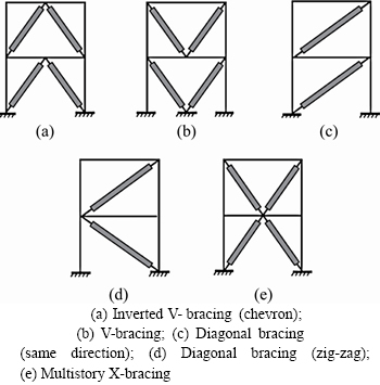
Figure 3 Example of configuration [19]:
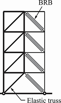
Figure 4 BRB elastic truss [20]
Despite the high-energy absorption capability and ductility of the BRB system, it has less lateral strength and less stiffness than CBF systems. Therefore, increasing lateral stiffness and strength without changing material can be accounted for an innovative success in this field. Double K (DK) formation for the BRB system (see Figure 5) can be utilized to overcome the defect (low strength and stiffness). This type of BRB has been investigated in a limited edition [27] for the strengthening of RC frames, which indicates its successful performance.
Due to the redacting of the brace length, it is expected that a less cross-section area of steel core will be needed than the other types of BRBs. By reducing the need for less area of steel core, naturally, less force is created in the beam and column surrounding the BRB due to the brace. Therefore, less area of steel core results in more economical than other modes of bracing.
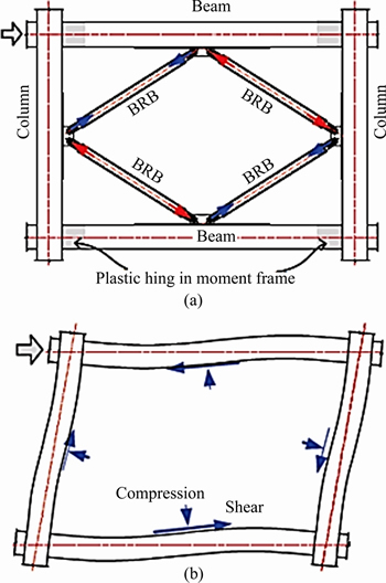
Figure 5 A schematic view of double K brace (a) and free body diagram (b) [27]
2 Method of study
To evaluate the behavior of double K bracing with BRB (DK-BRB), the system is investigated parametrically and numerically. Since the design of the bracing is dependent on the force created in the bracing member and buckling capacity of the brace member; parametrical comparison between DK and Chevron braces is performed. Besides, numerical studies were performed to evaluate DK-BRB. In a numerical study to calculate the geometric characteristics of bracing, a BRB is first designed as a single diagonal member according to the AISC 341 [28]. This model is considered a reference model that is named S-1. For this model, the area of steel core is 1200 mm2 and the volume of brace material is 6×10⁻⁶ m3. Also, for this model, IPE200 and IPB160 were designed for the beam and column, respectively. To evaluate the types of BRB braces, the length of the brace, height and specification of the beam, and the column to increase the area of steel core were taken. In subsequent models, the area of steel core was increased by 1.5, 2 and 2.5 times, to evaluate its impact on structural behavior. To compare the behavior of the brace, the volume of bracing material was kept constant but the type of brace has changed. The design in a way is done to keep constant the geometric characteristics, but just the geometry of the brace is changed. Therefore, by changing the geometric model of the brace in the form of Chevron and DK, the overall behavior of the system will be discussed.
3 Evaluation of parameters of designing double K system
Since Chevron braces have a better performance than single diagonal braces in parametric comparison, the Chevron and DK braces are compared. In Figure 6, the geometric characteristics of the BRB brace are schematically shown for the Chevron and DK braces. By analyzing the structure, it can be seen that axial force created in the brace (in both types of braces) due to the lateral load is as follows:

 (1)
(1)

 (2)
(2)
where NChevron and NDouble-Kare the axial forces of Chevron BRB and double-K brace, respectively; P is the lateral load and α is the angle between the BRB brace with the horizon as shown in Figure 6.
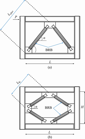
Figure 6 Geometric properties of braces
 and
and 
 so
so  and
and  therefore,the ratio of forces created, Nratio, is
  as shown in Figure 7.
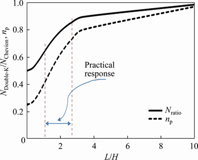
Figure 7 Parametrical comparison of BRB types
Considering that the axial and lateral capacity of the braces in addition to the cross-section (for complete submission) is depending on the buckling capacity, the buckling capacity Pe is based on the AISC code:
 (3)
(3)
Since the boundary conditions of both braces are the same, the K is equal for both of them. Thus, the ratio np of the buckling capacity of the DK brace to the Chevron brace is depicted in Figure 7.
 (4)
(4)
Figure 7 shows clearly that the axial force created in the DK brace is less than that in the Chevron brace. Force limited comparison shows that the force generated in a DK brace is 0.5-1 times the force generated by a Chevron brace. In its practical range, the ratio under L/H=1-2.50 varies from 0.63 to 0.84. That means, by increasing the span length, the force generated in the DK brace increases. Therefore, the force created in the DK brace is between 37% and 16% for practical aspects, less than the Chevron brace, so the same amount of materials will be less consumed.
Because in DK brace, the length of the brace decreases, its capacity is expected to increase. So, with less amount of materials, the required capacity can be achieved. This makes the plan more economic. Referring to Figure 7, it is obvious that the axial force created in the DK brace is less than that of Chevron. A comparison of forces shows that the force generated in a DK brace is 0.25 to 1 times more than the force generated by a Chevron brace. In its practical range, the ratio under L/H=1-2.50 varies from 0.4 to 0.7. That is, by increasing the span length, the force generated in the DK brace increases. Therefore, the force created in a DK brace is between 60% and 30%, which is less than the Chevron brace for practical aspects.
4 Numerical study
4.1 Models
Based on Eqs. (6) and (8), it is expected that Double-K BRB exposes a better performance than single diagonal BRB and Chevron BRB. To assess the expectation, some finite element (FE) models are designed. Therefore, numerical models have been listed in Table 1. The model’s name consists of two parts; one letter and one number. The letters D, C, S represent single diagonal braces, Chevron braces, and DK braces, respectively, as illustrated in Figure 8. The second part of each name stands for thickness of steel core in cm. In all models, the IPB160 with a length of 3 m for the column and an IPE200 with a length of 4 m for the beam is used. Figure 8 shows a schematic view of numerical models. Since the boundary frame for all models are the same, the internal force due to BRBs could be compared.
4.2 Material properties
In this paper, ABAQUS software is used to analyze the FE models. An important and significant thing about the definition of material in the range of plastic for this software is that the results of the tensile test, called stress and engineering strain, or the nominal values should convert to real stress and strain, then introduce to the software. Due to this fact that in ABAQUS software, to determine the properties of plastic materials, we need to use the real stress and strain of plastic. We convert the following relationships to the transformation of nominal characteristics into real properties and then convert them to the software.
 (5)
(5)
 (6)
(6)
Table 1 Numerical designed models
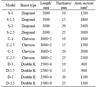
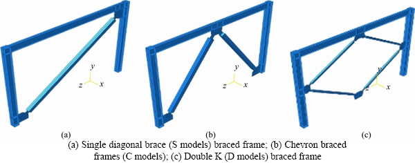
Figure 8 Schematic view of numerical models:
 (7)
(7)
where σtrue and εtrue are real stress and real strain, respectively; σn and εn are respectively nominal stress and nominal strain; εplastic is the value of the strain of plastic; σv is the yield stress; and E is the elastic modulus.
In this article, ASTM A36 steel is used for all steel components. In this steel, the tensile yield is 240 MPa; the rupture stress is 370 MPa and the modulus of elasticity is equal to 200 GPa. Also, the von-Misses benchmark is chosen as an acceptable benchmark with a suitable precision for assessing the delivery of components.
4.3 Verification of numerical results
In order to verify FE results, an experimental tested model was selected. Figure 9 shows details of experimental test. For FE modeling, materials properties as well as geometric details were considered according to the experimental properties. Based on the experimental test report, yield stress and ultimate stresses of core and tube of concrete are 235 and 370 MPa that they were used in FE modeling. Also, the concrete with compression strength of 30 MPa has been used between the steel core and tube that a same concrete is modelled in FE analysis. Also, boundary condition of FE model was selected according to the experimental setup.

Figure 9 Details of tested BRB specimen (Unit: cm) [29]
Figure 10 illustrates the experimental setup that was modeled using FE method. Two ends of brace are supported pined that is matched with a real BRB brace installed in structure. To create the pin supported in FE model, displacement in three degrees of freedom was districted but rotation did not district. Since the BRB in fact is loaded axially, the experimental specimen was applied axial loading along to the axial direction of brace.
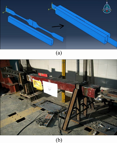
Figure 10 Finite element modeling (a) and experimental test setup (b) [29]
FE modeling has measured the stress and fracture as the same as the experimental test. The results are compared in Figure 11, exhibiting a high convergence between FE results and experimental test.
Since pushover analysis is used in this paper, the monotonic response curve of the experimental test and FE results are compared to evaluate the accuracy of FE results. These curves are derived from the peak point of the hysteresis curve of the experimental test. In Figure 12, the monotonic curves of experimental and numerical results are compared, indicating a good agreement between FE results with experimental results. Both curves are matched in the linear zone (stiffens). There is only 2.3%, 2.5%, and 3% difference between FE with the experimental result to calculate ultimate strength, energy absorption, and stiffness.
4.4 Definition of seismic behavior parameters
To estimate seismic parameters, the actual load-displacement response curves are usually idealized as illustrated in Figure 13. This idealization is based on the following assumptions and definitions:
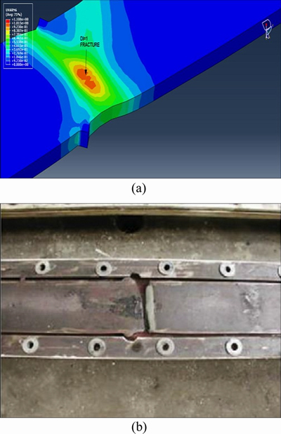
Figure 11 Finite element modeling (a) and experimental test (b) [29]
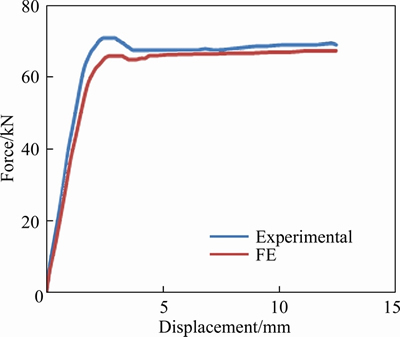
Figure 12 Comparison of experimental result with FE results
1) The maximum displacement of the structure, △max, will be considered based on the requirements of the local regulations.
2) The ultimate strength, Fu, is the maximum base shear as shown in Figure 13.
3) The elastic stiffness, K, is equal to the initial slope of the load-displacement curve, K=Fu/△y.
4) Energy absorbed by the system, E, is equal to the closed area under the load-displacement curve.

Figure 13 Idealization of load-displacement curve of structures [30]
5 Results and dissuasion
5.1 Pushover curves
The pushover curve contains valuable information about structure performance. The structural parameters can be calculated based on the pushover craves. Besides, to estimate the overall behavior of the structure, seismic parameters are obtained from the simplification of this curve. For this purpose, in Figure 14, the pushover curve of numerical models is plotted. These curves show that the behavior of the system relatively improves by increasing the area of the steel core. It also can be seen that braces of group D have better behavior than those of S and C braces. Therefore, by observing these curves, the function of group D braces is obvious in comparison to other braces.
To compare the behavior of these braces, in Figure 15, the pushover curve and the stiffness curve of the models are compared. A comparison of types of braces in Figure 15 shows that D braces have much better behavior than other systems in the nonlinear region. So, we can expect that final strength will be much better in energy absorption for this system. However, the stiffness comparison in the elastic and non-elastic regions shows that although the DK system has less stiffness in the elastic region, it has a much less dropping of stiffness than other systems. In very low drifts about 0.10%, the stiffness of this system is less than other systems and in the range of 0.10% to 0.15%, stiffness is matching together. Then this system has a lower dropping stiffness compared to the S and C systems, and from 0.15% to 1.5%, the stiffness of the D system is much higher than that of the other systems. From the drift of 0.15%, the stiffness of both systems C and S matches with each other. Of course, after the drift of 1.5%, the stiffness of the systems is matching. In the following sections, seismic parameters are discussed in detail.
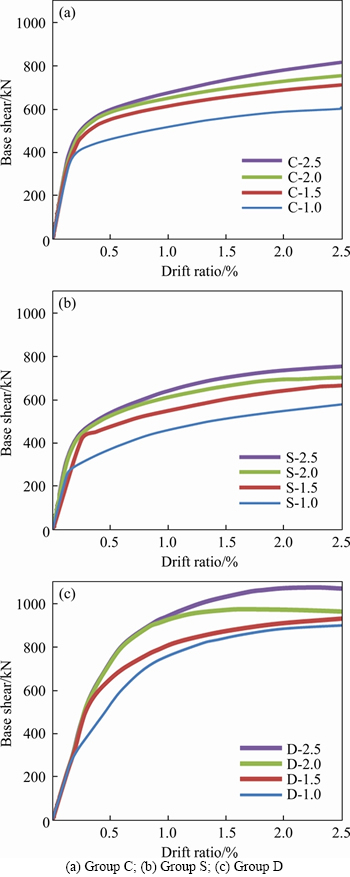
Figure 14 Pushover curves of numerical models:
5.2 Stiffness
Stiffness is the most important parameter for controlling drift and drift ratio. As the stiffness increases, the drift of the structure decreases and as a result, the secondary moments decrease. Structural stiffness shortage results from an increase in secondary moments due to the effects of P-△, which can lead to destruction in the structure. As the structure enters into the nonlinear region, the stiffness of the structure decreases. As much as the stiffness is less, the system has a better function. When stiffness dropping is less, the impact of P-△ on the system decreases. For this purpose, in Figure 16, the stiffness graph is plotted against the drift.

Figure 15 Curve of pushover (a) and stiffness (b) versus drift ratio
Figure 16 shows that however increasing the area of the steel core increases the initial stiffness (elasticity), it does not have a significant effect on non-elastic stiffness. Such a situation is true in all systems. In the previous section, in the case of comparison of non-elastic stiffness, Figure 16, systems were discussed, such a situation by increasing the thickness of the steel core is acceptable. In other words, by increasing the thickness of the steel core, the stiffness dropping of the D system is always much lower than the other systems, although the elastic stiffness is less than the other systems, shown in Figure 15 as a bar graph.
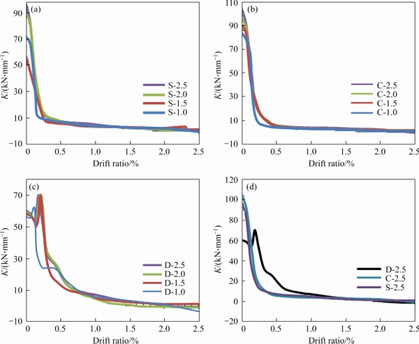
Figure 16 Comparison of stiffness curves of numerical models
Another advantage of the Double-K bracing system is that the stiffness of the system is much better than other systems, Figure 17 clearly shows that in the final drift of the double-K system, the situation is much better than others.
5.3 Ultimate lateral strength
The ultimate strength of any seismic system is one of the important parameters for coping with earthquake forces. Therefore, to evaluate this parameter in Table 2, the system’s lateral resistance is listed, and further clarity is shown in Figure 18 as a bar graph. Comparison of the results of this table shows that by increasing the area of the steel core the lateral resistance also increases. The S-2.5, C-2.5, and D-2.5 models have a core area 2.5 times more than the S-1, C-1, and D-1 models. Comparison of the results of these models shows that by increasing the area of the steel core, the lateral resistance of S, C, D systems increases to 19%, 34% and 30%, respectively. The increase of the lateral strength of the C, S systems due to the increase in the steel core is more than D.
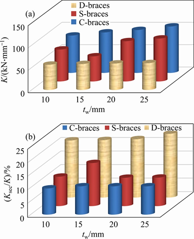
Figure 17 Comparison of stiffness of numerical models
The comparison of the lateral strengths of the various systems, listed in the fourth column of Table 2, shows that the ultimate strength of the system C is about 4% to 8% higher than system S but by changing the S system to K system, the lateral resistance of the system increases by 30% to 48%, which is very significant. Therefore, using the D system is more economic and more secure due to the need for resistance.
Table 2 Ultimate strength of numerical models
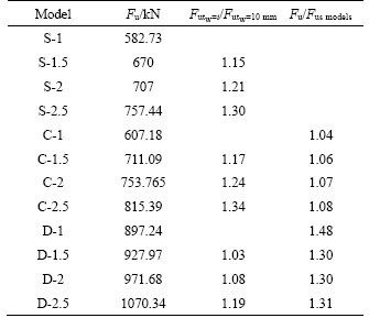
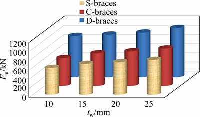
Figure 18 Ultimate strength diagram
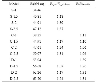
5.4 Energy absorption
One of the most important seismic parameters of any structure is its energy absorption. As the structure has more energy absorption, the earthquake will suffer less force. Therefore, structures with higher energy absorption will show better function during an earthquake. To estimate the ability of energy absorption, Figure 19 and Table 3 show the energy absorption of numerical models.
By increasing the area of the steel core, energy absorption for S systems increases from 18% to 37%, and the energy absorption for C and D systems is from 31% to 17% and from 24% to 7%, respectively. Comparison of the lateral strength of the various systems listed in the fourth column of Table 3 shows that the ultimate strength of the C system is 6%-11% higher than the S system, but by changing the S system to the K system, energy absorption increases by 26% to 31%, which is very significant. Therefore, the use of the D system is more economic and more secure due to the need for resistance.
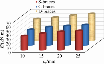
Figure 19 Energy absorption diagram
Table 3 Energy absorption of numerical models
5.5 Effect of braces on column behavior
In Figure 20, the columns’ yielding status is displayed for three types of BRB models (S-models, C-models, and D-models according to the definition in Figure 8). As shown in this figure, in the base models, the plastic hinge is formed at bottom of the column only for C-models. For all thickness of the core, the stresses of the C models are much more severe than other systems. Although in the S-models and D-models with a low thickness of core, no plastic hinges are formed, by increasing the area of the steel core, the columns are led to the formation of plastic hinge.
In S-model no hinge is formed up to increasing of core thickness equal to 25 mm (increasing of core thickness 2.5 times that benchmark model). But in D-model no hinge is formed up to increasing of core thickness equal to 15 mm (increasing of core thickness 1.5 times that of benchmark model). Therefore, it is concluded that the D-model is more sensitive than S-model in hinge formation due to increase of core thickness.

Figure 20 Yielding states of stress in columns
6 Conclusions
A comparison of three configuration states in single-diameter, Chevron, and DK systems in different aspects, shows that the DK system has a better function and is more economic than other configurations.
By increasing the steel core area, the system behavior relatively improves. Comparison of the results shows that by increasing the area of the steel core, the lateral resistance for S, C, D systems increases up to 19%, 34% and 30%, respectively. Also, by increasing the steel core area, energy absorption for S systems increases from 18% to 37%; the energy absorption increasing for C and D systems is 31%-17% and 24%-7%, respectively. Comparison of the lateral strengths of various systems, shows that the final strength of system C is about 6% to 11% higher than S system, but by changing the S system to the K system, the energy absorption system increases by 26% to 31%, which is very significant.
Although the increase in the area of the steel core increases the initial stiffness (elasticity), it does not have a significant effect on the non-elastic stiffness. Therefore, even by increasing the area of the steel core, the stiffness drop in the non-elastic region shows a clear trend.
Although the DK system has less elastic stiffness than other BRB configurations, its dropping stiffness is much lower in the non-elastic region. In very low drifts to about 0.10%, the stiffness of this system is lower than other systems, and in the range of 0.10% to 0.15%, the stiffness is matching together. Then the system has less dropping stiffness compared to the S and C systems, and from 0.15% to 1.50%, the stiffness of the D system is much higher than the other systems. From the gravity 0.15%, the stiffness of both systems C and S matches with each other. Of course, from 1.5% to 1.5%, the stiffness of the systems is matching.
Comparison of the lateral strength of the various systems shows that the ultimate strength of the C system is 4% to 8% higher than S, but by changing S to the K system, the lateral strength of the system increases by 30% to 48%, which is very significant. Therefore, the use of the D system is more economic and more secure due to the need for strength.
Contributors
The overarching research goals were developed by Ali GHAMARI and Hadi HAERI. Amir JOHARI NAEIMI and Zohreh NAJMI analyzed the calculated results. The initial draft of the manuscript was written by Ali GHAMARI and Hadi HAERI. Vahab SARFARAZI edited the draft of the manuscript.
Conflict of interest
The awthors declare that they have no conflict of interest.
References
[1] MAZZOLANI F M, CORTE G D, D'ANIELLO M. Experimental analysis of steel dissipative bracing systems for seismic upgrading [J]. Journal of Civil Engineering and Management, 2009, 15(1): 7-19. DOI: 10.3846/1392-3730. 2009.15.7-19.
[2] GUERRERO H, ESCOBAR J A, TERAN-GILMORE A. Experimental damping on frame structures equipped with buckling-restrained braces (BRBs) working within their linear-elastic response [J]. Soil Dynamics and Earthquake Engineering, 2018, 106: 196-203. DOI: 10.1016/j.soildyn. 2017.12.028.
[3] WENG Yuan-tao, TSAI K C, CHEN P C, CHOU C C, CHAN Ya-ran, JHUANG S J, WANG Y Y. Seismic performance evaluation of a 34-story steel building retrofitted with response modification elements [J]. Earthquake Engineering & Structural Dynamics, 2009, 38(6): 759-781. DOI: 10.1002/eqe.865.
[4] CORTE G, D’ANIELLO M, MAZZOLANI F. Seismic upgrading of RC buildings using buckling restrained braces: Full-scale experimental tests [C]// Proceedings of the XX Italian Congress on Steel and Composite Structures. Ischia, Italy, 2005.
[5] CHOI H, KIM J. Energy-based seismic design of buckling-restrained braced frames using hysteretic energy spectrum [J]. Engineering Structures, 2006, 28(2): 304-311. DOI: 10.1016/j.engstruct.2005.08.008.
[6] DELLA CORTE G, LANDOLFO R, MAZZOLANI F M. Displacement-based seismic design of braced steel structures [J]. Steel Construction, 2010, 3(3): 134-139. DOI: 10.1002/ stco.201010019.
[7] MALEY T J, SULLIVAN T J, CORTE G D. Development of a displacement-based design method for steel dual systems with buckling-restrained braces and moment-resisting frames [J]. Journal of Earthquake Engineering, 2010, 14(sup1): 106-140. DOI: 10.1080/13632461003651687.
[8] LU Jun-kai, WU Bin, MEI Yang. Buckling mechanism of steel core and global stability design method for fixed-end buckling-restrained braces [J]. Engineering Structures, 2018, 174: 447-461. DOI: 10.1016/j.engstruct.2018.07.024.
[9] IWATA M, KATO T, WADA A. Buckling-restrained braces as hysteretic dampers [C]// Proceedings of STESSA 2000. Montreal, Quebec, 2000: 21-24.
[10] TSAI C, LAI W, HWANG C, LIN L, WENG T. Research and application of double-core buckling restrained braces in Taiwan [C]// Proceedings of the 13th World Conference on Earthquake Engineering. Canada, 2004.
[11] WATANABE A, HITOMI Y, SAEKI E, WADA A, FUJIMOTO M. Properties of brace encased in buckling-restraining concrete and steel tube [C]// Proceedings of 9th World Conference on Earthquake Engineering, 1988: 719-724.
[12] WADA A, SAEKI E, TAKEUCHI T, WATANABE A. Development of unbonded brace [M]. Column: Nippon Steel Publication, 1989.
[13] XIE Qiang. State of the art of buckling-restrained braces in Asia [J]. Journal of Constructional Steel Research, 2005, 61(6): 727-748. DOI:10.1016/j.jcsr.2004.11.005.
[14] OZBULUT O E, HURLEBAUS S. Application of an SMA-based hybrid control device to 20-story nonlinear benchmark building [J]. Earthquake Engineering & Structural Dynamics, 2012, 41(13): 1831-1843. DOI:10.1002/eqe.2160.
[15] XU Long-he, FAN Xiao-wei, LI Zhong-xian. Development and experimental verification of a pre-pressed spring self-centering energy dissipation brace [J]. Engineering Structures, 2016, 127: 49-61. DOI:10.1016/j.engstruct.2016.08.043.
[16] DONG Hui-hui, DU Xiu-li, HAN Qiang, HAO Hong, BI Kai-ming, WANG Xiao-qiang. Performance of an innovative self-centering buckling restrained brace for mitigating seismic responses of bridge structures with double-column piers [J]. Engineering Structures, 2017, 148: 47-62. DOI: 10.1016/ j.engstruct.2017.06.011.
[17] ZHOU Z, XIE Q, LEI X C, HE X T, MENG S P. Experimental investigation of the hysteretic performance of dual-tube self-centering buckling-restrained braces with composite tendons [J]. Journal of Composites for Construction, 2015, 19(6): 04015011. DOI: 10.1061/(asce)cc.1943-5614.0000565.
[18] KERSTING R A, FAHNESTOCK L A, LOPEZ W A. Seismic design of steel buckling-restrained braced frames: A guide for practicing engineers[R]. National Institute of Standards and Technology, 2016. DOI: 10.6028/nist.gcr.15-917-34.
[19] ATLAYAN O, CHARNEY F A. Hybrid buckling-restrained braced frames [J]. Journal of Constructional Steel Research, 2014, 96: 95-105. DOI: 10.1016/j.jcsr.2014.01.001.
[20] TREMBLAY R, PONCET L. Seismic performance of concentrically braced steel frames in multistory buildings with mass irregularity [J]. Journal of Structural Engineering, 2005, 131(9): 1363-1375. DOI: 10.1061/(asce)0733-9445(2005) 131:9(1363).
[21] BOUWKAMP J, VETR M G, GHAMARI A. An analytical model for inelastic cyclic response of eccentrically braced frame with vertical shear link (V-EBF) [J]. Case Studies in Structural Engineering, 2016, 6: 31-44. DOI: 10.1016/ j.csse.2016.05.002.
[22] VETR M G, GHAMARI A, BOUWKAMP J. Investigating the nonlinear behavior of eccentrically braced frame with vertical shear links (V-EBF) [J]. Journal of Building Engineering, 2017, 10: 47-59. DOI: 10.1016/j.jobe.2017.02. 002.
[23] VETR M G, GHAMARI A. Experimentally and analytically study on eccentrically braced frame with vertical shear links [J]. The Structural Design of Tall and Special Buildings, 2019, 28(5): e1587. DOI: 10.1002/tal.1587.
[24] LI Ran, SHU Gan-ping, LIU Zhen, GE Han-bin. Research and development of an innovative self-centering energy dissipation brace [J]. The Structural Design of Tall and Special Buildings, 2018, 27(15): e1514. DOI: 10.1002/tal.1514.
[25] ZHAO Jun-xian, CHEN Ruo-bing, ZHOU Yun, YU Hai-chao, KONG Yu-wen, WANG Zhan, DOU Miao-yuan, SHI Yi-fan. Effect of gusset connection configurations on frame-gusset interaction in steel buckling-restrained braced frame [J]. The Structural Design of Tall and Special Buildings, 2019, 28(5): e1584. DOI: 10.1002/tal.1584.
[26] QIAO Sheng-fang, HAN Xiao-lei, ZHOU Ke-min. Bracing configuration and seismic performance of reinforced concrete frame with brace [J]. The Structural Design of Tall and Special Buildings, 2017, 26(14): e1381. DOI: 10.1002/tal.1381.
[27] QU Zhe, XIE Jin-zhen, WANG Tao, KISHIKI S. Cyclic loading test of double K-braced reinforced concrete frame subassemblies with buckling restrained braces [J]. Engineering Structures, 2017, 139: 1-14. DOI: 10.1016/ j.engstruct.2017.02.040.
[28] AISC 341-05. Seismic provisions for structural steel buildings [M]. Chicago, Illinois: American Institute of Steel Construction Inc., 2005.
[29] ARBABI F, TABAROK M. Experimental study of a new BRB [J]. Journal of Amirkabir Journal of Civil Engineering, 2015, 40(2): 1-157.
[30] KHALOO A, FOROUTANI M, GHAMARI A. Influence of diagonal stiffeners on the response of steel plate shear walls (SPSWs) considering crack propagation [J]. Bulletin of Earthquake Engineering, 2019, 17(9): 5291-5312. DOI: 10.1007/s10518-019-00685-2.
(Edited by YANG Hua)
中文导读
双K-BRB防屈约束支撑在侧向载荷下的行为
摘要:防屈约束支撑(BRB)是一种能有效抵抗具有高地震能量吸收能力的侧向载荷的系统。虽然防屈约束支撑已经证实具有令人满意的行为,但系统刚度不理想,它能被防屈约束支撑的配置变化抵消。为此,研究了双K-BRB(DK)防屈约束支撑的配置,以实现更合适的行为。同时,还提出了设计该系统所需的数学公式。将DK系统与其他传统BRB进行比较,结果表明,DK系统比其他传统BRB具有更好的结构性能,且更经济(需要更少的核心面积)。数值结果表明,DK系统提高了侧向极限强度、侧向非线性刚度和能量吸收能力。此外,DK配置还减少了在非线性区域中纵向产生的轴向力。材料需求的减少、在主框架中产生的力及非线性刚度的增加提高了结构的安全性。
关键词:防屈约束支撑(BRB);刚度;极限强度;延展性;支撑;能量吸收
Received date: 2020-08-24; Accepted date: 2021-01-07
Corresponding author: Hadi HAERI, PhD; E-mail: haerihadi@gmail.com; ORCID: https://orcid.org/0000-0002-5002-1497; Ali GHAMARI, Assistant Professor; E-mail: aghamari@alumni.iust.ac.ir; ORCID: https://orcid.org/0000-0003-4204-1743

