固体润滑颗粒增强铝基复合材料的高温摩擦学行为
来源期刊:中国有色金属学报(英文版)2020年第5期
论文作者:V. V. MONIKANDAN P. K. RAJENDRAKUMAR M. A. JOSEPH
文章页码:1195 - 1210
关键词:铝基混杂复合材料;高温摩擦学行为;固体润滑;变形带;动态再结晶
Key words:aluminum hybrid composites; high temperature tribological behavior; solid lubrication; deformation band; dynamic recrystallization
摘 要:通过搅拌铸造法制备AA6061-10wt.%B4C单一复合材料,Gr(Gr为石墨)颗粒含量为 2.5、5、7.5 wt.%的AA6061-10wt.%B4C-Gr 混杂复合材料,和MoS2颗粒含量为2.5、5、7.5 wt.%的AA6061-10wt.%B4C-MoS2 混杂复合材料。采用销-盘式摩擦试验机(对磨材料为EN31)研究温度对复合材料干滑动摩擦行为的影响。在30~100 °C的温度范围内,由于摩擦保护层及其固体润滑相的共同润滑作用,Gr增强和MoS2增强的混杂复合材料的磨损率和摩擦因数均下降。对磨损表面进行扫描电镜观察,结果表明,150、200和 250 °C下的磨损机制分别为重度粘着磨损、剥层磨损和磨粒磨损。透射电镜结果显示,150 °C时,混杂复合材料中形成了变形带和精细的晶体结构,分别是由严重的塑性变形和动态再结晶造成的。
Abstract: The AA6061-10wt.%B4C mono composite, AA6061-10wt.%B4C-Gr (Gr: graphite) hybrid composites containing 2.5, 5, and 7.5 wt.% Gr particles, and AA6061-10wt.%B4C-MoS2 hybrid composites containing 2.5, 5, and 7.5 wt.% MoS2 particles were fabricated through stir casting. The dry sliding tribological behaviors of the mono composite and hybrid composites were studied as a function of temperature on high temperature pin-on-disc tribotester against EN 31 counterface. The wear rate and friction coefficient of the Gr-reinforced and MoS2-reinforced hybrid composites decreased in the temperature range of 30-100 °C due to the combined lubrication offered by the wear protective layer and its solid lubricant phase. Scanning electron microscopy (SEM) observation of the worn pin surface revealed severe adhesion, delamination, and abrasion wear mechanisms at temperatures of 150, 200, and 250 °C, respectively. At 150 °C, transmission electron microscopy (TEM) observation of the hybrid composites revealed the formation of deformation bands due to severe plastic deformation and fine crystalline structure due to dynamic recrystallization.
Trans. Nonferrous Met. Soc. China 30(2020) 1195-1210
V. V. MONIKANDAN 1, P. K. RAJENDRAKUMAR2, M. A. JOSEPH2
1. Department of Production Engineering, PSG College of Technology, Coimbatore 641004, Tamilnadu, India;
2. Department of Mechanical Engineering, National Institute of Technology, Calicut 673601, Kerala, India
Received 22 February 2019; accepted 31 March 2020
Abstract: The AA6061-10wt.%B4C mono composite, AA6061-10wt.%B4C-Gr (Gr: graphite) hybrid composites containing 2.5, 5, and 7.5 wt.% Gr particles, and AA6061-10wt.%B4C-MoS2 hybrid composites containing 2.5, 5, and 7.5 wt.% MoS2 particles were fabricated through stir casting. The dry sliding tribological behaviors of the mono composite and hybrid composites were studied as a function of temperature on high temperature pin-on-disc tribotester against EN 31 counterface. The wear rate and friction coefficient of the Gr-reinforced and MoS2-reinforced hybrid composites decreased in the temperature range of 30-100 °C due to the combined lubrication offered by the wear protective layer and its solid lubricant phase. Scanning electron microscopy (SEM) observation of the worn pin surface revealed severe adhesion, delamination, and abrasion wear mechanisms at temperatures of 150, 200, and 250 °C, respectively. At 150 °C, transmission electron microscopy (TEM) observation of the hybrid composites revealed the formation of deformation bands due to severe plastic deformation and fine crystalline structure due to dynamic recrystallization.
Key words: aluminum hybrid composites; high temperature tribological behavior; solid lubrication; deformation band; dynamic recrystallization
1 Introduction
The particles reinforced metal matrix composites (MMCs) expand the scope of commercial applicability of MMC systems by providing the improved processability and affordability [1,2]. The particles reinforced aluminum matrix composites (AMCs) are the apt candidate materials for tribologically critical applications, such as pistons, piston rings, and cylinder liners [3]. The AMCs reinforced with hard ceramic particles exhibit enhanced wear resistance compared to the monolithic Al-alloys [4,5]. The increase in the addition of ceramic particles also seems to improve specific properties [6-8]. However, most of the studies have been focused on AMCs reinforced with conventional reinforcement particles (SiC and Al2O3), and studies on B4C- reinforced mono and hybrid AMCs have been limited due to the higher cost of B4C particles. It is reported that the hardness of B4C is higher than that of the conventional reinforcement, Al2O3, and the density of B4C is lower than that of the solid aluminum [9]. These factors ensure substantial improvement in the specific properties of AMCs reinforced with B4C particles. Hence, in an earlier work, MONIKANDAN et al [10] fabricated an AA6061-10wt.%B4C mono composite and reported its tribological characteristics at room temperature. Hybrid composites reinforced with solid lubricant particles and ceramic particles exhibit anti-seizure and wear-resisting properties. Thus, in two different studies, the investigators reported the tribological behaviors of AA6061-10wt.%B4C-Gr hybrid composites and AA6061-10wt.%B4C-MoS2 hybrid composites at room temperature [11,12].
The literature on the high temperature tribological studies of the AMCs is limited compared with the literature on tribological studies of AMCs at room temperature. During high temperature sliding, the wear debris accumulation leads to the formation of smooth layers, which reduced the wear rate [13]. SCIULLI and ROBINSON [14] observed that if the wear debris is not compacted to form solid layers, it may act as abrasives to induce wear damage. LIU et al [15] studied the tribological behavior of Al-Al2O3 and Al-Al2O3-CF (CF: Carbon fiber) composites in the temperature range of 25-400 °C. The study showed that the hybrid composite exhibited a lower wear rate than the mono composite. Furthermore, severe wear was observed in the temperature range of 350-400 °C for the hybrid composite whereas the mono composite showed severe wear in a comparatively low temperature range of 250- 300 °C. This phenomenon indicates that it is beneficial to adding CF in the AMCs for high temperature applications.
The addition of solid lubricant particles influences the high temperature tribological behaviors of the composites. Tribological tests at temperatures ranging from room temperature to 350 °C on Al-Si-3wt.%Gr composite led to the reduction of wear rate compared to the wear rate of the parent matrix [16]. The addition of MoS2 particles to Ni-20Cr alloys led to the decrease in friction coefficient for the temperature range between room temperature and 400 °C, and the Ni-10%MoS2 composite exhibited lower wear rate than the Ni-15%MoS2 composite [17]. ZHAN and ZHANG [18] studied the influence of Gr addition to the Cu-SiC mono composite in the temperature range of 100 to 550 °C and observed that the friction coefficient of the hybrid composite is lower than that of the mono composite. RYNIO et al [19] also indicated that the materials subjected to dry sliding undergo dynamic recrystallization with the increase in temperature. At 800 °C, they observed ultra-fine grains of the Ni-based alloy that are formed due to dynamic recrystallization.
The literatures [13-17] make it evident that the test temperatures, the content of solid lubricant particles, and the layer formation influence the tribological properties of the composites during high temperature sliding wear tests. It is noted that the studies about the effect of temperature variation on the wear behavior of hybrid composites reinforced with Gr particles and MoS2 particles as solid lubricant phase are limited. Studies about the influence of temperature variation on the crystalline structure of the composites are also lacking. Therefore, in the present study, the tribological properties of the AA6061-10wt.%B4C-Gr and AA6061-10wt.%B4C-MoS2 hybrid composites were studied at different temperatures. Furthermore, the tribological properties of the Gr-reinforced and MoS2-reinforced hybrid composites and the mono composite were compared to infer the influence of solid lubricant addition. The hybrid composites can be potential candidate materials for manufacturing automotive components that are exposed to high temperatures during service.
2 Experimental
The materials, stir casting method, tribo-test parameters, and the characterization techniques used in the study are detailed in the following sections.
2.1 Materials
AA6061 alloy (0.86 Mg, 0.67 Si, 0.21 Cu, 0.19 Fe, 0.05 Cr, 0.04 Mn, 0.018 Ti, 0.004 Zn, 0.003 B, 0.001 Pb, and the rest Al by wt.%) was used as the matrix material. B4C particles of 30 μm in average particle size (APS), Gr particles of 45 μm in APS, and MoS2 particles of 130 μm in APS were used as the reinforcements.
2.2 Stir casting
The stir casting method was used to fabricate the AA6061-10wt.%B4C mono composite, AA6061-10wt.%B4C-Gr hybrid composites containing 2.5, 5, and 7.5 wt.% Gr particles, and AA6061-10wt.%B4C-MoS2 hybrid composites containing 2.5, 5, and 7.5 wt.% MoS2 particles. The fabrication procedure of these composites is available in the previous studies [10-12]. The summary of the stir casting method is given in this section.
Figure 1 shows the schematic of the stir casting process. The stir casting of the composites was carried out in the argon atmosphere. The matrix material was melted in the furnace at 800 °C, and hydrogen dissolved in the melt was removed by adding hexachloroethane (C2Cl6) tablets. The wettability was improved by adding magnesium (1 wt.%). The preheated reinforcement particles were added gradually into the vortex formed by stirring. In the case of hybrid composites, the reinforcement particles were mixed manually in an aluminum agate mortar and pestle before preheating them in a furnace. Stirring was continued for 1500 s after the addition of the particles or particles mixture into the vortex formed in the melt, and then the composite melt was poured into the preheated mold for solidification in atmospheric conditions.
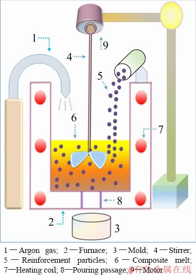
Fig. 1 Schematic diagram of stir casting process
The micrograph and XRD spectrum of the mono composite are available in an earlier study [10]. The metallographs and XRD spectra of Gr-reinforced hybrid composites are available in earlier studies [11,20], and the metallographs and XRD spectra of MoS2-reinforced hybrid composites are also accessible in a previous study [12].
2.3 Tribo-tests
Composite pins of 27 mm in height and 8 mm in diameter were tested as per ASTM G99―17 standard by employing a pin-on-disk tribotester (Magnum Engineers, TE-165-SPOD) equipped with a high temperature heating element. Dry sliding wear tests were conducted at the temperatures of 30 (ambient temperature), 50, 100, 150, 200, and 250 °C. During the tests, the track radius, sliding speed, sliding distance, and applied load were kept constant at 0.1 m, 1.5 m/s, 600 m, and 30 N, respectively. The atmospheric pressure and relative humidity throughout the tests, respectively, were 1.013×10⁵ Pa and (70±5)%.
Before each test, the temperature of the heating element was raised to the required test temperature, and the specimen was allowed to equilibrate for 20 min to ensure uniform temperature distribution. EN 31 bearing steel disk (0.99 C, 0.35 Mn, 0.25 Si, 0.025 P, 0.025 S, 1.40 Cr, 0.1 Mo, 0.25 Ni, 0.35 Cu, and the balance Fe by wt.%) was used as the counterface. EN 31 steels were commonly used to fabricate automotive components that possessed wear-resistance characteristics [21]. Furthermore, they were used for engineering applications where high hardness is the prime requirement [22]. The hardness and surface roughness of the disk were HRC 65 and 0.1 μm, respectively. The tribo-couple was washed thoroughly with acetone before each test. A precision weighing balance (Sartorius, Secura 613-1S) of resolution 0.1 mg was used to quantify the wear loss. The wear rate was calculated from the mass loss measurements using the formula W=Δm/S, where W is the wear rate in μg/m, Δm is the difference in mass of the pin before and after the test in μg, and S is the sliding distance in m. The friction coefficient was calculated as the ratio of tangential friction force to the normal force. The tests were repeated three times, and the mean of the three readings was used for plotting the graphs. The error bars show the standard deviation.
2.4 Characterization
The worn pin surfaces were characterized using scanning electron microscopy (SEM, Hitachi, SU6600 and Jeol, JSM-6390LV), electron dispersive X-ray spectroscopy (EDS, Horiba, EMAX 137 eV), high-resolution transmission electron microscope (HRTEM, Jeol, JEM-2100), and electron backscatter diffraction (EBSD, FEI, Quanta 3D, FEG-SEM). For EBSD studies, the specimen was electropolished using a mixture of methanol and perchloric acid (90:10, volume ratio).
3 Results and discussion
Experiments using the pin-on-disk tribotester were conducted up to 250 °C to evaluate the high temperature tribological properties of the mono composite and Gr- and MoS2-reinforced hybrid composites.
3.1 Effect of temperature on wear rate and morphology
The variation curves of wear rate are plotted as a function of temperature as shown in Fig. 2. Figure 2(a) shows the wear rate of the mono composite, 2.5 wt.% Gr hybrid composite, and 2.5 wt.% MoS2 hybrid composite as a function of temperature. Figure 2(b) shows the wear rate of the mono composite, 5 wt.% Gr hybrid composite, and 5 wt.% MoS2 hybrid composite as a function of temperature, and Fig. 2(c) shows the wear rate of the mono composite, 7.5 wt.% Gr hybrid composite, and 7.5 wt.% MoS2 hybrid composite as a function of temperature. For the mono composite and Gr- reinforced and MoS2-reinforced hybrid composites studied, the wear rate decreases with increase in temperature up to 100 °C (Figs. 2(a), (b), and (c)). In the case of the Gr-reinforced and MoS2- reinforced hybrid composites, this phenomenon is attributed to the combined lubrication offered by the wear protective layer and its solid lubricant phase.
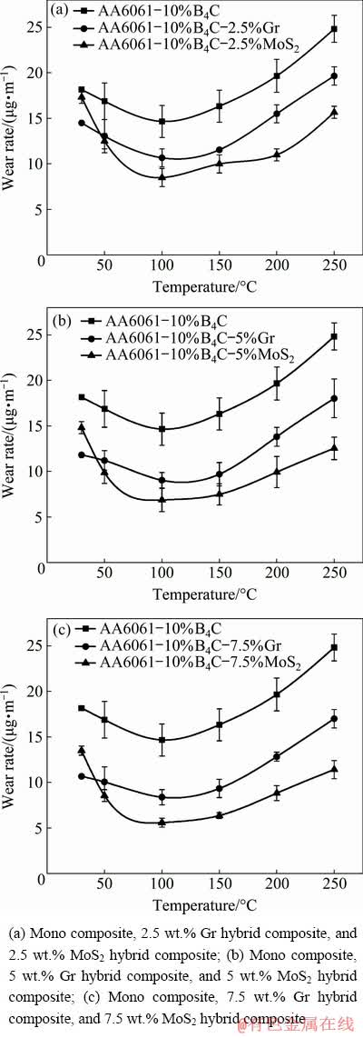
Fig. 2 Variation of wear rate as function of temperature
As the sliding is initiated, material from the pin surface is sheared off by the counterface asperities, leading to the transfer of pin material onto the counterface. The increase in temperature causes the complete or partial oxidation of the matrix material debris. As sliding continues, this debris gets comminuted into fine sized particles and gets agglomerated between the pin surface and the counterface. Figure 3(a) shows the schematic diagram of the presence of fine sized and agglomerated wear debris between 7.5 wt.% Gr hybrid composite pin surface and the counterface. During sliding, the solid lubricant particles get squeezed out from the pin material and smeared on the contact surfaces (Fig. 3(b)) [23]. The protruding B4C particles groove the counterface, leading to the formation of oxidized iron (Fe) debris. Figure 3(b) shows the schematic diagram of part of the counterface material on the verge of getting detached as debris (the region marked with dotted circle). As the sliding continues, the B4C particles are fractured into fine sized particles due to the formation of microcracks (Fig. 3(b)) [24]. The agglomerated and fine sized debris (fully and partially oxidized) of the matrix material gets mixed up with the smeared solid lubricant particles, fine sized B4C particles, and oxidized Fe debris and transferred back and forth between the contact surfaces. This phenomenon leads to the formation of a wear protective layer as shown in the schematic diagram in Fig. 3(c).
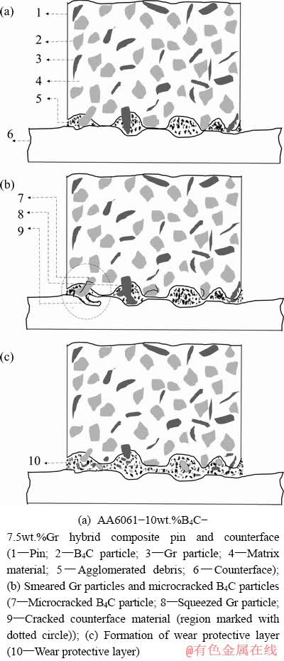
Fig. 3 Schematic representations of formation of wear protective layer at 100 °C
The formation of the wear protective layer depends on the depth of sliding grooves on the worn pin surface since only the deeper sliding grooves retain the debris on the wear track [25]. The counterface used in this study forms fairly deep sliding grooves on the worn pin surface to trap the debris on the wear track. Figure 4(a) shows the SEM image of the debris of the 5 wt.% Gr hybrid composite that is trapped in the sliding groove at 50 °C, and Fig. 4(b) shows the high magnification micrograph of the region marked with dotted circle in Fig. 4(a). As the temperature increases to 100 °C, the debris gets compacted and sintered. Figure 5 shows SEM image of the wear debris of 5 wt.% Gr hybrid composite after the compaction. Due to compaction, the loose wear debris (Fig. 4(b)) becomes closely-compacted as shown in Fig. 5. The back and forth transfer of the debris and its compaction and sintering lead to the formation of a smoothly buffed wear protective layer rich in solid lubricant phase. It is noted that the sintering rate increases with the increase in temperature, which supports the formation of the wear protective layer [26]. The SEM images of the wear protective layers formed on the worn pin surface of 7.5 wt.% Gr hybrid composite and 7.5 wt.% MoS2 hybrid composite at 100 °C are shown in Fig. 6(a) and (b), respectively.
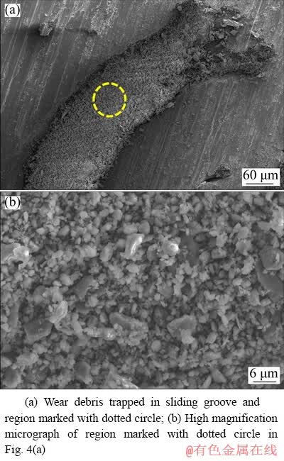
Fig. 4 SEM images of 5 wt.% Gr hybrid composite at 50 °C
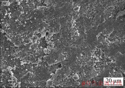
Fig. 5 SEM image showing compacted wear debris of 5 wt.% Gr hybrid composite at 100 °C
The constituents of the wear protective layer of 7.5 wt.% Gr hybrid composite can be seen in Fig. 6(a). Figure 6(b) shows the constituents of the wear protective layer of 7.5 wt.% MoS2 hybrid composite.
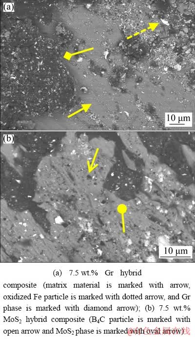
Fig. 6 SEM images (BSE detector) of wear protective layer formed at 100 °C
The wear protective layer formed on the worn pin surfaces of the Gr-reinforced and MoS2- reinforced hybrid composites prevents direct metallic contact of the tribo-couple. The combined action of the wear protective layer and the solid lubricant phase provides lubrication at the interface of the contact surfaces, leading to a decrease in wear rate for temperatures up to 100 °C. This phenomenon conforms with the observation of RAJARAM et al [16] who studied the tribological behavior of Al-Gr composites and attributed the decrease in wear rate with increase in temperature to the combined lubrication offered by the glazing layer and the graphite film present on the contact surfaces.
The chemical analysis of the wear protective layer of 7.5 wt.% Gr hybrid composite was carried out using EDS (22.64 C, 10.29 O, 0.67 Mg, 14.64 Fe, 0.28 Si, and 51.48 Al by wt.%). It is seen that the Fe content in the wear protective layer is 14.64 wt.%, which is higher than that present in the AA6061 matrix material due to an alloying addition. The flow of the debris between the elements of the tribo-couple leads to the transfer of oxidized Fe debris from the counterface to the worn pin surface. Primarily, the content of Fe controls oxidation. The Fe oxides form faster than the oxides of the other alloying additions of the tribo-couple [27]. Hence, the counterface undergoes faster oxidation during sliding since Fe is its primary constituent. Within the temperature range of 30-100 °C, the rapid oxidation of the Fe debris of the counterface bolsters the full-fledged formation of wear protective layer. The increase in the addition of solid lubricant particles in the hybrid composites improves the lubricity of the wear protective layer, leading to the decrease in wear rate. Figure 7 shows this phenomenon at 100 °C.
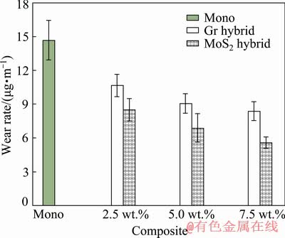
Fig. 7 Comparison plots for wear rates of mono composite, Gr-reinforced and MoS2-reinforced hybrid composites at 100 °C
In the case of mono composite, the wear protective layer formed on the worn pin surface (Fig. 8) causes a decrease in wear rate up to 100 °C by providing solid lubrication. The wear protective layer is formed in a similar manner as that of the hybrid composites (i.e., the oxidized and partially oxidized agglomerated debris getting compacted and sintered, leading to its formation). However, the wear rate of the mono composite is higher than that of the Gr-reinforced and MoS2-reinforced hybrid composites due to the absence of solid lubricant particles.
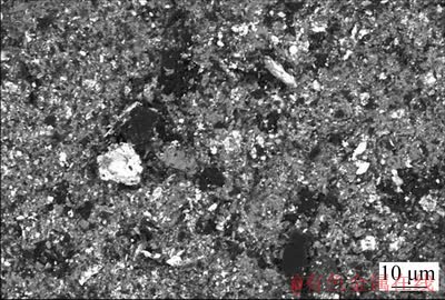
Fig. 8 SEM image (BSE detector) of wear protective layer formed on worn pin surface of mono composite at 100 °C
As the temperature of the Gr-reinforced and MoS2-reinforced hybrid composites increases further to 150 °C, cracks originate at the interface of the wear protective layer and the bulk pin due to the substantial difference in their mechanical properties. The cracks propagate onto the surface, and Fig. 9(a) shows SEM image of the crack (marked with arrow) present on the wear protective layer of the 7.5 wt.% Gr hybrid composite. The layer breaks and gets loose, and the debris is scattered on the worn pin surface, as shown in Fig. 9(b). PAUSCHITZ et al [25] observed a similar phenomenon for the MA 253 alloy, where the composite layer formed on the worn pin surface failed at the interface, leading to an increase in wear rate. Furthermore, BLAU [28] reported that with an increase in temperature, the mechanical properties of the surface oxide layers influence the wear and surface damage of the contact surfaces. Hence, it is inferred that the contact between the tribo- couple asperities is now established due to the disintegration of the wear protective layer, and the increase in temperature to 150 °C softens the matrix material, leading to its plastic flow. The plastic flow causes the bulk transfer of 7.5 wt.% Gr hybrid composite pin material to the counterface as shown in Fig. 10(a). Figure 10(b) shows SEM image of the worn pin surface of 7.5 wt.% Gr hybrid composite that depicts the plastic flow in a wavy appearance, and this appearance is generated due to the overlapping of the plastically flowed material.
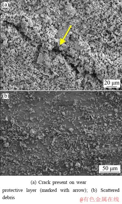
Fig. 9 SEM images of worn pin surfaces of 7.5 wt.% Gr hybrid composite at 150 °C
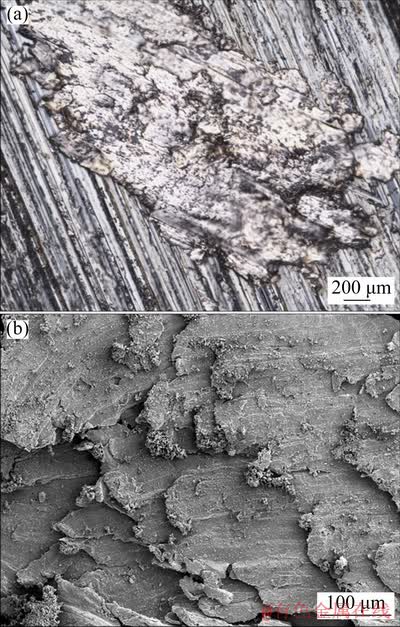
Fig. 10 OM image showing worn pin material of 7.5 wt.% Gr hybrid composite adhered to counterface (a) and SEM image showing plastic flow on worn pin surface of 7.5 wt.% Gr hybrid composite (b) at 150 °C
The chemical analysis of the worn pin surface was carried out by using EDS (2.00 C, 0.54 Cr, 0.67 Si, 0.8 Mg, and 95.99 Al by wt.%). The absence of Fe and O indicates that there is no formation of wear protective layer. It is noted that the plastic flow masks the supply of solid lubricant particles to the contact interface. The plastic flow and absence of wear protective layer lead to the induction of severe adhesion. Thus, as the temperature of the Gr-reinforced and MoS2- reinforced hybrid composites increases to 150 °C, severe adhesion is the operating wear mechanism. LIU et al [15] observed severe adhesion at 200 °C for the matrix alloy and Al-Al2O3-CF hybrid composite and termed the pattern seen on the severe adhesion induced worn pin surface, as shear wedge pattern. This pattern is similar to that observed on the worn pin surface of the 7.5 wt.% Gr hybrid composite (Fig. 10(b)). The severe adhesion causes damage to the worn pin surface in the form of a shallow crater of considerable length. The crater is formed as the result of cracks propagating and joining each other and the material getting detached in the form of irregular-shaped wear debris. Figure 11 shows the shallow crater formed on the worn pin surface of the 7.5 wt.% MoS2 hybrid composite at 150 °C. Figure 11 has been generated by connecting consecutive micrographs to get an integrated and continuous image.
Distinct and continuous sliding grooves (marked with arrow), small cracks (marked with dotted arrow), and cross-hatchings (marked with open arrows) are visible. Figure 12(a) shows SEM image of the irregular-shaped wear debris of the 7.5 wt.% MoS2 hybrid composite. The region marked with the dotted circle in Fig. 12(a) is magnified and shown in Fig. 12(b), which illustrates cross-hatchings (marked with arrow). Figure 12(c) shows another high magnification micrograph of Fig. 12(a), illustrating a hairline crack (marked with arrow). The formation and propagation of the hairline cracks, such as the one shown in Fig. 12(c), cause the detachment of material from the pin surface, leading to the generation of the shallow crater.
As the temperature increases from 150 to 200 °C, the strength of the matrix material decreases, leading to the subsurface plastic deformation [18]. The subsurface plastic deformation generates pile-ups of dislocations at the subsurface. Subsequently, voids are formed, and they coalesce to produce cracks. As cracks reach the critical length, the pin material is delaminated to produce platelet-shaped wear debris [29]. Thus, as the temperature increases from 150 to 200 °C, the delamination wear is induced, which leads to the increase in wear rate of the hybrid composites. Figures 13(a) and (b) show SEM images of the delaminated worn pin surface and platelet-shaped wear debris of 2.5 wt.% MoS2 hybrid composite at 200 °C, respectively.
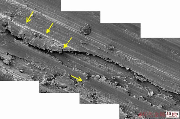
Fig. 11 SEM images of shallow crater formed on worn pin surface of 7.5 wt.% MoS2 hybrid composite at 150 °C (sliding grooves (marked with arrow), small crack (marked with dotted arrow), and cross-hatchings (marked with open arrow))
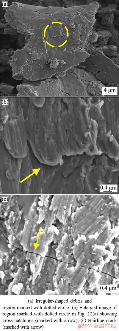
Fig. 12 SEM images of 7.5 wt.% MoS2 hybrid composite wear debris at 150 °C
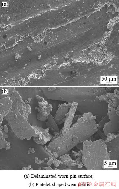
Fig. 13 SEM images of 2.5 wt.% MoS2 hybrid composite at 200 °C
The increase in temperature to 250 °C leads to the abrasion of the Gr-reinforced and MoS2 reinforced hybrid composite worn pin surfaces by the counterface asperities. The induction of abrasion also debonds the B4C particles from the matrix material. The debonded B4C particles and delaminated debris move freely and cause more abrasion on the contact surfaces. The combined abrasion induced by the counterface asperities, delaminated debris, and debonded B4C particles is so severe that a layer of material is removed from the worn pin surface (Fig. 14). The dotted lines trace the boundary of the region from where the layer of pin material of the 5 wt.% Gr hybrid composite is removed. Deep sliding grooves (marked with arrow) are observed on the abraded region.
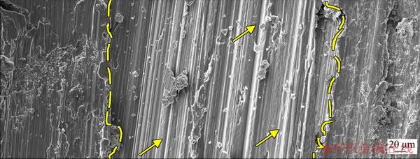
Fig. 14 SEM image showing abraded worn pin region (traced with dotted lines) and deep sliding grooves (marked with arrows) on worn pin surface of 5 wt.% Gr hybrid composite at 250 °C
The wear debris formed is long and ribbon- shaped (Figs. 15(a) and (b)). The production of this type of wear debris is linked to microcutting where the plastically rigid counterface asperities abrade the softer worn pin surface to produce ribbon- shaped wear debris. SEM images of ribbon-shaped wear debris of the 5 wt.% MoS2 hybrid composite and 5 wt.% Gr hybrid composite are shown in Figs. 15(a) and (b), respectively. Shallow cross- hatchings (marked with arrows) and peeled debris material in the form of a lathy strip (marked with open arrows) are observed on the wear debris of the 5 wt.% MoS2 hybrid composite (Fig. 15(a)). Overlapping longitudinal sliding grooves (marked with dotted arrows) are also present throughout the debris. These grooves are formed when the detached debris gets grooved longitudinally by the third-body particles and asperities of the counterface. Lamellar structure (marked with arrows) is observed on one side of the 5 wt.% Gr hybrid composite wear debris (Fig. 15(b)), while the other side has a smooth structure. The region marked with dotted circle in Fig. 15(b) is magnified and shown in Fig. 15(c); it shows continuous fringes which indicate the formation of shear bands [30]. Also, the counterface debris (Fig. 16) formed at 250 °C exhibits a lamellar structure. This phenomenon is suggestive of microcutting of the counterface by the debonded B4C particles. EDS was used to analyze the chemical composition of the counterface debris (30.13 O, 0.88 Mg, 10.29 Al, 0.02 Si, 0.31 Cr, and 58.37 Fe by wt.%). The primary constituent is seen to be Fe, and the presence of a substantial amount of O suggests the oxidation of the Fe debris.
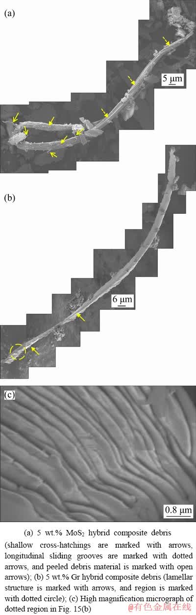
Fig. 15 SEM images showing ribbon-shaped wear debris at 250 °C
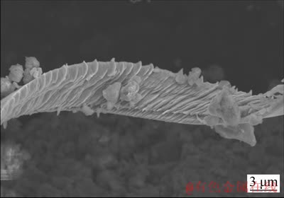
Fig. 16 SEM image of counterface debris at 250 °C
In the temperature range of 100 to 250 °C, the wear rate of the mono composite is higher than that of the Gr-reinforced and MoS2-reinforced hybrid composites (Figs. 2(a), (b), and (c)). This phenomenon is due to the absence of a solid lubricant phase in the mono composite. From 100 to 250 °C, the sheared solid lubricant particles of the disintegrated wear protective layer offer mitigated lubrication on the contact surfaces of the hybrid composites.
The sheared solid lubricant particles get abundant with increase in the addition of solid lubricant particles. So, the wear rate of the hybrid composites gradually decreases. Figure 17 illustrates this phenomenon at 250 °C. PRASAD and McCONNELL [31] observed the ability of the sheared Gr layer to adhere to the metal surface and provide solid lubrication.
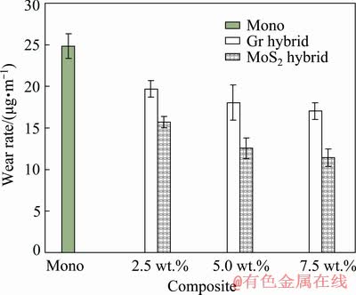
Fig. 17 Comparison plots of wear rates for mono composite, Gr-reinforced and MoS2-reinforced hybrid composites at 250 °C
3.2 Effect of temperature on friction coefficient
The variation of friction coefficient of different composites is plotted as a function of temperature as shown in Fig. 18. Figure 18(a) shows the friction coefficients of the mono composite, 2.5 wt.% Gr hybrid composite, and 2.5 wt.% MoS2 hybrid composite as a function of temperature. Figure 18(b) shows the friction coefficients of the mono composite, 5 wt.% Gr hybrid composite, and 5 wt.% MoS2 hybrid composite as a function of temperature. Figure 18(c) shows the friction coefficients of the mono composite, 7.5 wt.% Gr hybrid composite, and 7.5 wt.% MoS2 hybrid composite as a function of temperature. In the case of the mono composite, the friction coefficient decreases with increase in temperature up to 100 °C due to the lubrication offered by the wear protective layer. The combined lubrication provided by wear protective layer and its solid lubricant phase reduces the friction coefficient of the Gr-reinforced and MoS2- reinforced hybrid composites up to 100 °C. Also, the friction coefficient of the hybrid composites reduces with the increase in the addition of solid lubricant particles. Figure 19(a) shows this phenomenon at 100 °C.
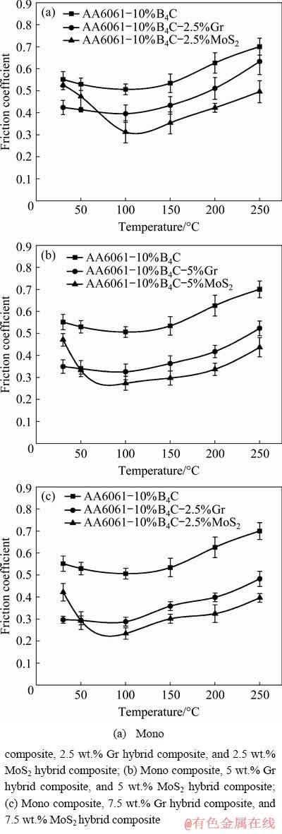
Fig. 18 Variation of friction coefficients for different composites as function of temperature
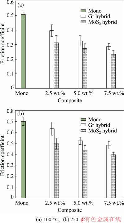
Fig. 19 Comparison plots of friction coefficients for mono composite and Gr-reinforced and MoS2-reinforced hybrid composites at different temperatures
The wear protective layer of the hybrid composites cracks at 150 °C, leading to its disintegration. The onset of severe adhesion causes an increase in the friction coefficient of the hybrid composites, and as the temperature increases to 200 °C, delamination is induced. As the temperature further increases to 250 °C, the delaminated debris, the debonded B4C particles, and the counterface asperities impart abrasion, leading to the increase in friction coefficient of the Gr-reinforced and MoS2- reinforced hybrid composites. Meanwhile, the sheared solid lubricant particles reduce the friction coefficient, as they get abundant with the increase in the addition of solid lubricant particles. Figure 19(b) shows this phenomenon at 250 °C.
3.3 Effect of temperature on lubrication provided by Gr-reinforced and MoS2- reinforced hybrid composites
It is noted that the lubrication is not an intrinsic property of Gr [32]. Lubrication characteristic of Gr depends on the presence of environmental contaminants, such as water or hydrocarbons, between the layers. Above the room temperature, the environmental contaminants desorb, leading to the degradation of the lubricating characteristics of Gr [33]. Unlike Gr particles, the MoS2 particles are an intrinsic solid lubricant [34], and the presence of environmental contaminants is detrimental to its lubricating effectiveness [33,35]. Therefore, the MoS2-reinforced hybrid composites exhibit poor tribological properties compared to the Gr-reinforced ones at the initial test temperature (Figs. 2 and 18). However, as the temperature increases, the contaminants desorb, and the MoS2 particles exhibit better lubrication characteristics [36]. Hence, the MoS2-reinforced hybrid composites exhibit better tribological properties than the Gr-reinforced ones at higher temperatures, i.e., from 100 to 250 °C (Figs. 2 and 18).
3.4 HRTEM and EBSD images of worn pin surfaces
During sliding at 150 °C, severe plastic deformation is induced on the worn pin surfaces of the Gr-reinforced and MoS2-reinforced hybrid composites, leading to the formation of deformation bands [37]. Figures 20(a) and (b) show TEM images of the deformation bands (traced with dotted line) formed on the worn pin surfaces of the 7.5 wt.% Gr hybrid composite and 7.5 wt.% MoS2 hybrid composite, respectively, tested at 150 °C.
Also, high dislocation density (marked with arrow) is observed on the worn pin surfaces of these hybrid composites. The sliding wear studies on Mg-Al-Zn alloy below 400 °C revealed the formation of parallel deformation bands [38]. The formation of deformation bands becomes prominent with the dynamic recovery, and also, subgrains are formed at 150 °C due to dynamic recovery. Figure 21 shows EBSD map of the subgrains of the matrix material formed on the worn pin surface of the 7.5 wt.% MoS2 hybrid composite.
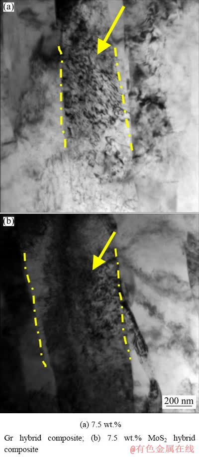
Fig. 20 TEM images showing deformation bands (traced with dotted lines) and high dislocation density (marked with arrow) on worn pin surfaces at 150 °C
The SAD patterns of the 7.5 wt.% MoS2 hybrid composites tested at 150 and 200 °C are shown in the upper left insets of Figs. 22(a) and (b), respectively. The SAD patterns consist of spotty rings. The spotty rings indicate fine crystalline structure of the worn pin surface, which is formed due to dynamic recrystallization. Using SAD patterns, DAUTZENBERG [39] observed the dynamic recrystallization of the Cu pin worn under dry sliding conditions against EN 43B steel ring. Figures 23(a) and (b) show the corresponding dark field TEM images of Figs. 22(a) and (b), which reveal some of the dynamically recrystallized grains (white grains).
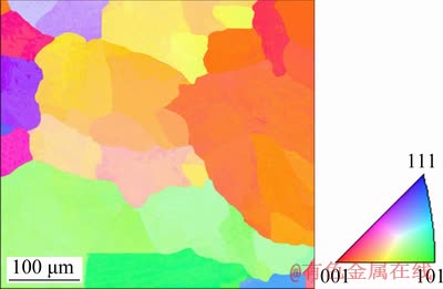
Fig. 21 EBSD map showing formation of subgrains on worn pin surface of 7.5 wt.% MoS2 hybrid composite at 150 °C
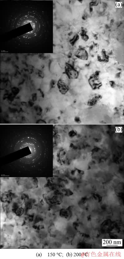
Fig. 22 Bright field TEM images of worn pin surfaces of 7.5 wt. % MoS2 hybrid composite showing fine crystalline structure at different temperatures
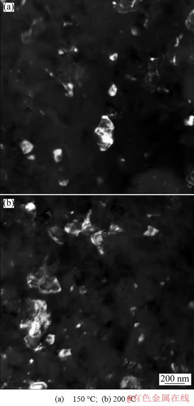
Fig. 23 Dark field TEM images of worn pin surfaces of 7.5 wt.% MoS2 hybrid composite showing dynamically recrystallized grains (white grains)
4 Conclusions
(1) For the entire range of temperature studied (30 to 250 °C), the tribological properties of the Gr- reinforced and MoS2-reinforced hybrid composites are better than those of the mono composite due to the presence of solid lubricant particles on the contact surfaces. The MoS2-reinforced hybrid composites exhibit better tribological properties than the Gr-reinforced ones in the temperature range of 100 to 250 °C, due to the improved lubricity of smeared MoS2 particles with the increase in temperature. Up to 100 °C, the wear rate and friction coefficient of the Gr-reinforced and MoS2-reinforced hybrid composites decrease due to the combined lubrication provided by the wear protective layer and its solid lubrication phase.
(2) At 150 °C, the wear rate of the hybrid composites is controlled by the plastic flow of the matrix material, which leads to the transfer of bulk worn pin material to the counterface, indicating that the wear mechanism induced is severe adhesion. Furthermore, at 150 °C, the microstructure of the 7.5 wt.% MoS2 hybrid composite reveals the formation of subgrains due to dynamic recovery. For 200 and 250 °C, the wear rate of the hybrid composites increases due to the induction of delamination and abrasion wear mechanisms, respectively.
(3) The friction coefficient of the hybrid composites increases with an increase in temperature from 100 to 250 °C. At 250 °C, abrasion causes an increase in the friction coefficient. The wear debris of the tribo-couple produced at this temperature has the lamellar structure, indicating highly abrasive conditions.
Acknowledgements
The corresponding author thanks National Institute of Technology Calicut, India, for the financial support provided to carry out this research work.
References
[1] MIRACLE D B. Metal matrix composites―From science to technological significance [J]. Composites Science and Technology, 2005, 65: 2526-2540.
[2] GECU R, KARAASLAN A. Volume fraction dependent wear behavior of titanium-reinforced aluminum matrix composites manufactured by melt infiltration casting [J]. Journal of Tribology, 2018, 141: 021603.
[3] ROHATGI P K. Metal matrix composites [J]. Defence Science Journal, 1993, 43: 323-349.
[4] PRASAD S V, ROHATGI P K. Tribological properties of Al alloy particle composites [J]. JOM, 1987, 39: 22-26.
[5] GECU R, ATAPEKM S H, KARAASLAN A. Influence of preform preheating on dry sliding wear behavior of 304 stainless steel reinforced A356 aluminum matrix composite produced by melt infiltration casting [J]. Tribology International, 2017, 115: 608-618.
[6] FAN Cai-he, LING Ou, HU Ze-yi, YANG Jian-jun, GANG Chen, YAN Hong-ge. Microstructures and mechanical properties of BP/7A04 Al matrix composites [J]. Transactions of Nonferrous Metals Society of China, 2019, 29: 2027-2034.
[7] SHARMA A, SHARMA V M, PAUL J. A comparative study on microstructural evolution and surface properties of graphene/CNT reinforced Al6061-SiC hybrid surface composite fabricated via friction stir processing [J]. Transactions of Nonferrous Metals Society of China, 2019, 29: 2005-2026.
[8] ABBASIPOUR B, NIROUMAND B, VAGHEFI S M, ABEDI M. Tribological behavior of A356-CNT nanocomposites fabricated by various casting techniques [J]. Transactions of Nonferrous Metals Society of China, 2019, 29: 1993-2004.
[9] KENNEDY A. The microstructure and mechanical properties of Al-Si-B4C metal matrix composites [J]. Journal of Materials Science, 2002, 37: 317-323.
[10] MONIKANDAN V V, JOSEPH M A, RAJENDRAKUMAR P K, SREEJITH M. Tribological behavior of liquid metallurgy-processed AA6061-B4C composites [J]. Materials Research Express, 2015, 2: 1-11.
[11] MONIKANDAN V V, JOSEPH M A, RAJENDRAKUMAR P K. Dry sliding tribological studies of AA6061-B4C-Gr hybrid composites [J]. Journal of Materials Engineering and Performance, 2016, 25: 4219-4229.
[12] MONIKANDAN V V, JOSEPH M A, RAJENDRAKUMAR P K. Dry sliding wear studies of aluminum matrix hybrid composites [J]. Resource-efficient Technologies, 2016, 2(S): s12-s24.
[13] JIANG J, STOTT F H, STACK M M. The role of tribo-particulates in dry sliding wear [J]. Tribology International, 1998, 31: 245-256.
[14] SCIULLI E B, ROBINSON G M. A study of the effect of wear particles and adhesive wear at high contact pressures [J]. ASLE Transactions, 1958, 1: 312-318.
[15] LIU YAO-hui, DU Jun, YU SI-rong, WANG WEI. High temperature friction and wear behavior of Al2O3 and/or carbon short fibre reinforced Al-12Si alloy composites [J]. Wear, 2004, 256: 275-285.
[16] RAJARAM G, KUMARAN S, RAO T S, KAMARAJ M. Studies on high temperature wear and its mechanism of Al-Si/graphite composite under dry sliding conditions [J]. Tribology International, 2010, 43: 2152-2158.
[17] XIONG D S. Lubrication behavior of Ni-Cr-based alloys containing MoS2 at high temperature [J]. Wear, 2001, 251: 1094-1099.
[18] ZHAN Y, ZHANG G. The role of graphite particles in the high-temperature wear of copper hybrid composites against steel [J]. Materials & Design, 2006, 27: 79-84.
[19] RYNIO C, HATTENDORF H, KLOWER J, EGGELER G. The evolution of tribolayers during high temperature sliding wear [J]. Wear, 2014, 315: 1-10.
[20] MONIKANDAN V V, JACOB J C, JOSEPH M A, RAJENDRAKUMAR P K. Statistical analysis of tribological properties of aluminum matrix composites using full factorial design [J]. Transactions of the Indian Institute of Metals, 2015, 68: 53-57.
[21] HARISH S, BENSELY A, LAL D M, RAJADURAI A, LENKEY G B. Microstructural study of cryogenically treated EN 31 bearing steel [J]. Journal of Materials Processing Technology, 2009, 209: 3351-3357.
[22] KAMEI K, WILLIAM A, KOVEILE L, AHMAD N, CHAKRAVORTY A, DAVIS R. An experimental study of the effect of thermal treatments & charpy impact test parameters on impact toughness of EN 31 steel [J]. Journal of Mechanical and Civil Engineering, 2014, 11: 17-22.
[23] LIU Y B, LIM S C, RAY S, ROHATGI P K. Friction and wear of aluminium-graphite composites: The smearing process of graphite during sliding [J]. Wear, 1992, 159: 201-205.
[24] SANNINO A P, RACK H J. Surface topography evolution during sliding wear of 2009 Al-SiCp/17-4 PH [J]. Wear, 1995, 181-183: 202-211.
[25] PAUSCHITZ A, ROY M, FRANEK F. Mechanisms of sliding wear of metals and alloys at elevated temperatures [J]. Tribology International, 2008, 41: 584-602.
[26] ZHOU Y H, HARMELIN M, BIGOT J. Sintering behavior of ultra-fine Fe, Ni and Fe-25wt.%Ni powders [J]. Scripta Metallurgica, 1989, 23: 1391-1396.
[27] STOTT F H, JORDAN M P. The effects of load and substrate hardness on the development and maintenance of wear- protective layers during sliding at elevated temperatures [J]. Wear, 2001, 250: 391-400.
[28] BLAU P J. Elevated-temperature tribology of metallic materials [J]. Tribology International, 2010, 43: 1203-1208.
[29] SUH N P. The delamination theory of wear [J]. Wear, 1973, 25: 111-124.
[30] CAMPBELL C E, BENDERSKY L A, BOETTINGER W J, IVESTER R. Microstructural characterization of Al-7075-T651 chips and work pieces produced by high-speed machining [J]. Materials Science and Engineering A, 2006, 430: 15-26.
[31] PRASAD S V, McCONNELL B D. Tribology of aluminum metal-matrix composites: Lubrication by graphite [J]. Wear, 1991, 149: 241-253.
[32] SAVAGE R H. Graphite lubrication [J]. Journal of Applied Physics, 1948, 19: 1-10.
[33] BUCKLEY D H. Surface effects in adhesion, friction, wear, and lubrication [M]. Amsterdam: Elsevier, 1981.
[34] LANCASTER J K. A review of the influence of environmental humidity and water on friction, lubrication and wear [J]. Tribology International, 1990, 23: 371-389.
[35] PETERSON M B, JOHNSON R L. Friction and wear investigation of molybdenum disulfide. I: Effect of moisture [R]. Nasa Technical Reports Server, 1953: 1-28. https:// ntrs.nasa.gov/archive/nasa/casi.ntrs.nasa.gov/19930083561.
[36] PETERSON M B, JOHNSON R L. Friction and wear investigation of molybdenum disulfide. II: Effects of contaminants and method of application [R]. Nasa Technical Reports Server, 1954: 1-19. https://ntrs.nasa.gov/archive/ nasa/casi.ntrs.nasa.gov/19930083852.
[37] LEE C S, DUGGAN B J, SMALLMAN R E. A theory of deformation banding in cold rolling [J]. Acta Metallurgica et Materialia, 1993, 41: 2265-2270.
[38] DAS S, MORALES A T, ALPAS A T. Microstructural evolution during high temperature sliding wear of Mg- 3%Al-1%Zn (AZ31) alloy [J]. Wear, 2010, 268: 94-103.
[39] DAUTZENBERG J H. The role of dynamic recrystallization in dry sliding wear [J]. Wear, 1980, 60: 401-411.
V. V. MONIKANDAN 1, P. K. RAJENDRAKUMAR2, M. A. JOSEPH2
1. Department of Production Engineering, PSG College of Technology, Coimbatore 641004, Tamilnadu, India;
2. Department of Mechanical Engineering, National Institute of Technology, Calicut 673601, Kerala, India
摘 要:通过搅拌铸造法制备AA6061-10wt.%B4C单一复合材料,Gr(Gr为石墨)颗粒含量为 2.5、5、7.5 wt.%的AA6061-10wt.%B4C-Gr 混杂复合材料,和MoS2颗粒含量为2.5、5、7.5 wt.%的AA6061-10wt.%B4C-MoS2 混杂复合材料。采用销-盘式摩擦试验机(对磨材料为EN31)研究温度对复合材料干滑动摩擦行为的影响。在30~100 °C的温度范围内,由于摩擦保护层及其固体润滑相的共同润滑作用,Gr增强和MoS2增强的混杂复合材料的磨损率和摩擦因数均下降。对磨损表面进行扫描电镜观察,结果表明,150、200和 250 °C下的磨损机制分别为重度粘着磨损、剥层磨损和磨粒磨损。透射电镜结果显示,150 °C时,混杂复合材料中形成了变形带和精细的晶体结构,分别是由严重的塑性变形和动态再结晶造成的。
关键词:铝基混杂复合材料;高温摩擦学行为;固体润滑;变形带;动态再结晶
(Edited by Wei-ping CHEN)
Corresponding author: V. V. MONIKANDAN; Tel: +91-8943001755; Fax: +91-4952287250; E-mail: saai.manikandan@gmail.com
DOI: 10.1016/S1003-6326(20)65289-X

