
Numerical simulation for isothermal dendritic growth of succinonitrile-acetone alloy
CHEN Zhi(陈 志)1, CHEN Chang-le(陈长乐)1, HAO Li-mei(郝丽梅)2
1. School of Science, Shaanxi Key Laboratory of Condensed Matter Structures and Properties,
Northwestern Polytechnical University, Xi’an 710072, China;
2. Department of Basic Courses, Xi’an University of Science and Technology, Xi’an 710054, China
Received 11 June 2007; accepted 13 September 2007
Abstract: Numerical simulation based on phase field method was developed to describe the solidification of two-dimensional isothermal binary alloys. The evolution of the interface morphology was shown and the effects of phase field parameters were formulated for succinonitrile-acetone alloy. The results indicate that an anti-trapping current(ATC) can suppress many trapped molten packets, which is caused by the thickened interface. With increasing the anisotropy value from 0 to 0.05, a small circular seed grows to develope secondary dendritic, dendritic tip velocity increases monotonically, and the solute accumulation of solid/liquid interface is diminished distinctly. Furthermore, with the increase of the coupling parameter value, the interface becomes unstable and the side branches of crystals appear and grow gradually.
Key words: phase field method; succinonitrile-acetone alloy; dendritic growth; tip velocity; anti-trapping current; anisotropy
1 Introduction
Dendritic is a common pattern during melt solidification, which influences the microstructures and mechanical properties of materials obtained in casting. Therefore, the development of dendrite is a key problem in material science and condensed matter physics[1-3]. Transparent materials have been used to study dendritic growth condition because of the observability property. When crystal nucleus are under the state of undercooling, tip velocity and morphology can reflect dendritic growth, which makes phase field method possible to contrast and analyze with solvability theory. For the most simulation methods, a global model is required to describe the details of the microstructure evolution process, which renders the problem about solution of a complete time dependent Stefen problem[4]. It is extremely challenging to solve this problem by means of front tracking method owing to the large deformation of the dendritic shape[5], whereas phase field method circumvents the problem of front tracking [6], and phase field method based on diffused interface model is extensively applied in the microstructure simulation in the course of solidification.
With the development of phase field method, the simulation of dendritic growth has been greatly simplified. In the early application of phase field method, many problems occur. Furthermore, the prominent problem is that interface thickness must be much smaller than that of thermal boundary to meet sharp interface limit, which makes it difficult to simulate. The interface kinetics coefficient of Karma and Rappel model can be eliminated by choosing appropriate parameters. Interface thickness can be released to the order of microstructures, and phase field method makes great progress[7], on which most of the later models are improved[8-9]. However, the thin interface phase field model results in anomalous interface effects[10-11], such as chemical potential jump, surface stretching, and surface diffusion. It is mainly because the solute atoms cannot escape fast enough into the liquid in order to maintain local chemical equilibrium state. In 2001, KARMA[12] solved the problem by introducing anti-trapping current(ATC). This model is to import an artificial solute current into the diffusive interface so that the solute trapping effect resulting from the discontinuity of chemical potential jump can be compensated. In the meantime, this model gives sufficient freedom in selecting appropriated interpolation and weighting functions to eliminate the other effects.
In this work, numerical simulation of isothermal dendritic growth of the succinonitrile acetone (SCN- ACE) alloy based on Karma’s model without and with ATC was calculated, and the influence law of anisotropy value in a certain range and coupling parameter value to isothermal dendritic growth was discussed.
2 Phase field model
The Karma phase field model can be used to simulate dilute binary alloys[12]. It has been derived and extensively validated by RAMIREZ and BECKERMANN [9]. This model is reduced to the sharp interface model with a thin interface limit, where the width of the diffuse interface is larger than the real width of a solid/liquid interface, and kinetic effects are negligible. We assume that all material properties are constant, the solute diffusivity in the solid is neglected, and thermal diffusion coefficients of the solid and liquid are equal[13-14].
Let  represent the phase field parameter, where =1 in the bulk solid phase, =-1 in the bulk liquid phase. The phase field varies smoothly between these two bulk values within the diffuse interface region. The anisotropic and dimensionless forms of the phase field and solute isothermal equations with ATC are given, respectively, by[9]
 (1)
(1)

 (2)
(2)
where the right second term of Eqn.(2) is ATC, τ(θ)=τ0as(θ) is a relaxation time, W(θ)=W0as(θ) is an anisotropic interface width,  is solute diffusivity in the liquid phase,
  is a coupling parameter between phase field and solute field, n=?
 is the unit vector normal to the interface, as(n)=1+γcos(4φ) is a surface energy anisotropy function,
  is the angle of the direction normal to the interface and the horizontal axis, γ is anisotropy parameter, k is the molar partition coefficient, Bn is man-made noise item, and t is time. All parameters in Eqns.(1) and (2) are dimensionless.
The expression of anti-trapping current is given by
 (3)
(3)
where jat is only non-zero inside the diffusion interface region.
Using asymptotic expansion, the capillary length d0 and kinetic coefficient expressions β are related to the phase field parameters, that is
d0=a1W0/λ (4)
 (5)
(5)
where a1 and a2 are constants, which depend on the double-well potential and other function choice of phase field equations. For the present choices, they are the same as those in Refs.[6], a1=0.883 9 and a2=0.626 7.
The dimensionless solute concentration, super- saturation, scaled magnitude of liquidus slope and fixed undercooling are respectively given by
 (6)
(6)
 (7)
(7)
 (8)
(8)
 (9)
(9)
where c is a mixture concentration that varies within the diffuse interface, c0 is the initial alloy concentration far from the solidification front,  is the equilibrium liquid concentration at system temperature, and Ω=0.55 in this paper.
3 Numerical simulation
3.1 Initial conditions and boundary conditions
Initial crystal radius is assumed to be r, that is
 (10)
(10)
where x is (100) direction and y is (010) direction.
and U apply Zero-Neumann boundary conditions:
 ;
; 
In order to save simulation effort, the four-fold symmetry allows to take one quarter domain for calculation[15].
3.2 Simulation method
Eqns.(1) and (2) are solved by standard second order finite difference formulate, time stepping is used by explicit Euler scheme, and ? is used by a nine-point formula with the nearest and the next nearest neighbors, which reduces the grid anisotropy[6]. The grid area is 500×500. For convenience, the following parameters are chosen: time step ?t=0.008, space step ?x=0.4, τ0=1, W0=1, λ=6.383, k=0.1, D=4, c0=0.1, γ=0.007, d0=0.139, commonly, t=16 000 ?t.
4 Results and discussion
4.1 Dendritic growth shape of succinonitrile-acetone alloy
In this paper, succinonitrile-acetone was selected as model material for binary metal because of its low melt point and transparent characteristic in solid or liquid phase, which is an important similar metal material for researching solidification process[16-17]. Table 1 lists the physical properties of succinonitrile-acetone alloy. SCN-ACE dendritic growth morphology is calculated by Eqns.(1) and (2).
Table 1 Physical properties of succinonitrile-acetone alloy

Fig.1 shows the phase field morphology of SCN- ACE at 12 000 ?t. Fig.1(a) shows phase field morphology without ATC, from which we can see that a circular seed grows into seaweed dendritic. It is mainly because that the anisotropy value of SCN-ACE alloy is too small to favor the direction of coordinate axes and its velocity. In the meantime, many trapped melt packets exist in the dendritic. The reason is that the solute trapping is inevitable with the ratio of 7.194 between the interface thickness and capillary length. Fig.1(b) shows the phase field morphology with ATC. It can be seen that the dendritic morphology is similar to that shown in Fig.1(a) in general, but dendritic arms are shortened and refined, and the phenomenon of solute trapping current is entirely suppressed. It can be explained that ATC increases solute boundary layer of dendritic tip front, which induces solute gradient descending on dendritic tip, suppresses dendritic tip growth, and drives secondary dendritic refining.
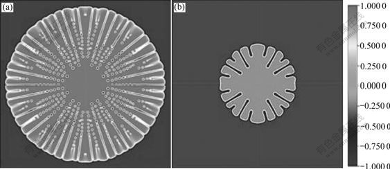
Fig.1 Phase field morphology of succinonitrile-acetone alloy dendritic at 12 000Δt: (a) Without anti-trapping current; (b) With anti-trapping current
Figs.2(a) and (b) show solute field morphology without and with ATC, respectively. It can be seen that the morphology is the same as phase field, which all can reflect characteristic of dendritic, so the remainder of the paper will be illustrated by phase field morphology with ATC.
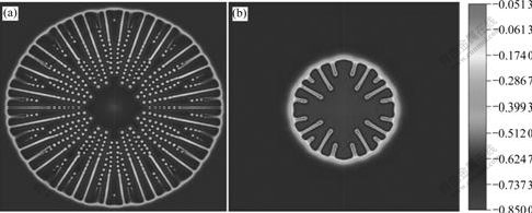
Fig.2 Solute field morphology of succinonitrile-acetone alloy dendritic at 12 000Δt: (a) Without anti-trapping current; (b) With anti-trapping current
4.2 Effect of anisotropy parameter
Usually, anisotropy is induced through angular dependence of the surface tension and the kinetic coefficient, which reflects the dependence of both the average bonding energy between atoms or molecules and the attacking kinetics on the local interface orientation [18], so the anisotropy controls the directions of dendritic growth. In fact, anisotropy should be the physical value of SCN-ACE. In this paper, we mainly investigate the anisotropy value from 0.00 to 0.05 by the well-known Wulff construction[19].
Fig.3 shows dendritic phase field morphology at various anisotropy values. It can be seen that when anisotropy value is 0, the crystal morphology is isotropy, and grows into seaweed crystal. With increasing the anisotropy value, the growth velocity of axes direction increases, side branches refine and shrink gradually, central axe branches grow larger, and corresponding secondary branches appear and grow.
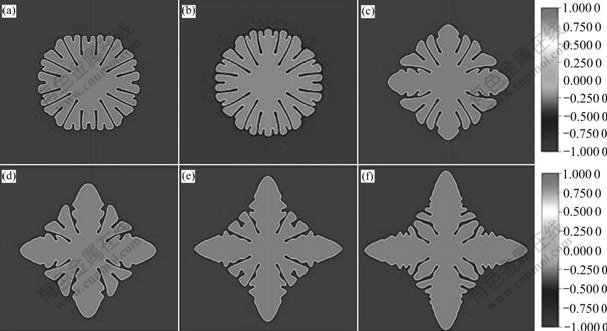
Fig.3 Phase field morphologies of dendritic at various anisotropy values: (a) γ=0; (b) γ=0.007; (c) γ=0.02; (d) γ=0.03; (e) γ=0.04; (f) γ=0.05
The calculated dendritic tip velocity at various anisotropy values is demonstrated in Fig.4. It can be found that dendritic tip velocity decreases to zero with increasing time when the anisotropy value is zero, which indicates that dendritic in the direction of central axes will no longer grow and begin to bifurcate. When anisotropy value is not zero, tip velocity is stable with the evolution of solidification. In addition. With increasing the anisotropy value, tip velocity increases monotonically. All phenomena stated above can be observed from Fig.3.
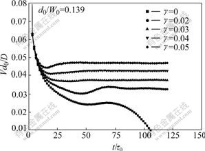
Fig.4 Calculated dendritic tip velocity at various anisotropy values
Fig.5 shows the plot of solidus concentration profiles in the solid along the central dendritic axis grid at various anisotropy values. It can be seen that all of the equilibrium solid solute ratios are equal at various anisotropy values, and the solute accumulation of solid/liquid interface distinctly descends with increasing the anisotropy value. It can be explained that faster tip velocity enhances solute transmittance and weakens the accumulation phenomena.
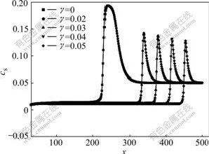
Fig.5 Plot of solidus concentration profiles in solid along central dendritic axis grid at various anisotropy values
4.3 Effect of coupling parameter
Fig.6 shows the dendritic morphologies at various coupling parameters. Phase field equation is associated with solute equation through coupling parameter, which can reflect the influence degree between them. It can be seen that circular seed only grows into a round crystal when λ is 1.595 8. With increasing coupling parameter, the influence of solute field boosts, interface stability becomes worse, and side branches appear and grow. We think that the bigger the coupling parameter is, the larger the phase field varies with solute field, which enhances the degree of anisotropy, renders much more disturbance at the interface and grows a non-circular crystal.
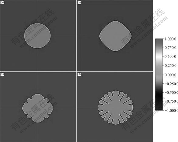
Fig.6 Dendritic morphologies at various coupling parameters: (a) λ=1.595 8; (b) λ=3.191 5; (c) λ=4.787 3; (d) λ=6.383 0
5 Conclusions
1) Isothermal dendritic growth without anti-trapping or with anti-trapping current was simulated based on phase field method. Solute trapping melt of SCN-ACE can be suppressed with anti-trapping current.
2) With increasing the anisotropy value from 0 to 0.05, the isothermal dendritic tip velocity increases monotonically and dendritic morphology develops from seaweed dendritic to secondary dendritic.
3) The crystal interface stability descends and side branches appear and grow with increasing coupling parameter values.
References
[1] LAN C W. Recent progress of crystal growth modeling and growth control [J]. Chemical Engineering Science, 2004, 59: 1437-1457.
[2] AL-RAWAHI N, TRYGGVASON G. Numerical simulation of dendritic solidification with convection: Two-dimensional geometry [J]. Journal of Computational Physics, 2002, 180: 471-496.
[3] MEDVEDEV D, KASSNER K. Lattice-Boltzmann scheme for dendritic growth in presence of convection [J]. Journal of Crystal Growth, 2005, 275: e1495-e1500.
[4] PLAPP M. Three-dimensional phase field simulations of directional solidification [J]. Journal of Crystal Growth, 2007, 303: 49-57.
[5] SHIH C J, LEE M H , LAN C W. A simple approach toward quantitative phase field simulation for dilute-alloy solidification [J]. Journal of Crystal Growth, 2005, 282: 515-524.
[6] KARMA A, RAPPEL W J. Phase-field method for computationally efficient modeling of solidification with arbitrary interface kinetics [J]. Physical Review E, 1996, 53(4): R3017-R3020.
[7] KARMA A, RAPPEL W J. Quantitative phase-field modeling of dendritic growth in two and three dimensions [J]. Physical Review E, 1998, 57(4): 4323-4349.
[8] KARMA A, RAPPEL W J. Phase-field model of dendritic sidebranching with thermal noise [J]. Physical Review E, 1999, 60(4): 3614-3625.
[9] RAMIREZ J C, BECKERMANN C. Examination of binary alloy free dendritic growth theories with a phase-field model [J]. Acta Materialia, 2005, 53: 1721-1736.
[10] KIMA S G, KIM W T, SUZUKI T. Phase-field model with a reduced interface diffuseness [J]. Journal of Crystal Growth, 2004, 263: 620-628.
[11] KIM S G, KIM W T. Phase field modeling of dendritic growth with high anisotropy [J]. Journal of Crystal Growth, 2005, 275: e355-e360.
[12] KARM A. Phase-field formulation for quantitative modeling of alloy solidification [J]. Physical Review L, 2001, 87(11): 115701-1-4.
[13] BRAGARD J, KARMA A, LEE Y G. Linking phase-field and atomistic simulations to model dendritic solidification in highly undercooled melts [J]. Interface Science, 2002, 10: 121-136.
[14] LAN C W, SHIH C J. Phase field simulation of non-isothermal free dendritic growth of a binary alloy in a forced flow [J]. Journal of Crystal Growth, 2004, 264: 472-482.
[15] XU Y, MCDONOUGH J M, TAGAVI K A. A numerical procedure for solving 2D phase-field model problems [J]. Journal of Computational Physics, 2006, 218: 770-793.
[16] BADILLO A, BECKERMANN C. Phase-field simulation of the columnar-to-equiaxed transition in alloy solidification [J]. Acta Materialia, 2006, 54: 2015-2026.
[17] JAMGOTCHIAN H, THI H N, BERGEON N, BILLIA B. Double-diffusive convective modes and induced microstructure localisation during solidification of binary alloys [J]. International Journal of Thermal Sciences, 2004, 43: 769-777.
[18] CINCA R G, PISCINA L R, CASADEMUNT J, MACHADO A H, KATONA T T, B?RZS?NYI T, BUKA A. Heat diffusion anisotropy in dendritic growth: Phase field simulations and experiments in liquid crystals [J]. Journal of Crystal Growth, 1998, 193: 712-719.
[19] VOORHEES P W, CORIELL S R, MCFADDEN G B. The effect of anisotropic crystal-melt surface tension on grain boundary groove morphology [J]. Journal of Crystal Growth, 1984, 67: 425-440.
Foundation item: Projects(50331040; 60171034) supported by the National Natural Science Foundation of China
Corresponding author: CHEN Zhi; Tel: +86-29-88493979; E-mail: c2002z@nwpu.edu.cn
(Edited by LI Xiang-qun)

