Role of misfit in precipitation crystallography in non-ferrous metals
��Դ�ڿ����й���ɫ����ѧ��(Ӣ�İ�)2007��������1��
�������ߣ����¸� ������ ���� Ҷ��
����ҳ�룺1 - 7
Key words��precipitation crystallography; interfacial orientation; Dg parallelism rules; misfit strain
Abstract: The crystallography and morphology of precipitates in different systems were rationalized based on the optimum matching conditions. The interfaces that obey these conditions were conveniently identified in reciprocal space, in terms of three Dg��s parallelism rules. The theoretic basis of the O-lattice and CSL/DSC theory for these rules was provided briefly. Examples of small lattice misfit system (a Ti alloy), and large lattice misfit systems (Al and Mg alloys) were presented. The effect of lattice parameters on the orientation relationship and morphology was also discussed.
������Ϣ��the National Natural Science Foundation of China

GU Xin-fu(���¸�), ZHANG Wen-zheng (������), ZHANG Min(����), YE Fei(Ҷ��)
Laboratory of Advanced Materials, Department of Materials Science and Engineering,
Tsinghua University, Beijing 100084, China
Received 15 July 2007; accepted 10 September 2007
Abstract: The crystallography and morphology of precipitates in different systems were rationalized based on the optimum matching conditions. The interfaces that obey these conditions were conveniently identified in reciprocal space, in terms of three Dg��s parallelism rules. The theoretic basis of the O-lattice and CSL/DSC theory for these rules was provided briefly. Examples of small lattice misfit system (a Ti alloy), and large lattice misfit systems (Al and Mg alloys) were presented. The effect of lattice parameters on the orientation relationship and morphology was also discussed.
Key words: precipitation crystallography; interfacial orientation; Dg parallelism rules; misfit strain
1 Introduction
Precipitation strengthening is a major mechanism for acquiring the desired mechanical property of many engineering nonferrous metals of technique importance. The crystallography and morphology of precipitates have been a major concern for microstructure control. Unfortunately, precipitation crystallography, as an essential aspect of the knowledge for understanding the morphology, is much less mature compared with the thermodynamics and kinetics of precipitation.
The morphology of precipitates is developed through the process of nucleation and growth of the precipitates. Since the interfacial energy is a major barrier to the nucleation, the precipitates with low energy interface are likely preferred in the nucleation process. Therefore, nuclei with the orientation relationship (OR) allowing low energy interface are likely favored. Usually, there exists an elastic strain field around each precipitate in the early stage of precipitation. The strain field and its interaction with the existing strain field due to defects or the other precipitates in the matrix may affect the assemblage of the precipitates. The shape of individual precipitates is affected by the elastic strain field, the interfacial energy, and the mobility of the interfaces. All these factors influencing the development of precipitate morphology are the function of the misfit distribution between the precipitate and matrix. Usually, the misfit is anisotropic. Though it is the source for the elastic strain field, the misfit strain can be fully relaxed by various interfacial structures. When the precipitates are closed by prominent facets, the long-range elastic strain is usually small. For this case, the shape and facets can be rationalized with geometric models in which long-range strain is neglected. The present analysis is also under this condition.
Different geometric approaches have been proposed to evaluate the misfit distribution and its role in the development of preferred interfaces and shapes of embedded phases. These include O-lattice model[1-2], structure ledge model[3], invariant line model[4-5], Burgers vector content method[6], O-line method[7-8], and near coincidence site (NCS) model[9]. Among these models, some can interpret both OR and interfacial orientation (IO), while others need input OR to calculate the IO. A common principle of these models is based on the hypothesis that nature favors reduction of misfit, but detailed criteria of misfit reduction vary from one model to another. A comparison between these models has been made in recent reviews[10-11]. Bollmann��s O-lattice theory has been considered as the most general tool for analyzing fit/misfit distribution in three dimensions (3D). ZHANG and WEATHERLY[10] recently summarized
optimum conditions of misfit configurations for preferred interfaces in general systems, and converted them to a set of simple rules in terms of measurable Dg by employing the tool of the O-lattice. Compared with the other approaches, which make analysis in direct space, the Dg approach is the most convenient method in analysis of the experimental data in the diffraction patterns and finding a clue for interpretation of the observations.
This paper first briefly reviewed the O-lattice theory and the Dg approach. The applications of these rules to precipitation crystallography in several nonferrous alloys were presented. A detailed analysis was given in particular to the example of S-phase in an Al alloy. Using these application examples, we demonstrated the important role of interfacial misfit in the development of the precipitation crystallography, and how the precipitation crystallography in completely different systems was rationalized by the simple Dg approach.
2 Backgrounds
2.1 Brief review of O-lattice/CSL/DSC
Consider the case in which the misfit between two lattices is small. The misfit field for this case is evaluated from a one-to-one correspondence, and it can be expressed by a misfit strain matrix, A, also called a transformation strain matrix. Two corresponding vectors xa and xb from different lattices, a and b, are related by xb =Axa. One can determine the principal O-lattice vector xO from[1]
TxO=bL (1)
where T=I-A-1 is the displacement matrix, I is the identity matrix, and bL is a Burgers vector of a lattice. A principal O-lattice vector points at a position of an O-lattice element where the misfit is zero. The solutions of xO corresponding to three non-coplanar bLs define a set of translation vectors for an O-point lattice. The periodic distribution of the point elements in the O-lattice defines the centers of good matching locations in 3D. The O-elements are separated from its neighbors by poor matching regions, called the O-cell walls. The O-cell wall traces in an interface are possible positions of misfit dislocations. The O-elements may also have a shape of line (O-line) and plane (O-plane) depending on the rank of T and bL. The principal O-lattice planes are the most important planes in the O-lattice structure. In the O-point lattice structure, a principal O-lattice plane contains periodic O-points, which are translated by two or three independent xO vectors. Therefore, this plane will contain two or three sets of periodic dislocations. In the O-line lattice structure, a principal O-lattice plane contains periodic O-lines, which will alternate with a set of misfit dislocations in an interface. In the O-plane lattice structure, the O-plane is a principal O-lattice plane, which is free of dislocations.
It is convenient to characterize the principal O-lattice plane with their reciprocal vectors. First, let us define a general displacement in reciprocal space[12]
DgI = ga-gb = T?ga (2)
where ga and gb are the reciprocal vectors of a and b lattice respectively. Any principal O-lattice plane is normal to one or more (parallel) DgI-p associated with the principal lattice plane ga-p, which is a low index plane containing two or three bL[12]. In an interface normal to DgI-p, the misfit can be fully accommodated by misfit dislocations with bL lying in the corresponding ga-p.
The O-lattice theory could also be applied to systems in which sizes of two lattices are remarkably different (also referred to large lattice misfit). In this case, the one-to-one correspondence is replaced by a properly constrained coincidence correspondence. The deviation of a pair of vectors in the real lattices from an ideal pair for the constrained coincidence site lattice (CCSL) is due to a secondary misfit strain(Constrained CSL and DSCL are adopted, because exact CSL/DSCL only realized in special lattice constants and OR in a hetero phase system, however it is rarely satisfied). The Burgers vectors of the secondary dislocations are among the constrained complete pattern shift lattice (CDSCL)[1]. On this basis, one can determine a secondary dislocation structure from a secondary O-lattice. A principal secondary O-lattice plane containing periodic or no secondary misfit dislocations is also defined by one or more (parallel) DgII-p vectors. When the secondary misfit is absent, i.e., when an ideal CSL exists, any plane in the CSL is still defined by Dg vectors[13]. In the next section we will show that it is convenient to describe ORs and preferred interfaces in terms of Dg.
2.2 Dg parallelism rules
The habit plane is a broad face or a major facet of a plate or lath shaped precipitate. Under an assumption that this preferred interface should correspond to a local minimum of interfacial energy, it may be regarded as a singular interface, as defined by SUTTON and BALLUFFI[14]. While interfacial energy of a general interface is difficult to measure and to calculate, ZHANG and WEATHERLY suggested to identify a singular interface according to its characteristic features in the interfacial structure, i.e. periodicity and singularity[10]. Periodicity implies that the low energy structure unit must repeat in the interface. Singularity is characterized by at least one of the following three optimum conditions: 1) elimination of interfacial steps; 2) free of dislocations in at least one direction; 3) one-to-one coincidence of steps and dislocations. Accordingly, twelve types of singular interfacial structures are identified for either small or large misfit systems[10]. These interfaces are either free of steps or containing steps that can cancel the interfacial misfit in one direction.
As explained in the previous section, the periodic condition can be fulfilled if the interface lies along a principal O-lattice plane, normal to at least one Dg. The singularity conditions can be identified by three Dg parallelism rules[10], describing a set of relationships of one Dg with other reciprocal vectors, g or Dg: Rule I: parallelism of a Dg with a rational plane g, corresponding to the optimum condition (1); Rule II: parallelism of two DgI-p��s, corresponding to the optimum condition (2) for small lattice misfit system; Rule III: parallelism of two Dg��s, which is applied to large lattice misfit systems, corresponding to the optimum condition ((2) and (3)). The normal of the singular interface is given by the parallel reciprocal vectors. While the interface orientation is fixed by the Dg vector(s), a Dg parallelism rule confines only two of the three degrees of freedom in the OR. Therefore, one additional constraint must be applied to fix the OR. Possible constraints have been discussed previously[10]: parallelism of two low indexed directions from two phases, as frequently occurs in different systems[15]; maximization of the dislocation spacing in the interfaces, as has been tested in different systems[7, 16]. When the lattice parameters are specially related, two Dg parallelism rules can be realized simultaneously. In such a case, the OR is fixed by two Dg parallelism rules. Numerous examples of systems obeying one or more rules have been listed previously [10].
Application of the Dg parallelism rules is experimentally convenience. The interface orientation can be recorded directly with Dg vectors, which are readily measured in electron diffraction patterns using TEM. In addition, the correspondence of an interface with a Dg vector can also be identified from Moir�� fringes visible in TEM images, because each Dg represents a set of Moir�� fringes visible in proper diffraction conditions. The plane matching property of Moir�� planes can also be used to test the interface structure. Moreover, the relationship between Dg and principal O-lattice plane can be used to test the Burgers vector(s) of the dislocations in the interface.
When the habit plane of a precipitate is parallel to low index planes in the adjacent phases, the habit plane must obey Rule I. Because the interface is normal to ga and gb, it must be also normal to Dg (=ga-gb). The rational interface often appears easy to understand. A typical example is the {100} habit plane of q? precipitate in Al-Cu alloys. However, it is less known that this coherent interface also obeys Rule III. Satisfaction of two rules (two optimum conditions) makes it special. The examples given in the next section place strong emphasis on the applications of the Rule II and Rule III, to illustrate how these rules are used to interpret the experimental observations of irrational interfaces.
3 Applications
3.1 Application of Rule II: example of a precipitates in Ti-7.26 % Cr alloy
The a precipitates in Ti alloys play an important role in the strengthening of the alloys. A systematic experimental study has been carried out recently in the precipitation crystallography and interfacial structure between a and b in Ti-Cr alloy[16]. The careful study revealed that the reproducible OR is irrational, without any rational planes or rational directions being parallel. The habit plane normal is defined by an irrational orientation of (-13 10.2 10.1)b (~//(-3.6 4.6 -1 -0.1)a). The reason for the irrationality becomes clear when the habit plane is identified with Dg. The habit plane was observed to obey Rule II, and it is normal to Dg(011)b = g(0 1 -1 0)a-g(0 1 1)b and Dg(-1 1 2)b = g(-1 2 -1 1)a-g(-1 1 2)b. The parallelism of these two Dg��s requires a special OR. As the associated property of Rule II, the habit plane must contain periodic O-lines[7, 10]. This was confirmed by the observation that the habit plane mainly contains a set of periodic dislocations lying in the direction of [5 2.6 2.8]b (~//[3.2 -4.2 0.1]a), with spacing of 11 nm. The Burgers vector of the dislocations determined from diffraction contrast analysis is [1 -1 1]b/2 ([2 -1 -1 3]a/6). This Burgers vector lies in plane (0 1 1)b and (-1 1 2)b associated with the parallel Dg, consistent with the properties of the principal O-lattice plane[10]. By inputting lattice parameters and the Burgers vector, in the condition of Rule II and maximum dislocation spacing, Ye et al.[16] have determined the OR required for Rule II, the habit plane, the direction and spacing dislocations in the habit plane based on the O-lattice theory and its extension[1, 12]. The calculated results are in good agreement with the experimental observations[16]. When the OR is fully constrained by the habit plane, the interfacial structure(s) in other facet(s) may not satisfy any optimum condition, but the facets have been developed[17]. The NCS model[9] and Moir�� plane property have been used to investigate the misfit distribution in 3D, and the orientation of another facet and the dislocation structure in this facet can be accounted for from this 3D misfit analysis[18].
3.2 Application of Rule I and III: �� precipitates in Mg
alloys
The Mg17Al12 (��) precipitates are the major strengthening phase in Mg-Al based alloys widely used in industry. The OR between �� (bcc) and �� phase (hcp matrix) is usually described by the Burgers OR(We use the variant of (0 1 1)�� // (0 0 0 1)�� and [1 -1 1]��//[2 -1 -1 0]�� here), and the precipitates have a lath shape with the habit plane parallel to (0 1 1)�� and (0 0 0 1)��[19]. This habit plane obeys Rule I, as it is normal to a g and a Dg. However, a careful examination of the high resolution TEM image of Mg17Al12 in an AZ91 alloy revealed inconsistence between Burgers OR and observation[20]. From the Moir�� patterns taken from the parallel zone axes of [0 1 1]�� and [0 0 0 1]��, one can notice that the pattern is not in accord with the symmetry of Dg vectors expected from the ideal Burgers OR. The observed pattern can be reproduced only if an deviation of ~0.5? between (1 -1 1)�� and (2 -1 -1 0)�� is introduced. This deviation can be interpreted by Rule III (since the misfit between two lattice is large), i.e. a rotation to ensure parallelism of Dg(0 -3 3)b = g(1 -1 0 0)a-g(0 -3 3)b and Dg(6 3 -3)b =g(0 2 -2 0)a- g(6 3 -3)b, as discussed in details by DULY et al[20]. The 0.5? deviation between (1 -1 1)�� and (2 -1 -1 0)�� has been confirmed by a recent TEM study[21]. While the deviation from the Burgers OR can be accounted for by Rule III, the interface normal to the parallel Dg��s only defines a major side facet rather than the habit plane of the precipitate plates. The resulting orientation of the major side facet is approximately (4 3 -3)��. The zone axis of these two prominent faceted interfaces enabled explanation of the long axis (or growth direction) [3 -2 2]�� of the precipitate laths[20]. As indicated in Section 2, a single Rule I for the habit plane only confines two degrees of freedom in the OR, the remaining one degree of freedom in this system is fixed by Rule III. Usually, the additional constraint to Rule I is parallelism of a pair of low index directions in the parallel planes, as in the ideal Burgers OR.
To further explain the preference of stepped facet (4 3 -3)�� to the terrace plane of (2 1 -1)��//(0 1 -1 0)��, ZHANG et al[22] recently calculated the interfacial structure in the facet normal to the parallel Dg��s, based on the CSL/DSCL model and O-lattice model[2]. They found that the proportion of good matching regions is higher and Burgers vector is smaller in the stepped interface than the one without steps. High misfit areas in the plane parallel to (2 1 -1)�� and (0 1 -1 0)�� are avoided by introducing the steps. The density of the steps is function of the secondary misfit in the terraces, since the secondary dislocations associated with the steps must cancel the misfit between near coincidence points defined by [1 -1 1]��/2 and [2 -1 -1 0]�� in the terraces. The major side facet can be regarded to contain a quasi invariant line because of the cancellation[23]. The rotation between (2 1 -1)�� and (0 1 -1 0)�� is a function of the step spacing and the difference of step heights defined in different lattices. As can be expected, when the misfit along [1 -1 1]�� and [2 -1 -1 0]�� is negligibly small, the steps become unnecessary, and the side facet should be parallel to (2 1 -1)�� // (0 1 -1 0)��.
It is interesting to note that the habit plane of Mg24Y5 precipitates in a Mg-Y alloy is parallel to (2 1 -1)�� and (0 1 -1 0)��, rather than (0 1 1)�� and (0 0 0 1)�� to become[24]. This habit plane obeys Rule I, corresponding to exact Burgers OR. Mg24Y5 phase have the same crystal structure as Mg17Al12, but its lattice parameter increases by about 6.8%. Due to this change, the misfit between [1 -1 1]��/2 and [2 -1 -1 0]�� in Mg-Y alloy is 1.3%( The misfit is defined as (|xp| - |xm|)/|xm|, where xp and xm are vectors of precipitate and matrix respectively), considerably smaller than the absolute value of (-4.3%) for the AZ91. However, this pair of vectors does not define a quasi invariant line. A reason for the steps being unfavorable is probably due to increase of misfit in the step height. The misfit of step heights in two phases is 4.1% for AZ91, but it is 10.3% for Mg-Y alloy. This interpretation is different from the model suggested by ZHANG and KELLY[25], who virtually applied Rule III to determine a deviation of 0.38? between [0 1 1]�� and [0 0 0 1]��, and a deviation by 1.82? of the habit plane from (2 1 -1)�� and (0 1 -1 0)��. It is difficult to detect the above deviations experimentally without special attention. To explain why habit plane (2 1 -1)��//(0 1 -1 0)�� becomes preferred to (0 1 1)�� and (0 0 0 1)��, we made a simple comparison on the secondary misfit strain in the directions normal to the good matching rows along [1 -1 1]�� and [2 -1 -1 0]�� in both interfaces. If we follow the construction of constrained CSL in ZHANG��s model for Mg17Al12[22], the spacing of three rows of atoms in �� along [2 -1 -1 0]�� should match with the one row spacing of atoms in �� along [1 -1 1]�� in both interfaces. At exact Burgers OR, the secondary row spacing misfit in plane (2 1 -1)��//(0 1 -1 0)�� is -4.0% for Mg17Al12 and is 1.9% for Mg24Y5; that in plane (0 1 1)��//(0 0 0 1)�� is 4.1% for Mg17Al12 and is 10.3% for Mg24Y5. The significant decrease of secondary misfit in (2 1 -1)��//(0 1 -1 0)��, and increase of the secondary misfit in (0 1 1)��//(0 0 0 1)�� due to the increase of lattice parameter of Mg24Y5 is possibly responsible for the change of the habit plane selection. A plate with the habit plane of (2 1 -1)��//(0 1 -1 0)�� is desirable for improving the strengthening effect, but high cost of Y source limits the application of this alloy.
3.3 Application of Rule I and III: S phase in Al-Cu-Mg alloy
The orthorhombic S phase (Al2CuMg) in Al-Cu-Mg based alloys has been considered as an important phase responsible to the high strength of the alloys. The precipitation crystallography of S phase has attracted attention of systematic TEM investigations. RADMILOVIC et al[26] reported two types of OR in the system, Both ORs share the common directions of [1 0 0]s//[1 0 0]a, which defines a direction of small misfit (0-0.5%). Type I OR is specified with (0 0 1)s//(0 2 1)a, and this is the habit plane of the precipitates. Type II OR is around 5? from the above OR, and the corresponding habit plane is (0 4 3)s//(0 2 1)a. WINKELMAN et al[27] found a range of ORs between the precipitates and the matrix. Two limits of the ORs have been specified as OR1, which is same as type I OR specified above, and OR2 specified by (0 -2 1)s//(0 1 4)a, [1 0 0]s//[1 0 0]a. The major facet of OR1 has been interpreted by RADMILOVIC et al[26] in terms of almost identical atomic arrangement in the (0 0 1)s and (0 2 1)a planes. The exact OR1 could be described by Rule I, since (0 0 1)s and (0 2 1)a are parallel, either g is parallel to their difference vector Dg.
We will demonstrate below an explanation of type II and OR2 with Rule III. Fig.1(a) is a simulation of superimposed diffraction patterns guided by type II OR in the insert in Fig.4(b) of Ref.[26]. The lattice parameters of bs=0.930 nm, cs=0.708 nm used in the simulation were adopted from Ref.[26]. The condition of Dg(0 2 0)a (=g(0 2 0)a-g(0 0 2)s) being parallel to Dg(0 2 -2)a (= g(0 2 -2)a-g(0 6 2)s) was used to calculate the OR. The resulted OR is 5.03? from OR1, consistent with the measured angle of 4.8? and the direction of the parallel Dg is 0.28? from the (0 4 3)s, the measured orientation of habit plane. Full agreement is obtained in the OR and the habit plane orientation between the calculated and experimental results.
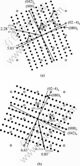
Fig.1 Simulated diffraction patterns for type II OR (a) and OR2 (b) at zone axis of [1 0 0]s//[1 0 0]a (Open circles stand for reciprocal lattice points in matrix, and filled ones are for S phase)
Fig.1(b) is a calculated superimposed diffraction patterns guided by OR2 in Ref.[27]. The lattice parameters of bs=0.925 nm, cs=0.709 nm used by the simulation were adopted from Ref.[27]. The condition of Dg(0 0 -2)a (=g(0 0 -2)a-g(0 4 -1)s) being parallel to Dg(0 2 0)a (= g(0 2 0)a-g(0 2 3)s) was used to calculated the OR. The resulted OR is 6.63? from OR1, and (0 -2 1)s deviates from (0 1 4)a by ~0.85?. The nominated OR2 defined by WINKELMAN et al, in condition of parallelism of (0 -4 2)s and (0 1 4)a, is 7.5? from OR1. The measured maximum rotation is (6.9��0.25)?, which experimentally identifies OR2. Comparing to this value, our calculated OR is closer to measured OR2 than the nominated OR2. However, the interface defined by parallel Dg is 6.7? from (0 1 4)a and 7.5? from (0 -4 2)s, showing relative large discrepancy from the observed habit plane corresponding to OR2 specified by WINKELMAN et al[27].
RADMILOVIC et al[26] have interpreted their observed Type II OR with an invariant line model. The quasi invariant line, determined from the present Dg parallelism rule, can be expressed as [0 1 -1.35]s and [0 1 2.23]a, or approximately [0 3 -4]s and [0 4 9]a. The interface containing this quasi invariant line is -50.7? from (0 2 1)a, closer to the measured value of -52? than -49?, calculated by RADMILOVIC et al[26]. KOVARIK et al[28] noticed a problem in the model by RADMILOVIC et al[26]. By using a structural ledge model, they explained the interface plane of (0 4 3)s//(0 4 9)a (which is equivalent to (0 9 -4)a in the present OR variant). Our calculated habit plane is very close to that given in their model. Our approach is more general in that the habit plane is not limited to rational planes.
Our approach in terms of the quasi invariant line is similar to the invariant line model by RADMILOVIC et al[26]. The disagreement in results is due to different selections of the lattice correspondence for calculation of the strain. In the plane normal to [1 0 0]s//[1 0 0]a, their selected corresponding pairs are [0 1 -2]a��[0 1 0]s and 1/2[0 7 3]a��[0 0 2]s[26]. Our correspondence for the secondary strain is [0 1 -2]a��[0 1 0]s and 1/2[0 3 1]a��[0 0 1]s. However, a quasi invariant line rather than a secondary invariant line is determined. The correspondence for the quasi invariant line is [0 0 -3]a��[0 1 0]s and [0 1 0] a��[0 0 1]s, as guided by the application of Dg parallelism rules[10]. To avoid mistake due to any objective bias, the calculated interfacial structure should be tested against the observation.
The structure of the interface corresponding to type II OR was simulated in Fig.2. The planes related by the parallel Dg��s are plotted to show full registry of these plane in the interface. If the coincidence points are arranged near the steps, the simulated interfacial structure in Fig.2 agrees almost exactly with the HRTEM image in Fig.4(c) of Ref.[26]. Unlike the previous application of Rule III [22, 23], in which severe misfit distortion is associated with steps, the steps are associated with good matching points in the interface of S phase.
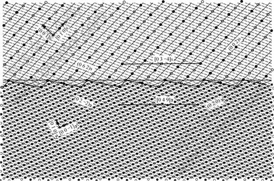
Fig.2 Atomic structure of interface that satisfies Rule III, viewed along [1 0 0]s//[1 0 0]a(The small open and closed circles represent lattice points in matrix, while the big ones are for S phase (points at [1/2 1/2 0]s are added for comparison with the observation in Ref.[26]). Open and closed circles indicate the lattice points in different layers along [1 0 0]s//[1 0 0]a)
The statistic study by WINKELMAN et al[27] has identified a correlation between the OR and the lattice parameter of the S phase. They showed an interesting observation of two ORs (or continuous change of OR between the two) of a single precipitate with respect to the matrix. While the part with a pair of long and flat interfaces parallel to (0 0 1)s and (0 2 1)a exhibits OR1, the part containing steps deviates from OR1 by 4.2?. As explained early, the mismatch between the spacing of the steps is responsible to the rotation. Each step has an edge component of displacement when the step heights in two phases are different, so a series of steps has an effect of an edge dislocation wall as in a small angle tilt grain boundary. When the spacing and heights of the steps differ at one location from another, as in Fig.1 in Ref.[27], one will expect that the rotation angle does not have a fixed value. The corresponding OR, the rotation from a reference OR, depends on the force balance of the step structure around an embedded precipitate. When the spacing and heights of the steps are mainly regular, the rotation can be determined from simple geometry. Rule III is applicable only if the steps spacing is such that a quasi invariant line can be defined. In this case, the OR is reproducible, but, as a function of the secondary misfit, it must vary with the lattice parameters. Another reason for variable OR is that step spacing may be larger than that required by the cancellation condition, since the equilibrium spacing may not be reached during the interface migration process. This explains why OR2 is the up limit of the variable ORs, because it likely corresponds to minimum step spacing.
4 Summary
The crystallography and morphology of precipitates in many alloys are governed by development of an optimum misfit distribution in the habit plane, or major facets. The crystallography is conveniently analyzed in reciprocal space, in terms of three Dg��s parallelism rules. The relationship of these rules with optimum interfacial structure is provided on basis of the O-lattice and CSL/DSC theory. Examples in Ti, Mg, and Al alloys are presented to show the applications of these rules to systems of either small or large lattice misfit, especially to illustrate how Rule II and III are used to interpret irrational OR and faceted interfaces. The common principle is that a preferred irrational interface should contain an invariant line or a quasi invariant line so that one-to-one matching (primary) or coincidence matching (secondary) is improved. Rule II is applied when the misfit is primary, e.g. Ti-Cr alloy, while Rule III is applied when the misfit is secondary, e.g. Mg and Al alloys used in the examples. Steps are often not favored in many systems, and then the habit plane should obey Rule I. The selection of rule(s) and proper lattice correspondence for misfit calculation vary with systems, depending on specific lattice parameters.
References
BOLLMANN W. Crystal defects and crystalline interfaces[M]. Berlin: Springer, 1970.
BOLLMANN W. Crystal lattices, interfaces, matrices[M]. Geneva: Bollmann, 1982.
RIGSBEE J M, AARONSON H I. A computer modeling study of partially coherent FCC:BCC boundaries[J]. Acta Metall, 1979, 27(3): 351-363.
DAHMEN U. Orientation relationships in precipitation systems[J]. Acta Metall, 1982, 30(1): 63-73.
LUO C P, WEATHERLY G C. The invariant line and precipitation in a Ni-45 wt.% Cr alloy[J]. Acta Metall, 1987, 35(8): 1963-1972.
KNOWLES K M, SMITH D A. The application of surface dislocation theory to the FCC-BCC interface[J]. Acta Cryst A, 1982, A38: 34-40.
ZHANG W Z, PURDY G R. O-lattice analyses of interfacial misfit. II. Systems containing invariant lines[J]. Philos Mag A, 1993, 68(2): 291-303.
QIU D, ZHANG W Z. A systematic study of irrational precipitation crystallography in fcc-bcc systems with an analytical O-line method[J]. Philos Mag, 2003, 83(27): 3093-3116.
LIANG Q, REYNOLDS W T J R. Determining interphase boundary orientations from near-coincidence sites[J]. Metall Mater Trans A, 1998, 29A(8): 2059-2072.
ZHANG W Z, WEATHERLY G C. On the crystallography of precipitation[J]. Prog Mater Sci, 2005, 50(2): 181-292.
QIU D, ZHANG W Z. Research progress in precipitation crystallography models[J]. Acta Mater Sinica, 2006, 42(4): 341-349. (in Chinese)
ZHANG W Z, PURDY G R. O-lattice analyses of interfacial misfit. I. General considerations[J]. Philos Mag A, 1993, 68(2): 279-290.
ZHANG W Z. Application of the DSCL in reciprocal space for the study of coincidence boundaries[J]. Scripta Mater, 1997, 37(2): 187-192.
SUTTON A P, BALLUFFI R W. Interfaces in crystalline materials[M]. Oxford: Oxford University Press, 1995.
KELLY P M, ZHANG M X. Edge-to-edge Matching-a new approach to the morphology and crystallography of precipitates[J]. Material Forum, 1999, 23: 41-62.
YE F, ZHANG W Z, QIU D. A TEM study of the habit plane structure of intragranular proeutectoid �� precipitates in a Ti-7.26 wt% Cr alloy[J]. Acta Mater, 2004, 52(8): 2449-2460.
YE F, ZHANG W Z. Dislocation structure of non-habit plane of a precipitates in a Ti-7.26 wt% Cr alloy[J]. Acta Mater, 2006, 54(4): 871-879.
YE F, ZHANG W Z, QIU D. Near-coincidence-sites modeling of the edge facet dislocation structures of [alpha] precipitates in a Ti-7.26 wt% Cr alloy[J]. Acta Mater, 2006, 54(20): 5377-5384.
CELOTTO S. TEM study of continuous precipitation in Mg-9wt%Al-1wt%Zn alloy[J]. Acta Mater, 2000, 48(8): 1775-1787.
DULY D, ZHANG W Z, AUDIER M. High-resolution electron microscopy observations of the interface structure of continuous precipitates in a Mg-Al alloy and interpretation with the O-lattice theory[J]. Philos Mag A, 1995, 71(1): 187-204.
XIAO X L, LUO C P, NIE J F, MUDDLE B C. Morphology and crystallography of ��-(Mg17Al12) precipitate in an AZ91 magnesium- aluminum alloy[J]. Acta Mater Sinica, 2001, 37(1): 1-7.
ZHANG M, ZHANG W Z, YE F. Interpretation of precipitation crystallography of Mg17Al12 in a Mg-Al alloy in terms of singular interfacial structure[J]. Metall Mater Trans A, 2005, 36(7): 1681-1688.
YE F, ZHANG W Z. Coincidence structures of interfacial steps and secondary misfit dislocations in the habit plane between Widmanstatten cementite and austenite[J]. Acta Mater, 2002, 50(11): 2761-2777.
ZHANG M X, KELLY P M. Morphology and crystallography of Mg24Y5 precipitate in Mg-Y alloy[J]. Scripta Mater, 2003, 48(4): 379-384.
ZHANG M X, KELLY P M. Edge-to-edge matching and its applications Part II. Application to Mg-Al, Mg-Y and Mg-Mn alloys[J]. Acta Mater, 2005, 53(4): 1085-1096.
RADMILOVIC V, KILAAS R, DAHMEN U, SHIFLET G J. Structure and morphology of S-phase precipitates in aluminum[J]. Acta Mater, 1999, 47(15): 3987-3997.
WINKELMAN G B, RAVIPRASAD K, MUDDLE B C. Orientation relationships and lattice matching for the S phase in Al�CCu�CMg alloys[J]. Acta Mater, 2007, 55(9): 3213-3228.
KOVARIK L, MILLER M K, COURT S A, MILLS M J. Origin of the modified orientation relationship for S(S'')-phase in Al-Mg-Cu alloys[J]. Acta Mater, 2006, 54(7): 1731-1740.
Foundation item: Projects(59871021, 50271035, 50471012) supported by the National Natural Science Foundation of China.
Corresponding author: ZHANG Wen-zheng; Tel: +86-10-62773795; Fax: +86-10-62771160; E-mail: zhangwz@tsinghua.edu.cn
(Edited by ZHAO Jun)

