文章编号:1004-0609(2015)-07-1798-10
基于质点逆向追踪的铝合金空心型材横断面温度的不均匀性
侯文荣1,张志豪1,谢建新1,马青梅2,盖洪涛2
(1. 北京科技大学 新材料技术研究院 材料先进制备技术教育部重点实验室,北京 100083;
2. 辽宁忠旺集团有限公司,辽阳 111000)
摘 要:采用挤压金属质点逆向追踪方法,分析了铝合金空心型材挤压过程中型材横断面温度分布不均匀性的原因及主要影响因素。结果表明:挤压过程中质点在分流孔内流动时的温度变化对模孔出口处型材横断面温度分布不均匀性的影响较大,而在焊合室内和模孔内流动时,温度变化对模孔出口处型材横断面温度分布不均匀性影响较小;挤压过程中各项热流作用对型材横断面温度分布不均匀性的影响程度由大到小依次为摩擦热、塑性变形热以及金属与工模具间的传热;通过模具结构设计和挤压工艺参数合理化,可使空心型材横断面温度分布的不均匀性得到较大的改善。
关键词:铝合金;空心型材;分流模挤压;金属流动;横断面温度;不均匀性
中图分类号: TG379 文献标志码:A
Temperature inhomogeneity on cross section of Al alloy hollow profile based on reverse point tracking method
HOU Wen-rong1, ZHANG Zhi-hao1, XIE Jian-xin1, MA Qing-mei2, GAI Hong-tao2
(1. Key Laboratory for Advanced Materials Processing, Ministry of Education,
Institute of Advanced Materials and Technology, University of Science and Technology Beijing, Beijing 100083, China;
2. Liaoning Zhongwang Group Co., Ltd., Liaoyang 111000, China)
Abstract: The reverse point tracking method was used to study the reason and influence factors of the temperature inhomogeneity on the cross section of Al alloy hollow profile. The results show that the temperature change in dividing process has a great effect on the temperature inhomogeneity on the cross section of the profile, while the effects of temperature change on the temperature inhomogeneity on the cross section of the profile in welding chamber and die hole are smaller. The influence extent of heat transfer during the extrusion on the temperature inhomogeneity on the cross section of the profile from large to small is friction heat deformation heat, and the heat transfer between the metal and die. By using the die structure design and the rationalization of extrusion parameters, the temperature inhomogeneity on the cross section of hollow profile is greatly improved.
Key words: Al alloy; hollow profile; porthole die extrusion; metal flow; cross section temperature; inhomogeneity
在挤压成形过程中,由于塑性变形热、摩擦热、金属与工模具之间的传热以及金属内部热传导等原因,导致挤压产品沿长度方向和横断面上均存在温度分布不均匀现象,从而影响挤压产品组织性能的均匀性[1-3]。控制温度分布均匀性是高性能铝合金型材挤压生产的关键技术之一[4]。
目前,解决挤压产品沿长度方向温度不均匀问题最有效的方法是实行等温挤压,有关等温挤压原理、技术、装备等方面的研究已取得诸多进展[5-8]。例如,李落星等[5]采用有限元模拟与PID控制原理相结合的速度控制等温挤压技术,使型材挤压的生产效率提高了20%~25%,同时型材的翘曲程度、尺寸稳定性也明显改善。然而,关于挤压产品横断面温度不均匀性问题却尚未引起挤压科研工作者和生产者的足够重视,缺乏有关基础理论和控制方法的研究。
对于图1所示的扁宽空心型材,本文作者[9]的前期研究结果表明,模孔出口处型材横断面上的最高温度与最低温度的差值(以下简称横断面最大温差)高达数十摄氏度(℃)。轨道交通和航空等领域的大型扁宽铝合金型材,其宽度可达600~700 mm以上,横断面上的温度不均匀分布现象将更为显著。横断面温度的不均匀分布不但直接影响挤压型材的形状和尺寸精度、组织性能均匀性以及残余应力分布,而且还会增大挤压过程温度控制的难度,导致挤压工艺参数的可调控范围变窄。在实际挤压生产中,当挤压产品的横断面温差较大时,若采用横断面上某一点的测温结果作为挤压过程的温度控制依据,容易导致局部过烧或局部温度过低。因此,在挤压模具设计和工艺参数制定时,应充分考虑挤出型材横断面温度分布不均匀性的问题。

图1 型材断面形状和尺寸示意图[9]
Fig. 1 Schematic diagram of shape and dimensions of profile cross section[9] (Unit: mm)
由于挤压过程中金属变形的不均匀性,对于扁宽和断面各部位壁厚相差较大的型材,横断面温度分布不均匀性一般难以完全消除。但是,通过选择合理的模具结构或挤压工艺,调节挤压过程的热流平衡,有可能较大程度上改善型材横断面温度不均匀分布。前期采用焊合区网格重构技术[10-13],实现了如图1所示的型材挤压全过程(包括焊合过程)温度场的数值模拟,本文作者主要针对该型材横断面温度分布不均匀问题,对挤压过程金属质点的温度变化进行逆向追踪,分析金属与模具之间的传热、塑性变形热和摩擦热3个因素对型材横断面温度分布不均匀性的影响规律,在此基础上研究模具结构和工艺参数对型材横断面温度分布的影响,为改善型材横断面温度分布不均匀性提供参考。
1 型材横断面温度计算结果
1.1 计算条件
图1所示为6005A铝合金空心型材的断面形状和尺寸[9]。型材最大宽度为296.9 mm,壁厚均为5.6 mm。根据实际生产经验和生产条件,选择挤压工艺参数为坯料初始温度500 ℃、挤压筒温度470 ℃、挤压模具温度460 ℃、挤压速度1和3 mm/s。挤压模具采用文献[9]中生产现场的模具结构设计方案,模拟计算中忽略坯料在挤压筒内的镦粗过程,认为挤压开始时坯料已完全充满挤压筒,挤压筒内径320 mm,坯料长度400 mm,挤压比为28.8,分流比为9.8。
参考文献[9],数值模拟时将坯料与垫片、挤压筒和模具之间的摩擦简化为剪切摩擦,取摩擦因子m=1;坯料与定径带之间的摩擦简化为库伦摩擦,取摩擦因数μ=0.4。坯料与工模具之间的换热系数取h=11 kW/(m2・℃),工模具与环境之间的换热系数取60 W/(m2・℃)。
实际挤压生产中,挤压筒为厚度较大的多层衬套结构,衬套中有加热元件保温,外表面直接与空气进行换热。数值模拟时,为了减少网格划分数量和节省运算时间,将挤压筒简化为厚度40 mm的刚性体,并设置其外表面的温度边界条件为挤压筒初始温度470 ℃。计算结果表明,采用上述简化模型的挤压过程中坯料温度分布与采用多层衬套结构的厚壁挤压筒时基本一致。
1.2 计算结果
图2所示为挤压速度1 mm/s时不同挤压行程变形金属及型材横断面的温度分布情况,其中图2(a)所示为挤压行程为100 mm时变形金属的整体温度分布,图2(b)和(c)所示分别为挤压行程100和250 mm时模孔出口处型材横断面的温度分布(见图2(a)中右半部分)。由图2可以看到,型材断面上最高温度区域(见图2(a)中H、图2(b)中D或2(c)中F)位于靠近模具中心且与模芯接触的内侧面,最低温度区域(见图2(b)中A或(c)中B)位于远离模具中心的型材边角部的外侧面,且在稳定挤压阶段,最高温度与最低温度的位置基本固定,不随挤压行程的增大而改变。挤压行程为100和250 mm时,横断面最大温差分别约为33和37 ℃。
图3所示为挤压速度1和3 mm/s时,模孔出口处型材的横断面最大温差(型材断面上最高温度与最低温度的差值)随挤压行程的变化曲线。由图3可以看出,型材从模孔挤出后,其横断面最大温差首先快速增大,当挤压行程达到100 mm后,随挤压的进行,型材横断面最大温差缓慢增加,而后趋于基本稳定。挤压速度为1 mm/s时,型材横断面最大温差达到稳定时约为37 ℃;挤压速度为3 mm/s时,型材横断面最大温差达到稳定时高达60 ℃左右,型材横断面温度分布不均匀性显著。

图2 变形金属及型材横断面的温度分布
Fig. 2 Temperature distributions of extrusion metal and cross section of profile

图3 模孔出口处型材横断面最大温差与挤压行程的关系
Fig. 3 Relationship between maximum temperature difference on cross section near die exit and extrusion stroke
分流模挤压时,变形金属主要经历分流、焊合和挤出3个阶段,所对应的模具部位分别为分流模上模、下模焊合室及下模工作带。为了明确不同挤压阶段的热流变化对型材横断面温度分布不均匀性的影响程度,本实验中以挤压速度1mm/s为例,采用质点逆向追踪方法,分析型材横断面上不同位置的金属质点从挤压初始时刻至挤出模孔时刻的位置及温度的变化。
2 型材横断面温度分布不均匀性的改善
2.1 挤压过程中金属质点温度变化的逆向追踪
质点逆向追踪分析方法的基本思路如下:选择稳定挤压阶段的某一时刻,在模孔出口附近的挤压型材横断面上选择一个或多个质点,在Deform-3D软件中的Point Tracking对话框中定义该时刻所选质点的位置,进行质点逆向追踪。
对于本文作者所研究的对象,首先在挤压行程为100和250 mm时,选择模孔出口处挤压型材横断面上3个温度有代表性的质点,其位置分布如图4(a)所示。其中,P1、P2、P3分别为挤压行程s=100 mm时型材横断面上的最高温度、中间温度和最低温度点,W1、W2、W3分别为挤压行程s=250 mm时型材横断面上的最高温度、中间温度和最低温度点。通过逆向追踪,可以获得以上质点从挤压开始时刻(s=0 mm)至挤出模孔时刻(s=100 mm和s=250 mm)的位置和温度的变化情况。图4(b)和(c)所示分别为通过质点追踪得到的挤压开始时刻(s=0 mm),P1、P2、P3和W1、W2、W3在坯料纵截面和横截面上的位置投影。由图4(b)可知,模孔出口处同一横断面上的质点来自于坯料上不同的横断面,其所处坯料横断面的差别(横断面之间的距离)随挤压行程的增大而增大,例如,挤压行程250 mm时质点W1和W3之间的距离明显大于挤压行程100 mm时,质点P1和P3之间的距离。不难理解,质点P1~P3和W1~W3之间的相对位置关系主要受分流孔设计方案、模孔形状(型材断面形状)和位置的影响,这些因素导致坯料上不同位置的质点在挤压过程中具有不同的流动速度和流动路径。
图5所示为挤压行程分别为100和250 mm时模孔出口处型材横断面上3个代表性质点的温度在挤压过程的变化情况。本实验中以质点刚进入分流孔、刚进入焊合室和刚进入模孔这3个时刻为分界,将质点从挤压开始时刻(s=0 mm)到挤出模孔时刻(s=100mm和s=250 mm)的挤压过程划分为4个阶段,在图5中分别以不同图标表示。

图4 质点逆向追踪示意图
Fig. 4 Schematic diagram of reverse point tracking method
由图5可发现两个重要特点:1) 不同质点进入分流孔、焊合室和模孔的开始时间和结束时间不同,P3(W3)质点最先,P2(W2)居中,P1(W1)最后;2) 不同质点在挤压过程中温度的变化规律不同,在质点进入分流孔之前,P1、P2、P3和W1、W2、W3的温度几乎都呈先下降后上升的趋势;质点在分流孔内流动时,P2、P3和W2、W3的温度先上升后下降,而P1和W1的温度持续上升;质点在焊合室内流动时,P1、P2的温度迅速升高,P3的温度先下降后升高,W1、W2、W3质点的温度均快速升高;质点在模孔内流动时,温度均快速升高。

图5 模孔出口处型材横断面上质点温度在挤压过程中的变化情况
Fig. 5 Temperature changing of points on cross section of profile near die exit during extrusion
图6所示为P1~P3和W1~W3质点在挤压过程各个阶段的温升情况。可以发现,质点在进入分流孔之前,温升均为负值;在分流孔内流动时,3个质点的温升值差别较大,温升由大到小的顺序依次为P1、P2、P3和W1、W2、W3;在焊合室内流动时,3个质点的温升值均较大;在模孔内流动时,3个质点的温升值均较小。
由于质点P1(W1)和P3(W3)分别为模孔出口处挤压型材横断面上的最高温度点和最低温度点,因此,模孔出口处型材横断面最大温差即为质点P1(W1)和P3(W3)的温度差,温度差越大说明型材横断面温度分布越不均匀,而模孔出口处型材横断面上P1(W1)和P3(W3)的温度差由挤压过程中各个阶段的P1(W1)和P3(W3)的温升差所决定。由图6(a)可知,挤压过程中质点P1和P3在分流孔内流动时的温升差最大(25 ℃),在焊合室内和模孔内流动时的温升差较小(分别为8 ℃和5 ℃),图6(b)中W1和W3温升差的变化规律与图6(a)中的基本一致。
上述分析结果表明,质点在分流孔内流动时的温度变化对模孔出口处型材横断面温度分布不均匀性的影响较大,而在焊合室内和模孔内流动时的温度变化对其影响较小。因此,改善图1所示型材横断面温度分布不均匀性应优先对分流模上模结构(对应金属在分流孔内的流动过程)进行合理化设计,以控制不同位置的金属热流变化。

图6 挤压过程各阶段P1~P3和W1~W3质点的温升
Fig. 6 Temperature rise of points P1-P3 and W1-W3 at different stages of extrusion
2.2 挤压过程各项热流作用对型材横断面温度分布的影响
假设挤压过程中的热流作用主要由塑性变形热、摩擦热及金属与工模具的传热3项组成,为了获得工模具传热和摩擦对型材横断面最大温差的影响,本实验中以挤压速度1 mm/s为例,比较不同的工模具传热和摩擦条件下的型材横断面温度分布及最大温差情况,如图7所示。其中,将传热系数h假设为0是为了分析工模具有无传热对型材横断面温度分布的影响(见图7(b));将摩擦因数m假设为0是为了分析摩擦对型材横断面温度分布的影响(见图7(c))。在此基础上,通过图7(d)中假定的h=0和m=0条件,可以分析塑性变形热的影响。
对比图7(a)和(b)可以看到,h=11时,型材横断面的最大温差为33 ℃;h=0时,型材横断面最大温差降为29 ℃。由此可知,金属与工模具之间的传热作用增大了型材横断面的最大温差,但影响程度较小。另外,图7(b)的结果还表明,在金属与工模具之间无热传导(绝热)条件下,挤压型材产生显著温升,容易达到过热状态,此时需要降低挤压速度。这一结果从另一侧面说明,对于6000系挤压性能优良的铝合金,降低坯料温度、提高坯料和挤压筒温度差,是实现较高速度挤压的关键。
在h=11和h=0条件下,计算所得型材横断面上A、B、C 3个部位的温度差异如图8所示,A处温度差异达80 ℃,B处温度差异为58 ℃,C处温度差异为70 ℃。由此可知,金属与工模具之间的传热作用引起型材横断面上不同部位的温度降低的程度不同,靠近模芯附近的B区域,温度降低程度较小;远离模芯的A区域以及靠近模具边部的C区域,温度降低程度较大。因此,如图7(a)和(b)所示,增大金属与模具之间的传热作用不仅使型材横断面上最高温度与最低温度的位置发生了改变,而且还会增大型材横断面上最高温度与最低温度的差值。

图7 不同的工模具传热和摩擦条件下的型材横断面温度分布情况(挤压行程s=100 mm)
Fig. 7 Temperature distributions on cross section of profile under condition of various heat transfer and friction coefficients (at stroke of 100 mm)

图8 金属与模具的传热对型材横断面不同部位温度的影响
Fig. 8 Effect of heat transfer coefficients between metal and die on temperature at different parts of profile’s cross section
对比图7(a)和(c)可以看到,m=1时,型材横断面的最大温差为33 ℃;m=0时,型材横断面最大温差降为10 ℃。由此可知,金属与工模具之间的摩擦作用增大了型材横断面的最大温差,且影响程度较为显著。另外,由图7(c)还可以看出,在金属与工模具之间无摩擦(理想润滑)条件下,挤压型材温度显著下降,有利于采用较高的速度进行挤压。
图7(d)所示为当h=0(绝热)和m=0(无摩擦作用)时,即挤压过程中仅有塑性变形热作用时的型材断面上的温度分布,型材断面上的最大温差为11 ℃。由图7(a)和(b)可知,前者横断面温差为33 ℃,后者横断面温差为29 ℃,即金属与工模具之间的传热作用导致的型材横断面最大温差增加4 ℃,摩擦热作用导致的型材横断面最大温差增加23 ℃(见图7(a)和(c)),塑性变形热作用导致的型材横断面最大温差为11 ℃(图7(d))。因此,挤压过程中各项热流对横断面温度分布不均匀性的影响程度由大到小的顺序依次为摩擦热、塑性变形热、金属与工模具之间的传热。
综合考虑挤压过程质点温度逆向追踪结果以及各项热流对型材横断面温度分布不均匀性的影响程度,为了改善图1所示型材横断面温度分布不均匀性,应优先调控金属在分流孔内流动时产生的摩擦热和塑性变形热。
根据上述分析结果,以下从模具分流孔结构和挤压工艺参数两个方面分析改善型材断面温度不均匀性的可能性。
2.3 模具结构的影响
为了改善图1所示空心型材的横断面温度分布不均匀性,本文作者针对生产现场所采用的模具结构设计方案(见图9(a))提出了3种不同的改进方案,分别如图9(b)~(d)所示。
现场所采用的模具设计方案中,上模分流孔Q1和Q3的形状和尺寸相同,Q2和Q4的形状和尺寸相同,分流孔Q1(Q3)的面积大于分流孔Q2(Q4)的面积。
改进方案Ⅰ:保持分流比不变,调整4个分流孔的面积,使分流孔Q1~Q4的面积相等并对称分布,如图9(b)所示。
改进方案Ⅱ:将4个分流孔对应的桥墩都削掉,如图9(c)所示。
改进方案Ⅲ:将分流孔Q2和Q4对应的桥墩削掉,以圆弧过渡,并将分流孔Q1和Q3对应的桥墩的圆角由R5增大至R30,如图9(d)所示。
根据上述4种模具结构分别建立有限元模型,采用完全相同的挤压工艺参数(坯料温度500 ℃,挤压筒温度470 ℃,模具温度460 ℃,挤压速度1 mm/s)进行数值模拟,获得型材的横断面温度分布结果,如图10所示(挤压行程为100 mm)。
由图10可以看到,相比于现场采用的模具结构,采用改进方案Ⅰ时(见图10(b)),模孔出口处挤出型材的温度整体有所升高,但横断面最大温差没有发生变化,均为33 ℃;而采用改进方案Ⅱ和改进方案Ⅲ时,模孔出口处挤出型材的温度整体下降,且横断面最大温差有所下降,均为27 ℃。因此,从改善空心型材的横断面温度分布不均匀性的角度出发,并考虑模具的结构强度,宜采用改进方案Ⅲ所示的模具结构设计方案。
图11所示为采用方案Ⅲ的模具结构。挤压行程为100 mm时型材横断面上的3个代表性质点P1(最高温度)、P2(中间温度)和P3(最低温度)在挤压各个阶段的温升计算结果。
对比图6和11发现,改变模具结构后,横断面上3个特殊质点P1、P2和P3在挤压各阶段的温升情况发生了不同的变化。质点P1在进入分流孔前、在分流孔内和焊合室内的温升均有所降低,在模孔内的温升不变;质点P2在进入分流孔前,在分流孔内和焊合室内的温升也有不同程度的降低,而在模孔内的温升增大;而质点P3在进入分流孔前和模孔内的温升增大,在分流孔内的温升不变,在焊合室内的温升减小。这些挤压各个阶段质点温升的变化主要与模具结构改变而导致的挤压过程中各项传热作用发生变化有关。

图9 不同模具结构的上模三维模型
Fig. 9 3D-models of different upper die structures
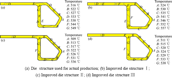
图10 采用不同模具结构计算的型材横断面的温度分布(挤压行程100 mm)
Fig. 10 Temperature distributions on cross section of profile calculated by various die structures (at stroke of 100 mm)
从挤压过程各质点的总温升情况来看,采用改进方案Ⅲ的模具结构时,质点P1、P2和P3的总温升分别为38、24和11 ℃,而采用现场模具结构时,质点P1的总温升分别为48、34和15 ℃。可以看到,采用改进方案Ⅲ的模具结构后,质点P1和P2的总温升均降低了10 ℃,而质点P3的总温升仅降低了4 ℃。由此可见,采用改进方案Ⅲ的模具结构后,质点P1的温升降低程度大于质点P3的,因而,型材横断面的最大温差减小。质点P1总温升降低的很大一部分贡献来自于其在分流孔内的温升降低,这主要是由于改进方案Ⅲ中主要对分流桥底部的模具结构进行了简化,金属流经分流桥底部时局部变形程度减小,导致变形抗力减小,因此,流经该处的金属质点P1发生塑性变形和摩擦产生的热量减少,温升降低。

图11 采用方案Ⅲ的模具结构计算的挤压过程各阶段P1~P3质点的温升
Fig. 11 Temperature rise of points P1-P3 at different stages of extrusion calculated by improved die structure Ⅲ
2.4 挤压工艺参数的影响
由于图1所示型材的横断面形状较为复杂,挤压过程中金属塑性变形本身存在不均匀性,从而导致塑性变形热的分布也具有不均匀性,因此,型材横断面的温度不均匀分布难以通过改进模具结构设计而完全改善。根据6000系铝合金挤压实际生产经验和生产条件[14],本文作者从坯料温度、坯料与挤压筒的温差和挤压速度3个方面,研究了挤压工艺参数对图1所示型材的横断面最大温差的影响。
所选择的挤压工艺参数为坯料初始温度500~550 ℃、挤压筒温度比坯料温度低10~50 ℃、挤压模具温度460 ℃、挤压速度1~5 mm/s。挤压工艺参数的选择方案如表1所示。其中,由方案1、2、3可分析挤压速度对型材横断面温差的影响,由方案1、4、5可分析坯料温度(在保证坯料与挤压筒温差相同的前提下)对型材横断面温差的影响,由方案1、6、7可分析坯料与挤压筒温差对型材横断面温差的影响。
采用图9中方案Ⅲ所示的模具结构设计方案建立有限元模型,根据表1中的挤压工艺参数分别进行模拟计算,可以得到模孔出口处型材横断面的最大温差,如表1最后两列数据所示(挤压行程100 mm和250 mm)。其中,挤压行程100 mm时方案1、3、5和6的型材横断面温度分布结果如图12所示。
由表1和图12的结果可以看到,当挤压速度由1 mm/s提高到5 mm/s时,挤压行程100 mm时的型材横断面最大温差由27 ℃上升至50 ℃,挤压行程250 mm时型材横断面的最大温差由32 ℃上升至59 ℃,表明提高挤压速度会使型材横断面最大温差增大,加剧型材的横断面温度不均匀性。同时,挤压速度提高后,模孔出口处型材的整体温度也明显升高,如图12(b)所示,当挤压速度为5 mm/s时,模孔出口处型材的局部最高温度达到6005铝合金的过烧温度(约610 ℃)[15],容易导致挤压型材组织过烧,严重影响型材的性能。
表1 挤压工艺参数选择方案
Table 1 Selection scheme of extrusion process parameters


图12 不同挤压工艺参数方案时型材横断面的温度分布(挤压行程100 mm)
Fig. 12 Temperature distributions on cross section of profile calculated by different extrusion process parameters (at stroke of 100 mm)
在坯料与挤压筒温差不变的前提下,当坯料温度由500 ℃提高至550 ℃时,挤压行程100 mm时,型材横断面的最大温差由27 ℃减小至24 ℃;挤压行程250 mm时,型材横断面的最大温差由32 ℃变为31 ℃,横断面最大温差有所降低但降低的幅度较小;当坯料与挤压筒的温差分别为10、30和50 ℃时,型材的横断面的最大温差基本保持不变。
以上研究表明,通过改进上模桥墩结构设计并合理匹配挤压工艺参数(如较低的挤压速度、较高的坯料温度),可使本实验中型材的横断面温度不均匀性得到一定的改善。例如,当模具结构采用图9(a)的现场设计方案,即挤压工艺参数为坯料温度500 ℃、挤压筒温度470 ℃、挤压速度3 mm/s时,挤压行程为250 mm时型材横断面的最大温差约为60 ℃(见图3);而当模具结构采用图9(d)的改进方案Ⅲ,即挤压工艺参数为坯料温度550 ℃、挤压筒温度520 ℃、挤压速度1 mm/s、挤压行程为250 mm时型材横断面的最大温差降为31 ℃,型材横断面的最大温差降低了50%左右,横断面温度的不均匀性得到明显改善。
3 结论
1) 采用质点逆向追踪方法,可获得型材横断面上任一位置处的质点在挤压过程的温度变化情况,分析挤压过程中不同阶段型材横断面温度分布不均匀性的情形。质点温度逆向追踪结果表明:挤压过程中质点在分流孔内流动时的温度变化对模孔出口处型材横断面温度分布不均匀性的影响较大,而在焊合室内和模孔内流动时的温度变化对其影响较小。
2) 挤压过程中各项热流对型材横断面温度分布不均匀性的影响程度由大到小依次为摩擦热、塑性变形热、金属与工模具之间的传热。为了改善型材横断面温度分布的不均匀性,应优先调控金属在分流孔内流动时的摩擦热和塑性变形热。
3) 挤压速度对型材横断面最大温差的影响较大,坯料温度和坯料与挤压筒的温差对型材横断面最大温差的影响较小。
4) 采用生产现场的模具结构设计方案,当坯料温度为500 ℃、挤压筒温度为470 ℃、挤压速度为3 mm/s时,型材横断面最大温差达60 ℃,而采用模具结构改进方案Ⅲ,即坯料温度550 ℃、挤压筒温度520 ℃、挤压速度1 mm/s的挤压工艺参数方案时,型材横断面最大温差降低到31 ℃,不均匀性明显改善。
REFERENCES
[1] SANABRIA V, MUELLER S, REIMERS W. Microstructure evolution of friction boundary layer during extrusion of AA6060 [J]. Procedia Engineering, 2014, 81: 586-591.
[2] TAKAHASHI M, YONEYAMA T. Isothermal extrusion of aluminum alloys[J]. Journal of the Japan Society for Technology of Plasticity, 2005, 46(532): 3-8.
[3] 谢建新, 刘静安. 金属挤压理论与技术[M]. 2版. 北京: 冶金工业出版社, 2012.
XIE Jian-xin, LIU Jing-an. Theory and technology for metal extrusion[M]. 2nd ed. Beijing: Metallurgical Industry Press, 2012.
[4] 张 君, 杨 合, 何养民, 韩炳涛, 詹 梅. 铝及铝合金型材等温挤压关键技术研究进展[J]. 重型机械, 2003(6): 1-5.
ZHANG Jun, YANG He, HE Yang-min, HAN Bing-tao, ZHAN Mei. Technical research and realization means of isothermal aluminium extrusion[J]. Heavy Machinery, 2003(6): 1-5.
[5] 李落星, 周 佳, 张 辉. 车身用铝、镁合金先进挤压成形技术及应用[J]. 机械工程学报, 2012, 48(18): 35-43.
LI Luo-xing, ZHOU Jia, ZHANG Hui. Advanced extrusion technology and application of aluminium, magnesium alloy for vehicle body[J]. Journal of Mechanical Engineering, 2012, 48(18): 35-43.
[6] 杨 武, 谭建平, 陈 晖. 挤压机速度控制系统建模及控制策略研究[J]. 锻压技术, 2013, 38 (6): 150-155.
YANG Wu, TAN Jian-ping, CHEN Hui. Research on control strategy and modeling of speed control system for extrusion press[J]. Forging and Stamping Technology, 2013, 38(6): 150-155.
[7] 李静媛, 谢建新, 宋 勇, 殷 实, 顾 伟. 铝镁合金预测模糊控制温度闭环等温挤压系统及方法: 中国, ZL 201110346836.3[P]. 2013-05-22.
LI Jing-yuan, XIE Jian-xin, SONG Yong, YIN Shi, GU Wei. The temperature closed loop isothermal extrusion system and method by using predictive fuzzy control for aluminum and magnesium alloy: China, ZL 201110346836.3[P]. 2013-05-22.
[8] 谢建新, 张志豪, 侯文荣, 李静媛. 一种工艺参数综合控制等温挤压的方法: 中国, ZL 201210088373.X[P]. 2014-03-26.
XIE Jian-xin, ZHANG Zhi-hao, HOU Wen-rong, LI Jing-yuan. An isothermal extrusion method by comprehensively controlling extrusion process parameters: China, ZL 201210088373.X[P]. 2014-03-26.
[9] 侯文荣, 张志豪, 谢建新, 陈蕴博. 铝合金空心型材分流模挤压成形全过程温度场的数值模拟[J]. 中国有色金属学报, 2013, 23(10): 2769-2778.
HOU Wen-rong, ZHANG Zhi-hao, XIE Jian-xin, CHEN Yun-bo. Numerical simulation of temperature field during whole extrusion process of aluminum hollow profile with porthole die extrusion forming[J]. The Chinese Journal of Nonferrous Metals, 2013, 23(10): 2769-2778.
[10] 谢建新, 黄东男, 李静媛, 张志豪. 一种空心型材分流模挤压焊合过程数值模拟技术: 中国, ZL 200910088960.7[P]. 2010-10-27.
XIE Jian-xin, HUANG Dong-nan, LI Jing-yuan, ZHANG Zhi-hao. A numerical simulation technology during the welding process of porthole die extrusion for hollow profile: China, ZL 20091008896.7[P]. 2010-10-27.
[11] 黄东男, 李静媛, 张志豪, 谢建新. 方形管分流模双孔挤压过程中金属的流动行为[J]. 中国有色金属学报, 2010, 20(3): 487-495.
HUANG Dong-nan, LI Jing-yuan, ZHANG Zhi-hao, XIE Jian-xin. Metal flowing behaviors during diplopore extrusion of square tube with porthole die[J]. The Chinese Journal of Nonferrous Metals, 2010, 20(3): 487-495.
[12] 黄东男, 张志豪, 李静媛, 谢建新. 焊合室深度及焊合角对方形管分流模双孔挤压成形质量的影响[J]. 中国有色金属学报, 2010, 20(5): 954-960.
HUANG Dong-nan, ZHANG Zhi-hao, LI Jing-yuan, XIE Jian-xin. Influences of welding chamber depth and welding angle on forming quality of extrusion of square tube by porthole die[J]. The Chinese Journal of Nonferrous Metals, 2010, 20(5): 954-960.
[13] ZHANG Z H, HOU W R, HUANG D N, XIE J X. Mesh reconstruction technology of welding process in 3D FEM simulation of porthole extrusion and its application[J]. Procedia Engineering, 2012, 36: 253-260.
[14] 肖亚庆, 谢水生, 刘静安, 王 涛. 铝加工技术实用手册[M]. 北京: 冶金工业出版社, 2004.
XIAO Ya-qing, XIE Shui-sheng, LIU Jing-an, WANG Tao. Aluminum processing technology practical manual[M]. Beijing: Metallurgical Industry Press, 2004.
[15] 张大新, 杨瑞成. 6005铝合金的过烧温度及其组织特征[J]. 轻合金加工技术, 2011, 39(4): 39-42.
ZHANG Da-xin, YANG Rui-cheng. Over heating temperature and microstructure characteristics of 6005 aluminum alloy[J]. Light Alloy Fabrication Technology, 2011, 39(4): 39-42.
(编辑 龙怀中)
基金项目:国家高技术研究发展计划资助项目(2013AA032402)
收稿日期:2014-10-20;修订日期:2015-04-25
通信作者:张志豪,副教授,博士;电话:010-62332253;E-mail:ntzzh2279@163.com

