Crashworthiness optimization design of foam-filled tapered decagonal structures subjected to axial and oblique impacts
��Դ�ڿ������ϴ�ѧѧ��(Ӣ�İ�)2019���10��
�������ߣ�PIRMOHAMMAD Sadjad AHMADI-SARAVANI Soheil ZAKAVI S. Javid
����ҳ�룺2729 - 2745
Key words��crashworthiness; foam-filled tapered structure; axial and oblique impact; RBF neural network and genetic algorithm; TOPSIS technique
Abstract: In this research, crashworthiness of polyurethane foam-filled tapered decagonal structures with different ratios of a/b=0, 0.25, 0.5, 0.75 and 1 was evaluated under axial and oblique impacts. These new designed structures contained inner and outer tapered tubes, and four stiffening plates connected them together. The parameter a/b corresponds to the inner tube side length to the outer tube one. In addition, the space between the inner and outer tubes was filled with polyurethane foam. After validating the finite element model generated in LS-DYNA using the results of experimental tests, crashworthiness indicators of SEA (specific energy absorption) and Fmax (peak crushing force) were obtained for the studied structures. Based on the TOPSIS calculations, the semi-foam filled decagonal structure with the ratio of a/b=0.5 demonstrated the best crashworthiness capability among the studied ratios of a/b. Finally, optimum thicknesses (t1 (thickness of the outer tube), t2 (thickness of the inner tube), t3 (thickness of the stiffening plates)) of the selected decagonal structure were obtained by adopting RBF (radial basis function) neural network and genetic algorithm.
Cite this article as: Pirmohammad Sadjad, Ahmadi-SARAVANI Soheil, Zakavi S. Javid. Crashworthiness optimization design of foam-filled tapered decagonal structures subjected to axial and oblique impacts [J]. Journal of Central South University, 2019, 26(10): 2729-2745. DOI: https://doi.org/10.1007/s11771-019-4209-1.

J. Cent. South Univ. (2019) 26: 2729-2745
DOI: https://doi.org/10.1007/s11771-019-4209-1

Pirmohammad Sadjad, Ahmadi-SARAVANI Soheil, Zakavi S. Javid
Department of Mechanical Engineering, University of Mohaghegh Ardabili, Ardabil 179, Iran
 Central South University Press and Springer-Verlag GmbH Germany, part of Springer Nature 2019
Abstract: In this research, crashworthiness of polyurethane foam-filled tapered decagonal structures with different ratios of a/b=0, 0.25, 0.5, 0.75 and 1 was evaluated under axial and oblique impacts. These new designed structures contained inner and outer tapered tubes, and four stiffening plates connected them together. The parameter a/b corresponds to the inner tube side length to the outer tube one. In addition, the space between the inner and outer tubes was filled with polyurethane foam. After validating the finite element model generated in LS-DYNA using the results of experimental tests, crashworthiness indicators of SEA (specific energy absorption) and Fmax (peak crushing force) were obtained for the studied structures. Based on the TOPSIS calculations, the semi-foam filled decagonal structure with the ratio of a/b=0.5 demonstrated the best crashworthiness capability among the studied ratios of a/b. Finally, optimum thicknesses (t1 (thickness of the outer tube), t2 (thickness of the inner tube), t3 (thickness of the stiffening plates)) of the selected decagonal structure were obtained by adopting RBF (radial basis function) neural network and genetic algorithm.
Key words: crashworthiness; foam-filled tapered structure; axial and oblique impact; RBF neural network and genetic algorithm; TOPSIS technique
Cite this article as: Pirmohammad Sadjad, Ahmadi-SARAVANI Soheil, Zakavi S. Javid. Crashworthiness optimization design of foam-filled tapered decagonal structures subjected to axial and oblique impacts [J]. Journal of Central South University, 2019, 26(10): 2729-2745. DOI: https://doi.org/10.1007/s11771-019-4209-1.
1 Introduction
The increasing interests on safety and crashworthiness have led to extensive investigations on crushing behavior of thin-walled structures with different cross sectional geometries. Many theoretical, experimental and numerical studies have been made on the straight single-walled columns during the past decades. For example, ABRAMOWICZ and JONES [1] conducted axial experiments on circular and square columns for investigating their crushing behavior. LANGSETH and HOPPERSTAD [2] studied effects of wall thicknesses and impact velocities on the crushing response of square tubes. ALEXANDER [3] theoretically calculated the collapse force of circular columns.
In another study, WIERZBICKI and ABRAMOWICZ [4] presented a formula for calculating the mean crushing force of square columns. PIRMOHAMMAD et al [5-7] performed numerical runs to evaluate crashworthiness of polygonal columns. TARLOCHAN et al [8] compared crushing behavior of several different cross sectional shapes of thin-walled structures subjected to direct and oblique loads. More recently, SUN et al [9, 10] presented some novel variable thickness thin-walled structures, and derived a uniform analytical model for their mean crushing forces.
The results show that the theoretical solutions agree well with the experimental results. According to their investigation, these novel structures can significantly improve the efficiency of material utilization for thin-walled structures and reduce the peak force. ALAVI-NIA et al [11] investigated crashworthiness capacity of simple and multi-cell thin-walled columns made of aluminum with triangular, square, hexagonal and octagonal cross- sections under quasi-static loading.
They observed that the octagonal and hexagonal multi-cell structures have the greatest energy absorbing characteristics. PIRMOHAMMAD and ESMAEILI- MARZDASHTI [12] made an investigation on the crushing response of multi-cell structures with different cross sections (namely triangular, square, hexagonal and circular), and reported that the circular multi-cell structure is more effective energy absorber than the studied structures particularly the single-cell structures. PIRMOHAMMAD et al [13, 14, 15] studied crushing behavior of multi-cell structures with various cross-sections. They concluded that the decagonal structure has the greatest crashworthiness capacity. WU et al [16] studied the effect of the number of cells and topological configurations of multi-cell structures on their crashworthiness experimentally and numerically. In another investigation performed by FANG et al [17], unlike the existing multi-cell tubes with a uniform thickness, they introduced a functionally graded thickness to multi-cell tubes. PIRMOHAMMAD and ESMAEILI- MARZDASHTI [18] investigated crashworthiness of novel multi-cell structures called combined straight-tapered columns to dissipate the collision energy. In order to further improve the energy absorption and design efficiency of multi-cell tubes, SUN et al [19-22] developed some novel optimization algorithms.
Frusta and tapered thin-walled structures have been also considered as effective energy absorbing devices by many researchers [23-27]. Generally, the tapered structures are preferable to the straight ones due to their effective crashworthiness responses under oblique loads where they show less global buckling mode. In addition, the tapered structures have more stable plastic behavior and less initial peak force than the straight structures under axial impact. Additionally, from a design point of view, tapered structures offer better energy absorption characteristics than the straight ones; because, they have a bigger design space [28]. GULER et al [29] compared the crashworthiness ability of tapered and straight structures with square, circular and hexagonal cross sections. According to their results, the tapered circular structure is the most efficient energy absorbing device among the studied geometries. MAMALIS and JOHNSON [30] reported that the deformation modes of tapered structures are similar to those of straight ones, where circular conical structures usually deform in either the diamond mode or concertina mode, depending on the geometry of the structure. In another study, NEGAL et al [25, 31] compared crashworthiness capacity of straight and tapered rectangular structures under quasi-static axial loading. LI et al [32] compared the energy absorption capabilities of functionally graded thickness (FGT), tapered uniform thickness (TUT) and straight uniform thickness (SUT) tubes subjected to oblique impact loading. They also derived analytical formula for the geometric relationships of these three different configurations (FGT, SUT and TUT). PIRMOHAMMAD et al [7] evaluated crushing behavior of double-cell conical tubes with polygonal cross-sections.
In another investigation, ZHANG et al [33, 34] optimized the geometrical dimensions of foam- filled columns, and concluded that the foam-filled tapered structure is an excellent energy absorber. HOSSEINI-TEHRANI et al [35] studied crushing behavior of several antisymmetric tapered tubes with an inner stiffener under axial and oblique loading, and the optimum dimensions of these tapered tubes were derived. SONG et al [36] carried out a comparative study on the different surrogate models, such as polynomial response surface (PRS), Kriging (KRG), support vector regression (SVR) and radial basis function (RBF), which have been widely used for a variety of engineering problems. In their study, a foam-filled tapered thin-walled structure is exemplified. Increasing the crashworthiness performance while maintaining a minimum mass have been the main challenge of researchers in the past decades. Distinguished idea for this is to use lightweight materials like reinforced polyamide, cork, wood, polyurethane foam and metal foam as a filler in thin-walled structures. These fillers deform largely at almost constant crash force and thus using them together with thin-walled structures to improve the energy absorption capacity of the filled structures.
Among the mentioned fillers, the metallic and polymeric foams have received increased attention as a new generation of lightweight materials with high potential for increasing crashworthiness capacity [28]. Polymeric foams are widely used as a filler material in thin-walled structures to improve their crashworthiness capability. Hence, they are frequently utilized in different structural components of automobiles, trains and so on. Many experimental [37-40], analytical [41-43] and numerical [44-47] studies can be found in the literature performed on the crushing behavior of foam-filled thin-walled structures. The early studies on the crushing behavior of foam-filled energy absorbers were conducted by REID et al [23, 48]. They used polyurethane foam as filler in square, rectangular and tapered structures. Afterwards, many researches were carried out on the energy absorbing behavior of such structures with different cross-sectional geometries including square [49-52], hexagonal and octagonal [51], circular [53-56], tapered rectangular and circular [44, 57-59]. YUEN et al [60] investigated the collapsing behavior of double-cell foam-filled columns. Their investigation concludes that the circular columns have greater energy absorption capacity than square ones. SUN et al [61] experimentally studied on the crashworthiness of empty/aluminum foam/ honeycomb-filled tubes. FANG et al [62] considered crushing behavior of bitubal circular columns filled with foam. ZHANG et al [63] made an optimization study on foam-filled bitubal tubes with square cross section. In an interesting task, ZHANG et al [64] proposed functionally graded foam to fill into functionally graded thickness thin-walled structure, named as double functionally graded (DFG) tube, where different configurations of foam and wall thickness gradients are taken into account. They finally recommend the DFG structure of Ascending�CAscending gradient for a potential absorber. ZHENG et al [65] compared the crashworthiness capacity of foam-filled single and bitubal polygonal columns subjected to longitudinal impact. According to their study, the foam-filled circular bitubal column is the best energy absorber among the studied columns. All of these investigations showed remarkable improvements in the crashworthiness capacity of the foam-filled thin-walled structures.
According to the researches reviewed above, the energy absorption capacities of foam-filled columns are highly affected by cross-sectional configurations and distribution of foam filler. On the other hand, the researchers employed optimization methods in recent years to further improve the energy absorption capacity of foam- filled multi-cell thin-walled structures. Hence, it appears necessary to seek the optimal design parameters for foam filled multicell structures. In this regard, the researchers have been undertaken on the optimization of foam filled multi-cell tubes. For example, YIN et al [66] optimized the foam-filled multi-cell columns under axial and oblique impacts. Later, YIN et al [67] performed multi objective optimization for foam-filled bionic column. GAO et al [68] optimized foam-filled double ellipse structure to achieve more suitable energy absorber. SUN et al [19] explored the topological design of multi-cell configuration and foam filler distribution for seeking optimal crashworthiness.
Generally, vehicle collision occurs under axial or oblique loadings. It is emphasized that a vehicle crash barely takes place under pure axial impact, and often occurs under oblique loading. Therefore, the collapse behavior of vehicle components must be evaluated under both the axial and oblique loads to obtain structures with desirable crashworthiness performance. Many investigations have been performed by researchers so far on the oblique impact loading (see Refs. [5, 20, 32, 58, 59]), which confirm significance of the investigations on the oblique impact of thin-walled structures.
2 Geometry of decagonal structures and FE modeling
Figure 1 shows geometry of the polyurethane foam-filled tapered decagonal structures. They consisted of inner and outer tubes connected together by several stiffeners. Five different ratios of a/b=0, 0.25, 0.5, 0.75 and 1, were assumed for the decagonal structures as seen in Figure 1. As is evident from Figure 1, the ratios of a/b=0 and a/b=1 correspond to simple foam-filled decagonal structure and single-cell decagonal structure, respectively; while, the other ratios of a/b correspond to the foam-filled tapered bitubal structures. The decagonal structures shown in Figure 1 were designated as D-x, where D refers to the decagonal structure and x represents the value of a/b. The thickness, length and tapered angle of these structures were 2 mm, 120 mm and ��=5��, respectively. Furthermore, perimeter of the external tube was taken 160 mm at the large end of the structures with different ratios of a/b.
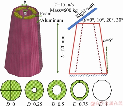
Figure 1 Foam-filled tapered decagonal structures with different ratios of a/b
It is worth mentioning that the die casting process may be used for the mass production of the tapered structures shown in Figure 1. For the small quantities, the decagonal structures used in this research can be fabricated from aluminum sheets, which are cut and bent to form every part of the decagonal structure, depending on the design. The final assembled structure can be made by welding the edges of the parts similar to the investigations performed by JUSUF et al [69] and VINAYAGAR and SENTHIL-KUMAR [70].
The boundary and impact conditions are shown in Figure 1, which the large end of structures was fixed in all directions, and the small end was assumed free. It was also assumed that a rigid box with the mass of 600 kg impacted onto the structures at an initial speed of 15 m/s. Meanwhile, the impact angles were assumed ��=0�� (axial impact) and ��=10��, 20��, 30��(oblique impacts). It is also noticed that the rigid box equally crushed the structures (i.e., 90 mm or 75% of the structure length).
Aluminum alloy AA6060 was used for the stiffeners, inner and outer tubes, whose material properties are: yield stress sy=80 MPa, ultimate stress su=173 MPa, elastic modulus E=68 GPa, Poisson��s ratio ��=0.33 and density r=2700 kg/m3. Plastic stress-strain behavior of AA6060 has been given in Figure 2(a). In addition, mechanical properties of the polyurethane foam are [71]: elastic modulus E=8.5 GPa, yield stress sy=1.24 MPa and density r=174 kg/m3. Figure 2(b) presents the stress-strain behavior of the polyurethane foam.
Crushing behavior of the decagonal structures was investigated by using the finite element code LS-DYNA. In order to construct mesh patterns of the decagonal structure walls, shell elements having five integration points through the thickness were employed. Furthermore, solid elements were employed for constructing mesh patterns of the foam. It is noticed that the mesh convergence analysis was adopted in LS-DYNA. Finally, the suitable element sizes were found 2 mm��2 mm��2 mm and 2 mm��2 mm for the solid and shell elements, respectively. AUTOMATIC-SINGLE- SURFACE algorithm was used in order not to penetrate decagonal structure walls into each other. Besides, AUTOMATIC-SURFACE-TO-SURFACE algorithm was employed to model the contact between the structure walls and foam.
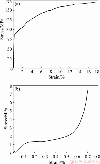
Figure 2 Stress-strain curve for the AA6060 (a) and stress-strain curve for the polyurethane foam (b)
Modified-Piecewise-Linear-Plasticity and Mat- Crushable-Foam codes were respectively used to define the mechanical properties of aluminum AA6060 and foam in LS-DYNA.
3 FE model validation
Finite element model constructed in LS-DYNA was validated using the experiments performed on the foam-filled bitubal square tube and the foam-filled circular tube. Both the foam-filled bitubal square tube and foam-filled circular tube were tested under axial impact. The bitubal square specimen had the inner and outer side widths, length and thickness of 30, 60, 150 and 1.8 mm, respectively; while, the radius, length and thickness for the circular specimen were 30, 100 and 1.8 mm, respectively (see Figure 3). Meanwhile, material properties for the tube walls and polyurethane foam are those presented in Section 2. The experiments upon these specimens were carried out using a free-fall drop hammer displayed in Figure 3(a).
The impact tests were performed such that the specimens were fixed upon a fixture, and afterwards a hammer with the mass of 250 kg dropped upon the specimens from 3.27 m height. The hammer speed at the moment of impact was 8 m/s. In the impact tests, force-displacement variations were recorded by load cell and data logger. Crash behavior of the foam-filled bitubal square tube and the foam-filled circular tube was simulated in LS-DYNA similar to the experiment conditions. Figures 3(a) and (b) show both the experimental and numerical results for the specimens described above. Based on the results given in Figure 3, good agreements were obtained between the experimental and numerical results in terms of the deformation modes and the force�Cdisplacement curves.
Consequently, the finite element model generated in LS-DYNA was capable of simulating the crushing behavior of foam filled structures with reasonable accuracy.
4 Results and discussions
4.1 Deformation modes and force-displacement curves
Collapse response of the decagonal structures shown in Figure 1 was evaluated using the experimentally validated FE model. Deformation modes for the decagonal structures with different rations of a/b have been given in Figure 4, in which the decagonal structures with the ratios of a/b=0, 0.75 and 1 showed progressive and diamond deformation mode; while, the decagonal structures with the ratios of a/b=0.25 and 0.5 collapsed in more effective progressive and concertina deformation mode under axial impact loading. This implies that the foam available in the structures with the ratios of 0.25 and 0.5 changed the deformation mode from diamond into concertina. It is also emphasized that the structure without the foam filler showed diamond deformation mode. On the other hand, all the decagonal structures demonstrated a mixed diamond and global bending mode, when they were subjected to the small oblique impact (namely ��=10��). This implies that similar to the axial impact, still more effective progressive deformation mode existed under oblique impact of ��=10��. For the greater oblique impacts (i.e., ��=20�� and ��=30��), all the decagonal structures deformed as global bending mode at the regions of incidental and distal ends.
Figure 5 plots the force-displacement curves obtained from LS-DYNA for the decagonal structures impacted under different loading angles. As seen in this figure, when the structures were subjected to the axial impact, the force firstly increased to reach its maximum value for generation of the first fold, and then oscillated several times for generating the subsequent folds. For the loading angle ��=10��, the force- displacement curve was the same as the one observed for the axial impact. However, some differences exist. In comparison to the axial impact, the force firstly enhanced on less steep as well as the maximum value of force was less. This is because the rigid box deformed only a small part of cross section of the decagonal structures at the beginning of the oblique impact. For the greater oblique impact angles (i.e., ��=20��and ��=30��), the force firstly enhanced to reach its peak value, and then sharply decreased because of the global bending deformations at the distal end of the decagonal structures.
4.2 Crashworthiness criteria
In order to evaluate the crashworthiness capacity, several criteria have been introduced so far. SEA (specific energy absorption) is the important one, which can be calculated from the following equation:
 (1)
(1)
where Ea is the energy absorption of a tube. This can be obtained by integrating the area under the force-displacement curve. Besides, ��i is the total crushing displacement, �� is the instantaneous crushing displacement, mt is the total mass of tube, and F(��) is the instantaneous crushing force.Indeed, SEA is a measure of energy absorption capability, so the higher SEA states the more energy absorption capacity.
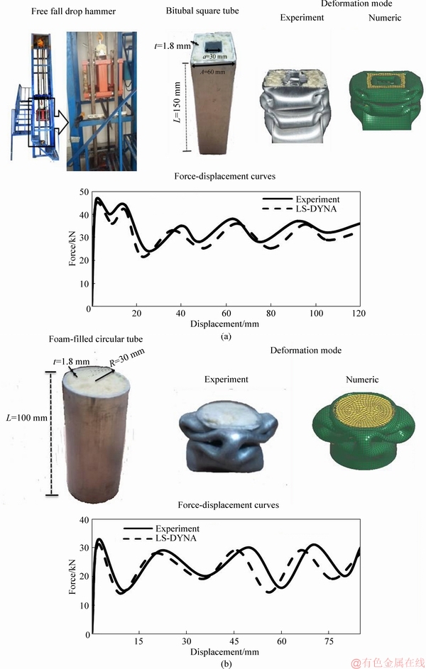
Figure 3 Experimental and numerical results for bitubal square structure (a) and circular tube (b)
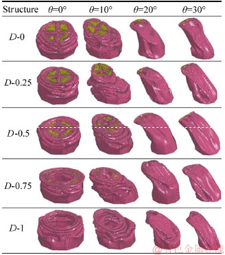
Figure 4 Deformation modes for foam-filled tapered decagonal structures under different impact angles
Values of the SEA for the foam-filled decagonal structures studied in this task have been shown in Figure 6(a). For all the impact angles, as the ratio of a/b increased, the SEA enhanced to reach its peak value at a/b=0.5, and then reduced as seen in Figure 6(a). Besides, as the impact angle increased, the SEA reduced because of turning the crushing mode from progressive folding to the global bending. It is noticed that the bending mode is an inefficient crushing mode which absorbs less energy compared with the progressive deformation mode.
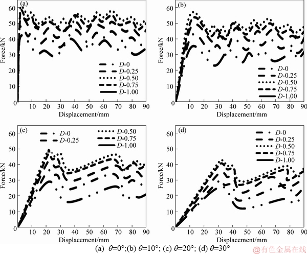
Figure 5 Force-displacement curves for foam-filled tapered decagonal structures under impact angles:
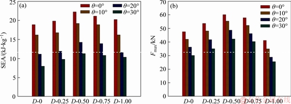
Figure 6 Crashworthiness criteria of SEA (a) and Fmax (b), for decagonal structures
Fmax (peak crushing force) is another key parameter for evaluating the crashworthiness of thin-walled structures. Indeed, Fmax is the maximum force observed in the crushing process of thin-walled structures. In the case of axial impact, Fmax corresponds to the initial peak force; while, it is not usually the initial peak force for the oblique impacts. However, value of Fmax must be kept below an allowable value to avoid the passengers from severe injuries during a collision. Figure 6(b) plots the values of Fmax for the foam-filled decagonal structures. As the ratio of a/b increased, the value of Fmax enhanced to reach its peak value at a/b=0.5, and then decreased. Besides, as the impact angle increased, the Fmax reduced due to changing deformation mode from the progressive folding into the global bending.
4.3 Selection of best structure
A decision-making technique called TOPSIS (technique for ordering preferences by similarity to ideal solution) was used in this research to find suitable ratio of a/b for the foam-filled tapered decagonal structures. The crashworthiness indicators, SEA and Fmax, under different impact angles obtained from the numerical analyses were used as criteria for comparing the decagonal structures in terms of crashworthiness capacity. Two artificial alternatives (namely ideal alternative with the best level of crashworthiness indicators and negative ideal alternative with the worst level of crashworthiness indicators) are considered in the TOPSIS calculations. Finally, the alternative closest to the ideal alternative and farthest from the negative ideal alternative is selected as the best choice from the TOPSIS calculations. More details concerning the TOPSIS technique have been given in Ref. [13].
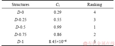
Numerical results presented in Figure 6 were used as the input data for TOPSIS calculations. As mentioned earlier, eight criteria (two crashworthiness indicators, SEA and Fmax under four impact angles) were considered in the present research to compare the decagonal structures with each other. As is well known, SEA and Fmax are respectively considered as the positive and negative parameters in the crashworthiness design of vehicle components, so a suitable energy absorbing device is expected to have higher value of SEA and lower value of Fmax. Besides, because SEA is more important than Fmax; therefore, their weights were considered 0.6 and 0.4, respectively in the TOPSIS calculations. Tables 1-3 show results of TOPSIS for the foam-filled tapered decagonal structures. Based on Table 1, ranking of the structures was finally found as: D-0.5>D-0.75>D-0.25>D-0>D-1. In other words, the foam-filled tapered decagonal structure with the ratio of a/b=0.5 was found as the best energy absorber. This implies that neither the structure fully filled with foam nor the empty one showed an appropriate crashworthiness capacity, but the semi-foam filled decagonal structure, namely D-0.5, demonstrated higher crashworthiness capability. Obviously, foam consumption and weight are significantly diminished by using the stiffened bitubal decagonal structure with a/b=0.5. Meanwhile, the single-cell decagonal structure, i.e., D-1, was found as the worst energy absorber from the TOPSIS calculations. As a result, the interaction between the foam and structure walls contributed to the crashworthiness enhancement. In other words, the presence of foam-filler within the decagonal structures produced more resistance to outward and inward folding during the collapsing process.
Table 1 Decision making matrix obtained for tapered decagonal structures
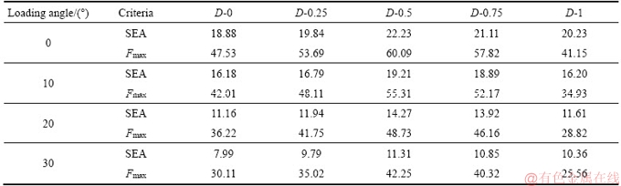
Table 2 Normalized decision-making matrix obtained for tapered decagonal structures
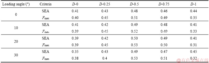
Table 3 Ranking results for tapered decagonal structures
Additionally, the interfacial friction between the foam and the structure walls improved the crashworthiness capacity of the foam-filled tapered decagonal structures.
5 Multi-objective optimization
After a decision-making process, the foam- filled tapered decagonal structure with the ratio of a/b=0.5 was selected as the most efficient cross sectional configuration. In this section, dimensions of this structure are optimized for further enhancing the crashworthiness capacity. Hence, the thicknesses of the inner and outer tubes together with the thickness of the stiffening plates are optimized herein using radial basis function (RBF) neural network. In this research, the RBF model was selected based on an investigation performed by WU et al [16].
Indeed, they compared the accuracies of RBF, RSM (response surface method) and KRG (Kriging) models for dual objectives of Fmax and SEA, and finally concluded that the RBF is the suitable surrogate model for the design optimization problems. Figure 7 presents the flowchart of the optimization process. The abovementioned crashworthiness indicators, i.e., SEA and Fmax, were considered as the criteria in the optimization process. A suitable energy absorber must have greater SEA and smaller Fmax, as mentioned above. Hence, the optimization problem considered in this research is defined as below:
 (2)
(2)
According to Eq. (2), t1, t2 and t3 are thicknesses of the outer tube, inner tube and stiffening plates of the decagonal structure, respectively. Indeed, theses parameters are regarded as design variables in the optimization problem, and they are obtained by maximizing SEA and minimizing Fmax. It is worth mentioning that the thickness of thin-walled structures is in the range between 1.5 mm and 3 mm, based on the previous studies. Therefore, thickness of the decagonal structure walls was varied in the mentioned rang.
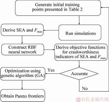
Figure 7 Flowchart of optimization process
An ANN (artificial neural network) is an information processing pattern that has been inspired by biological nervous systems. ANN is made up of various interconnected processing elements (i.e., neurons) to solve complicated nonlinear problems. An ANN is adjusted for a specific problem through a learning process.
RBF (radial basis function) neural network is a kind of neural network that learns via a supervised training method [72]. LOWE [73] was the first to use RBF in the design of neural networks. In radial functions, the response varies (decreases or increases) monotonically with distance from a center point [74]. RBF neural network is made up of three different layers: an input layer, an output layer and a hidden layer. Figure 8 displays the structure of RBF neural network. Unlike other ANNs, the hidden layer of RBF has only one layer, and each layer includes several neurons. The hidden layer connects the input and output layers together. According to Figure 8, the X=[x1, x2, ��, xn] and Y=[y1, y2, ��, ym] are the input and output vectors, respectively. The basis function for the jth hidden node is defined using Gaussian exponential function as follows:
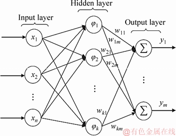
Figure 8 Structure of RBF neural network
 (3)
(3)
 ��+
��+
 (4)
(4)
where ��j is the width of the jth neuron, and ��j is the center of the jth neuron, which is a vector whose dimension is equal to the number of inputs to the neuron j.
The output vector Y is defined as the linearly weighted sum of the number of activation functions in the hidden layer:
 (5)
(5)
where ym is the mth output in the output layer, Wjm is the weight from the jth hidden layer neuron to the mth output layer neuron, and ��j is the output of the jth node in the hidden layer.
As seen in the abovementioned structure, the relation between the input layer and the hidden layer is nonlinear [72].
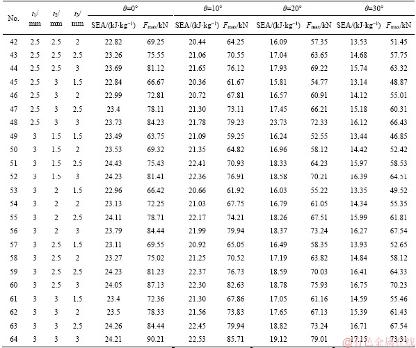
In the first step of constructing the RBF network, the input and output data must be provided. Thicknesses of t1, t2 and t3 were taken as the input data, while the values of SEA and Fmax were regarded as the output data. A series of sample points, (t1, t2 and t3), were selected from the design domain described in Eq. (2) to provide the input and output data. Four-level full factorial design within the design space of t1, t2 and t3 was implemented to select the sample points. Hence,64(=4��4��4) sample points were chosen as shown in Table 4. The foam-filled decagonal structures generated from these 64 sample points were analyzed in LS-DYNA under axial and three oblique impact angles (i.e., 256 analyses), and the crashworthiness indicators of SEA and Fmax were computed. They were regarded as the output data (see Table 4).
Table 4 Sample points together with corresponding crashworthiness indicators under different impact angles

to be continued
Continued
Construction of the RBF neural network contains two operating modes of training and testing. Training an RBF network is done in order to determine the number of RBFs, the corresponding centers and the output layer weight matrix. In training process of an RBF network, determination of the positions of node centers of kernel functions is crucial, because the outputs of the kernel functions produce information that is necessary for generalization capabilities of the RBF neural network. Meanwhile, the most commonly used algorithm namely k-means clustering was employed in this research to find the centers of RBF nodes in the hidden layer [72]. It is noticed that about seventy percent of the data given in Table 4 were used for training process of the RBF network, and the left thirty percent were used for testing process.
In order to construct the RBF network for optimizing the foam-filled decagonal structure, three and two neurons were considered for defining the input data (namely t1, t2 and t3) and output data (namely SEA and Fmax), respectively. The number of neurons in the hidden layer is the key parameter influencing the prediction capabilities of the RBF network. On the other hand, there is no procedure for determining the optimal number of hidden neurons. A trial and error method was used in this research for determining this number. In other words, various numbers of hidden neurons were tested, and the network with the best predictive capability was selected. The number of hidden neurons was finally found 25.
Performance of the RBF network constructed in this research was evaluated by mean square error (MSE), which can be calculated as:
 (6)
(6)
where m,  and yi correspond to the number of data set, numerical result, and the output value predicted by the constructed RBF network.
In order to maximize or minimize the objective functions obtained for the crashworthiness indicators of SEA and Fmax, multi-objective optimization was adopted in this research. It is worth mentioning that the non-linear objective functions for the crashworthiness indicators of SEA and Fmax in terms of the design variables (t1, t2 and t3) are obtained from the constructed RBF. A technique of mixed RBF network and genetic algorithm (GA), RBF-GA, was employed in this research to find optimum values of t1, t2 and t3.
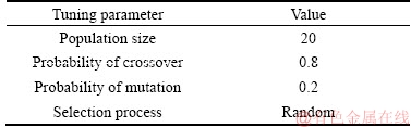
The GA technique with the adjusting parameters given in Table 5 was used to obtain the Pareto frontiers. The GA is inspired by Darwin��s theory on evolution. An intelligent exploitation of a random search is used in the GA technique to solve optimization problems. GA applies historical data to obtain an appropriate performance within the search space [75, 76].
Table 5 Tuning parameters for constructing RBF network
The optimization process was made on the foam-filled tapered decagonal structure with the ratio of 0.5 under different single impact angles (0��, 10��, 20�� and 30��) separately, as listed in Table 6. In other words, only one impact angle was regarded in each case. Pareto frontiers are shown in Figures 9(a)-(d). They have been plotted in terms of the two conflicting crashworthiness criteria, SEA and Fmax.
6 Conclusions
This research focused on the crashworthiness capability of the polyurethane foam-filled tapered decagonal structures with different ratios of a/b under axial and oblique impacts. Two crashworthiness criteria, SEA and Fmax were considered for the comparison of these structures. Using experimentally validated numerical models, the following important results are drawn:
1) The tapered decagonal structures with the ratios of a/b=0, 0.75 and 1 showed progressive and diamond deformation mode; while, those with the ratios of a/b=0.25 and 0.5 collapsed in more effective progressive and concertina deformation mode under axial impact loading. On the other hand, all the decagonal structures demonstrated a mixed diamond and global bending mode, when they were subjected to the small oblique impact (i.e. ��=10��). For the greater oblique impacts (i.e. ��=20��and ��=30��), all the decagonal structures deformed as global bending mode at the regions of incidental and distal ends.
2) For all the impact angles, as the ratio of a/b increased, both the SEA and Fmax enhanced to reach its peak value at a/b=0.5, and then reduced. Besides, as the impact angle increased, the values of SEA and Fmax reduced due to turning the crushing mode from progressive folding to the global bending.
3) According to the results of TOPSIS calculations, ranking of the foam-filled tapered decagonal structures was finally found as: D-0.5> D-0.75>D-0.25>D-0>D-1. In other words, the foam-filled tapered decagonal structure with the ratio of a/b=0.5 was found as the best energy absorber. This indicates that neither the structure fully filled with foam nor the empty one showed an appropriate crashworthiness capacity, but the semi-foam filled tapered decagonal structure namely D-0.5 demonstrated higher crashworthiness capability. Obviously, foam consumption and weight are significantly diminished by using the stiffened bitubal decagonal structure with a/b=0.5. Meanwhile, the single-cell decagonal structure, i.e., D-1, was found as the worst energy absorber from the TOPSIS calculations.
4) Thicknesses of the foam-filled tapered decagonal structure with the ratio of a/b=0.5 were optimized by adopting RBF neural network and genetic algorithm. The optimum values of thicknesses were obtained through two approaches namely i) the individual impact angle, ii) considering all the impact angles. The second approach was conducted because the optimal structure calculated from the first approach may perform worse when subjecting to other impact angles. Hence, the optimal structure calculated from the second approach can generally perform well under any single impact angle.
Table 6 Optimal decagonal structure predicted by RBF-GA and finite element results under different loading angles

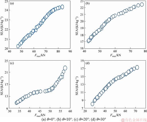
Figure 9 Pareto frontiers for foam-filled tapered decagonal structure with ratio of a/b=0.5 under different impact angles:
Acknowledgments
This research project has been financially supported by the Office of Vice Chancellor for Research under a research grant of Project No.: 1365-96/7/22 from University of Mohaghegh Ardabili. This support is gratefully acknowledged.
References
[1] Abramowicz W, Jones N. Dynamic progressive buckling of circular and square tubes [J]. International Journal of Impact Engineering, 1986, 4: 243-270.
[2] Langseth M, Hopperstad O. Static and dynamic axial crushing of square thin-walled aluminium extrusions [J]. International Journal of Impact Engineering, 1996, 18: 949-968.
[3] Alexander J. An approximate analysis of the collapse of thin cylindrical shells under axial loading [J]. The Quarterly Journal of Mechanics and Applied Mathematics, 1960, 13: 10-15.
[4] Wierzbicki T, Abramowicz W. On the crushing mechanics of thin-walled structures [J]. Journal of Applied Mechanics, 1983, 50: 727-734.
[5] Hosseini-Tehrani P, Pirmohammad S. Collapse study of thin-walled polygonal section columns subjected to oblique loads [J]. Proceedings of the Institution of Mechanical Engineers Part D: Journal of Automobile Engineering, 2007, 221: 801-810.
[6] Hosseini-Tehrani P, Pirmohammad S. Collapse study of a pair thin-walled prismatic column subjected to oblique loads [J]. Int J Auto Eng, 2011, 1: 267-279.
[7] PIRMOHAMMAD S, EKBATAN M H, ESMAEILI- Marzdashti S. Crashworthiness of double-cell conical tubes with different cross sections subjected to dynamic axial and oblique loads [J]. Journal of Central South University, 2018, 25: 632-645.
[8] Tarlochan F, Samer F, Hamouda A, Ramesh S, Khalid K. Design of thin wall structures for energy absorption applications: Enhancement of crashworthiness due to axial and oblique impact forces [J]. Thin-Walled Structures, 2013, 71: 7-17.
[9] Sun G, Pang T, Xu C, Zheng G, Song J. Energy absorption mechanics for variable thickness thin-walled structures [J]. Thin-Walled Structures, 2017, 118: 214-228.
[10] Zheng G, Pang T, Sun G, Wu S, Li Q. Theoretical, numerical, and experimental study on laterally variable thickness (LVT) multi-cell tubes for crashworthiness [J]. International Journal of Mechanical Sciences, 2016, 118: 283-297.
[11] ALAVI-Nia A, Parsapour M. Comparative analysis of energy absorption capacity of simple and multi-cell thin-walled tubes with triangular, square, hexagonal and octagonal sections [J]. Thin-Walled Structures, 2014, 74: 155-165.
[12] Pirmohammad S, ESMAEILI-Marzdashti S. Crushing behavior of new designed multi-cell members subjected to axial and oblique quasi-static loads [J]. Thin-Walled Structures, 2016, 108: 291-304.
[13] Pirmohammad S, Nikkhah H. Crashworthiness investigation of bitubal columns reinforced with several inside ribs under axial and oblique impact loads [J]. Proceedings of the Institution of Mechanical Engineers, Part D: Journal of Automobile Engineering, 2018, 232(3): 367-383.
[14] Pirmohammad S, AHMADI-Saravani S. Crashworthiness performance of stiffened foam-filled tapered structures under axial and oblique dynamic loads [J]. Latin American Journal of Solids and Structures, 2018, 15(5): 1-21.
[15] PIRMOHAMMAD S, ESMAEILI-MARZDASHTI S.Multi- objective optimization of multi-cell conical structures under dynamic loads [J]. Journal of Central South University, 2019, 26(9): 2464-2481.
[16] Wu S, Zheng G, Sun G, Liu Q, Li G, Li Q. On design of multi-cell thin-wall structures for crashworthiness [J]. International Journal of Impact Engineering, 2016, 88: 102-117.
[17] Fang J, Gao Y, Sun G, Zheng G, Li Q. Dynamic crashing behavior of new extrudable multi-cell tubes with a functionally graded thickness [J]. International Journal of Mechanical Sciences, 2015, 103: 63-73.
[18] Pirmohammad S, ESMAEILI-Marzdashti S. Crashworthiness optimization of combined straight-tapered tubes using genetic algorithm and neural networks [J]. Thin-Walled Structures, 2018, 127: 318-332.
[19] Sun G, Liu T, Huang X, Zhen G, Li Q. Topological configuration analysis and design for foam filled multi-cell tubes [J]. Engineering Structures, 2018, 155: 235-250.
[20] Sun G, Liu T, Fang J, Steven G P, Li Q. Configurational optimization of multi-cell topologies for multiple oblique loads [J]. Structural and Multidisciplinary Optimization, 2018, 57: 469-488.
[21] Fang J, Sun G, Qiu N, Steven GP, Li Q. Topology optimization of multicell tubes under out-of-plane crushing using a modified artificial bee colony algorithm [J]. Journal of Mechanical Design, 2017, 139: 071403.
[22] Sun G, Pang T, Fang J, Li G, Li Q. Parameterization of criss-cross configurations for multiobjective crashworthiness optimization [J]. International Journal of Mechanical Sciences, 2017, 124: 145-157.
[23] Reid S, Reddy T, Gray M. Static and dynamic axial crushing of foam-filled sheet metal tubes [J]. International Journal of Mechanical Sciences, 1986, 28: 295-322.
[24] Alghamdi A. Reinversion of aluminium frustra [J]. Thin-walled structures, 2002, 40: 1037-1049.
[25] Nagel G M, Thambiratnam D P. Dynamic simulation and energy absorption of tapered thin-walled tubes under oblique impact loading [J]. International Journal of Impact Engineering, 2006, 32: 1595-1620.
[26] Nagel G, Thambiratnam D. A numerical study on the impact response and energy absorption of tapered thin-walled tubes [J]. International Journal of Mechanical Sciences, 2004, 46: 201-216.
[27] PIRMOHAMMAD S, ESMAEILI-MARZDASHTI S. Multi- objective crashworthiness optimization of square and octagonal bitubal structures including different hole shapes [J]. Thin-Walled Structures, 2019, 139: 126-138.
[28] Baroutaji A, Sajjia M, Olabi A G. On the crashworthiness performance of thin-walled energy absorbers: Recent advances and future developments [J]. Thin-Walled Structures, 2017, 118: 137-163.
[29] Guler M A, Cerit M E, Bayram B, Gerceker B, Karakaya E. The effect of geometrical parameters on the energy absorption characteristics of thin-walled structures under axial impact loading [J]. International Journal of Crashworthiness, 2010, 15: 377-390.
[30] Mamalis A, Johnson W. The quasi-static crumpling of thin-walled circular cylinders and frusta under axial compression [J]. International Journal of Mechanical Sciences, 1983, 25: 713-732.
[31] Nagel G, Thambiratnam D. Computer simulation and energy absorption of tapered thin-walled rectangular tubes [J]. Thin-walled Structures, 2005, 43: 1225-1242.
[32] Li G, Xu F, Sun G, Li Q. A comparative study on thin-walled structures with functionally graded thickness (FGT) and tapered tubes withstanding oblique impact loading [J]. International Journal of Impact Engineering, 2015, 77: 68-83.
[33] Zhang Y, Sun G, Li G, Luo Z, LiQ. Optimization of foam-filled bitubal structures for crashworthiness criteria [J]. Materials & Design, 2012, 38: 99-109.
[34] Zhang Y, Sun G, Xu X, Li G, Li Q. Multiobjective crashworthiness optimization of hollow and conical tubes for multiple load cases [J]. Thin-Walled Structures, 2014, 82: 331-342.
[35] Hosseini-Tehrani P, Pirmohammad S, Golmohammadi M. Study on the collapse of tapered tubes subjected to oblique loads [J]. Proceedings of the Institution of Mechanical Engineers, Part D: Journal of Automobile Engineering, 2008, 222: 2025-2039.
[36] Song X, Sun G, Li G, Gao W, Li Q. Crashworthiness optimization of foam-filled tapered thin-walled structure using multiple surrogate models [J]. Structural and Multidisciplinary Optimization, 2013, 47: 221-231.
[37] Meguid S, Attia M, Monfort A. On the crush behaviour of ultralight foam-filled structures [J]. Materials & Design, 2004, 25: 183-189.
[38] Reyes A, Hopperstad O, Langseth M. Aluminum foam-filled extrusions subjected to oblique loading: Experimental and numerical study [J]. International Journal of Solids and Structures, 2004, 41: 1645-1675.
[39] Mamalis A, Manolakos D, Ioannidis M, Spentzas K, Koutroubakis S. Static axial collapse of foam-filled steel thin-walled rectangular tubes: Experimental and numerical simulation [J]. International Journal of Crashworthiness, 2008, 13: 117-126.
[40] Seitzberger M, RAMMERSTORFER F G, DEGISCHER H P, GRADINGER R. Crushing of axially compressed steel tubes filled with aluminium foam [J]. Acta Mechanica, 1997, 125: 93-105.
[41] Wang Q, Fan Z, Gui L. Theoretical analysis for axial crushing behaviour of aluminium foam-filled hat sections [J]. International Journal of Mechanical Sciences, 2007, 49: 515-521.
[42] Niknejad A, Liaghat G, Naeini HM, Behravesh A. Theoretical and experimental studies of the instantaneous folding force of the polyurethane foam-filled square honeycombs [J]. Materials & Design, 2011, 32: 69-75.
[43] Gupta N, Velmurugan R. Axial compression of empty and foam filled composite conical shells [J]. Journal of Composite Materials, 1999, 33: 567-591.
[44] Ahmad Z, Thambiratnam D. Crushing response of foam-filled conical tubes under quasi-static axial loading [J]. Materials & design, 2009, 30: 2393-2403.
[45] Ziaei-Rad S, Salimi M, Mirfendereski L. Finite element modelling of foam-filled tapered thin-walled rectangular tubes under oblique impact loading [J]. Steel Research International, 2008: 317-324.
[46] Santosa S, Banhart J, Wierzbicki T. Experimental and numerical analyses of bending of foam-filled sections [J]. Acta Mechanica, 2001, 148: 199-213.
[47] Fang J, Gao Y, An X, Sun G, Chen J, Li Q. Design of transversely-graded foam and wall thickness structures for crashworthiness criteria [J]. Composites Part B: Engineering, 2016, 92: 338-349.
[48] Reid S, Reddy T. Static and dynamic crushing of tapered sheet metal tubes of rectangular cross-section [J]. International Journal of Mechanical Sciences, 1986, 28: 623-637.
[49] Hanssen A G, Langseth M, Hopperstad O S. Static and dynamic crushing of circular aluminium extrusions with aluminium foam filler [J]. International Journal of Impact Engineering, 2000, 24: 475-507.
[50] Santosa S P, Wierzbicki T, Hanssen A G, Langseth M. Experimental and numerical studies of foam-filled sections [J]. International Journal of Impact Engineering, 2000, 24: 509-534.
[51] Seitzberger M, Rammerstorfer F G, Gradinger R, Degischer H, Blaimschein M, Walch C. Experimental studies on the quasi-static axial crushing of steel columns filled with aluminium foam [J]. International Journal of Solids and Structures, 2000, 37: 4125-4147.
[52] Zarei H, Kroger M. Optimization of the foam-filled aluminum tubes for crush box application [J]. Thin-Walled Structures, 2008, 46: 214-221.
[53] Kavi H, Toksoy A K, Guden M. Predicting energy absorption in a foam-filled thin-walled aluminum tube based on experimentally determined strengthening coefficient [J]. Materials & Design, 2006, 27: 263-269.
[54] Toksoy A K, G��den M. The strengthening effect of polystyrene foam filling in aluminum thin-walled cylindrical tubes [J]. Thin-walled Structures, 2005, 43: 333-350.
[55] Yan W, Durif E, Yamada Y, Wen C e. Crushing simulation of foam-filled aluminium tubes [J]. Materials Transactions, 2007, 48: 1901-1906.
[56] Zhu G, Li S, Sun G, Li G, Li Q. On design of graded honeycomb filler and tubal wall thickness for multiple load cases [J]. Thin-walled Structures, 2016, 109: 377-389.
[57] Mirfendereski L, Salimi M, Ziaei-Rad S. Parametric study and numerical analysis of empty and foam-filled thin-walled tubes under static and dynamic loadings [J]. International Journal of Mechanical Sciences, 2008, 50: 1042-1057.
[58] Ahmad Z, Thambiratnam D, Tan A. Dynamic energy absorption characteristics of foam-filled conical tubes under oblique impact loading [J]. International Journal of Impact Engineering, 2010, 37: 475-488.
[59] XiangZ, Guang-junG, JieZ, Xi-saiZ, WeiC, Wei- yuanG. A comparative crashworthiness analysis of multi-cell polygonal tubes under axial and oblique loads [J]. Journal of Central South University, 2017, 24(9): 2198-2208.
[60] Yuen S C K, Nurick G, Starke R. The energy absorption characteristics of double-cell tubular profiles [J]. Latin American Journal of Solids and Structures, 2008, 5: 289-317.
[61] Sun G, Li S, Liu Q, Li G, Li Q. Experimental study on crashworthiness of empty/aluminum foam/honeycomb-filled CFRP tubes [J]. Composite Structures, 2016, 152: 969-993.
[62] Fang J, Gao Y, Sun G, Zhang Y, Li Q. Crashworthiness design of foam-filled bitubal structures with uncertainty [J]. International Journal of Non-Linear Mechanics, 2014, 67: 120-132.
[63] Zhang Y, Sun G, Li G, Luo Z, Li Q. Optimization of foam-filled bitubal structures for crashworthiness criteria [J]. Materials & Design, 2012, 38: 99-109.
[64] Lu M, Sun G, Li G, Li Q. On functionally graded composite structures for crashworthiness [J]. Composite Structures, 2015, 132: 393-405.
[65] Zheng G, Wu S, Sun G, Li G, Li Q. Crushing analysis of foam-filled single and bitubal polygonal thin-walled tubes [J]. International Journal of Mechanical Sciences, 2014, 87: 226-240.
[66] Yin H, Wen G, Liu Z, Qing Q. Crashworthiness optimization design for foam-filled multi-cell thin-walled structures [J]. Thin-Walled Structures, 2014, 75: 8-17.
[67] Yin H, Xiao Y, Wen G, Gan N, Chen C, Dai J. Multi-objective robust optimization of foam-filled bionic thin-walled structures [J]. Thin-Walled Structures, 2016, 109: 332-343.
[68] Gao Q, Wang L, Wang Y, Guo F, Zhang Z. Optimization of foam-filled double ellipse tubes under multiple loading cases [J]. Advances in Engineering Software, 2016, 99: 27-35.
[69] Jusuf A, Dirgantara T, Gunawan L, Putra I S. Crashworthiness analysis of multi-cell prismatic structures [J]. International Journal of Impact Engineering, 2015, 78: 34-50.
[70] Vinayagar K, Kumar A S. Crashworthiness analysis of double section bi-tubular thin-walled structures [J]. Thin-walled Structures, 2017, 112: 184-193.
[71] Rezvani M J, Jahan A. Effect of initiator, design, and material on crashworthiness performance of thin-walled cylindrical tubes: A primary multi-criteria analysis in lightweight design [J]. Thin-walled Structures, 2015, 96: 169-182.
[72] Zhang A, Zhang L. RBF neural networks for the prediction of building interference effects [J]. Computers & Structures, 2004, 82: 2333-2339.
[73] Lowe D. Multi-variable functional interpolation and adaptive networks [J]. Complex Systems, 2: 321-355.
[74] Park J, Sandberg IW. Universal approximation using radial-basis-function networks [J]. Neural Computation, 1991, 3: 246-257.
[75] Rawlins G. Foundations of genetic algorithms [M]. Los Altos, CA: Morgan Kaufmann, 1991.
[76] Mitchell M. An introduction to genetic algorithms [M]. Cambridge, MA. USA: MIT Press, 1998.
(Edited by HE Yun-bin)
���ĵ���
��ĭ�����ʮ����ṹ�������б�����µ���ײ���Ż����
ժҪ�����о�������a/b=0�� 0.25��0.5��0.75��1�ľ۰�����ĭ�����ʮ����ṹ�������б�����µ���ײ�ԡ���Щ����ƵĽṹ�����ڲ����ⲿ�ιܺ��ĸ���ǿ�彫����������һ�𡣲���a/b��Ӧ����̥�����̥������⣬�����֮��Ŀռ�����˾۰�����ĭ��������������LS-DYNA����������Ԫģ�ͽ�������֤���õ����о��ṹ��SEA(�����ܱ�)��Fmax(��ֵ������)����ײ��ָ�ꡣ����TOPSIS�ļ��㣬a/b=0.5�İ���ĭ���ʮ����ṹ���ֳ���ѵ���ײ���ܡ�����þ����������������Ŵ��㷨�ֱ�õ���ѡʮ����ṹ����Ѻ��(��ܺ��t1���ڹܺ��t2����ǿ����t3)��
�ؼ��ʣ���ײ�ԣ������νṹ�������б����ײ��RBF���������Ŵ��㷨��TOPSIS��
Foundation item: Project(1365-96/7/22) supported by University of Mohaghegh Ardabili, Iran
Received date: 2018-01-09; Accepted date: 2018-11-13
Corresponding author: PIRMOHAMMAD Sadjad, PhD, Associate Professor; Tel: +98-4533515730; E-mail: s_pirmohammad@ uma.ac.ir

