
Parametric effect of large impulse current excited coil on electromagnetic force in coil-sheet system
XU Wei(许 威)1, 2, 3, FANG Hong-yuan(方洪渊)4, CAO Jun(曹 军)1,
DING Wen-bin(丁文斌)1, SHAN Ping(单 平)3
1. School of Material Science and Engineering, Tianjin University, Tianjin 300072, China;
2. Technology Department of Offshore Oil, Offshore Oil Engineering Company Ltd., Tianjin 300451, China;
3. Research Center of China Offshore Oil Corporation, Beijing 100027, China;
4. State Key Laboratory of Advanced Welding Production Technology, Harbin Institute of Technology,
Harbin 150001, China
Received 10 August 2009; accepted 15 September 2009
Abstract: Based on the method of controlling welding stress with trailing, the electromagnetic force in coil-sheet system was simulated with finite element software ANSYS. The effect of parameters of coil on the electromagnetic force density fy was analyzed. The results show that the maximum electromagnetic force density fy, max in sheet appears in the position near the inner radius of single-turn coil. The position is independent of section shape of coil. fy, max for flat coil is larger than that for long coil and the coil with wedge shape section, while section areas of all coils are equal to each other. The effect of turn number of multiple-turn coil on fy is dependent on the loop resistance in circuit. The kind of coil with more turns and larger inductance is commended while there is larger loop resistance in circuit. fy increases in a certain magnitude while a magnetic core is located in coil. However, the magnitude of fy is limited by saturating magnetic flux of the core.
Key words: electromagnetic force; parameters of coil; impulse current; sheet
1 Introduction
The thermal crack and distortion are common problems in welding process[1]. It is effective to control evolution of welding strain for inhibiting thermal crack and reducing distortion, with such methods as trailing impactive rolling, synchronous rolling, and follow-up rapid cooling[2-4]. However, these methods have the following drawbacks such as affecting the assembly of welding torch, bad weld surface, polluting the welding pool, being dependent on impact frequency and impact force amplitude[5]. In order to avoid these disadvantages, the method of controlling thermal crack and distortion with trailing impactive electromagnetic force(TIEF) was put forward[6-7]. The controlling of welding stress and strain for TIEF is dependent on the magnitude of electromagnetic force. TIEF is a new method and there are few studies on the parametric effect of coil of small dimensions on electromagnetic force[8-9]. Therefore, the electromagnetic forces for coils of different types were analyzed with ANSYS software. The study is beneficial to designing the coil for TIEF. And the theory of electromagnetic forming is enriched[10-11].
2 Method and scheme
2.1 Finite element model
The electro-magnetic coupled finite element model is established to simulate electromagnetic force. The weldment is used as an axisymmetric sheet in the model because the weldment area is much larger than the coil area. There are magnetic part and electric part in the model, as shown in Fig.1, in which N is the near field region; F is far flied region; CL is the coil; W is the core; S is the sheet; R is the loop resistor; C is the capacitor; and L is the inductor element in the electric part which represents the coil in the magnetic part. During controlling of welding stress and strain, the energy storage capacitor is discharged to the coil, where there is the rapidly varying current in the coil and the eddy current is inducted in the weldment. The current of coil
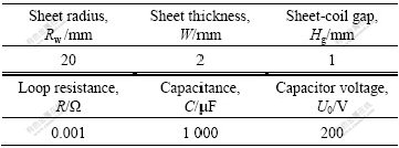
and the electromagnetic force can be calculated while the capacitance, the voltage of capacitor, the loop resistance and the geometric parameters of model are defined. The model parameters are shown in Table 1. The axial electromagnetic force is much larger than radial electro- magnetic force, and then the axial electromagnetic force density is analyzed[12].

Fig.1 Electro-magnetic finite element model of coil with core
Table 1 Parameters of FE model
2.2 Single-turn coil
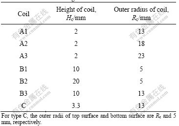
The dimensions of coil are as small as possible on account of the fixed weldment condition and the position of applied electromagnetic force. So, single-turn coil is taken into account. The electromagnetic force for single-turn coil with different section shapes is analyzed, such as long coil (type A), flat coil (type B) and coil with wedge (type C), as shown in Fig.2. Areas of all coils are equal to each other and their inner radius is 3 mm. The other parameters are shown in Table 2.
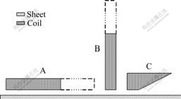
Fig.2 Different section shapes of single-turn coils (A―Long coil; B―Flat coil; C―Coil with wedge)
2.3 Multiple-turn coil
The inductance of coil is affected by geometric parameters and turn number of coil. Thereby, the electromagnetic force is also affected by them. While the
Table 2 Parameters of single-turn coil
section area of coil is invariable, the turn number of coil and the section of the wire must change synchronously. In simulation, the change of turn number of coil is implemented by changing the fill factor of coil. The maximal fill factor can be calculated from Eq.(1) while the section of wire is a rectangle[13]:
ff≤ (1)
(1)
where n is the turn number of coil; A is the section area of coil; and m is the thickness of insulating part. The maximal fill factor is shown in Table 3 while m is 0.05 mm, the height of section of coil is 10 mm and the radial dimension of section of coil is 2 mm. 0.001 Ω and 0.1 Ω are chosen as the loop resistances in circuit successively.
Table 3 Maximal fill factor with different turns

2.4 Coil with magnetic core
Except for single-turn coil, the coil with magnetic core is taken into account to concentrate the electromagnetic energy. The chosen core must have high permeability, rapid respond to varying magnetic field and low dissipation[14]. Therefore, the soft magnetic material is commended. The silicon steel, permalloy and ultracrystalline as core materials are analyzed. Their B―H curve is shown in Fig.3[15]. The core is located in coil. There is a gap between coil winding and core, as shown in Fig.1. The parameters of finite element model are listed in Table 4.
3 Results and discussion
3.1 Single-turn coil
The distribution of electromagnetic force density for single-turn coil with different sections is shown in Fig.4.
Table 4 Parameters of FE model of coil with core
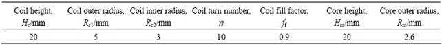
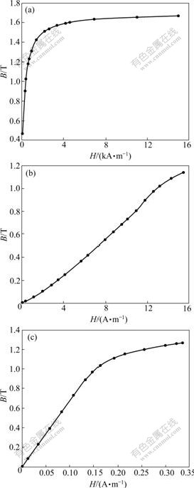
Fig.3 B―H curves of magnetic core materials: (a) Silicon steel; (b) Permalloy; (c) Ultracrystalline
The distribution of eddy current in single-turn coil is taken into account in simulation. It is shown that the maximal electromagnetic force density fy, max in sheet appears in the position near the inner radius of single-turn coil. The position is independent of the section shape of coil. The phenomena can be explained by the fact that the eddy current density in sheet and coil in the position near the inner radius of coil is larger than that in the other positions. fy, max for the flat coil is larger than that for the long coil or the coil with wedge shape section. This also correlates with the distribution of eddy current of coil and sheet.
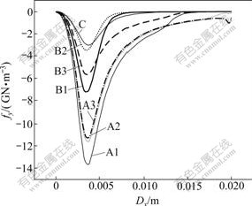
Fig.4 Distributions of electromagnetic force density for single-turn coil
3.2 Multiple-turn coil
The distribution of electromagnetic force density for multiple-turn coil is shown in Fig.5. It can be seen that the electromagnetic force decreases with increasing turns of coil while the loop resistance is small. The electromagnetic force increases with increasing turns of coil while the loop resistance is large. The characteristic of distribution of electromagnetic force doesn’t vary with varying turns of coil. The electromagnetic force under 0.001 Ω is much larger than that under 0.1 Ω. While the loop resistance is smaller, the dissipation of energy on the loop resistor is smaller, and a majority of energy translates into the magnetic energy of coil. The inductance of coil increases with increasing turns of coil. Therewith, the value and variation rate of the discharging current decrease, which causes the electromagnetic force to decrease. While the loop resistance is larger, and the dissipation of energy on the loop resistor is larger, the energy translating into the magnetic energy of coil decreases. The value and variation rate of the discharging current decrease with increasing turns of coil, which causes the dissipation of energy on the loop resistor to decrease. Therefore, the electromagnetic force increases.

Fig.5 Distributions of electromagnetic force density for multiple-turns coils under different loop resistances: (a) 0.001 Ω; (b) 0.1 Ω
3.3 Coil with core
The distribution of electromagnetic force density fy for the coil with magnetic core of different materials is shown in Fig.6. It is shown that the electromagnetic force density slightly increases while the core is located in the coil. This attributes to the increased inductance of coil, which causes the magnetic energy stored in coil to increase. Otherwise, the magnetic flux is more concentrative for the coil with core, and then the magnetic flux density increases. The simulation results show that fy for coil with silicon steel core is larger than that for coil with permalloy core which is almost equal to that for coil with ultracrystalline core. In fact, the permeability of ultracrystalline is larger than that of permalloy and silicon steel, and the saturating magnetic flux of ultracrystalline is almost equal to that of permalloy which is smaller than that of silicon steel. It is shown that the magnitude of fy lies on the saturating magnetic flux and not the permeability of core. This indicates that the core material is easy to fall in the
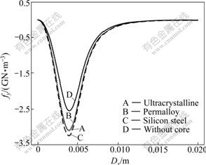
Fig.6 Distributions of electromagnetic force density for coils with different material cores
saturating magnetic situation under the large impulse exciting current. The magnitude of fy is limited by the saturating magnetic flux of the core.
4 Conclusions
1) The maximum electromagnetic force density fy, max in sheet appears in the position near the inner radius of single-turn coil. The position is independent of the section shape of coil. fy, max for flat coil is larger than that for long coil or coil with wedge shape section.
2) The effect of the turn number of multiple-turn coil on fy is dependent on the loop resistance in circuit. The kind of coil with more turns and larger inductance is commended while there is the larger loop resistance in circuit.
3) fy increases in a certain magnitude while core is located in coil. However, the magnitude of fy is limited by saturating the magnetic flux of the core.
References
[1] TIAN Xi-tang. Weld structure [M]. Beijing: China Machine Press, 1982: 14-18. (in Chinese)
[2] FAN Cheng-lei, FANG Hong-yuan, TAO Jun, LI Ming. Mechanism of weld with trailing impact rolling to control residual stresses and deformation and hot cracking [J]. Journal of Tsinghua University, 2005, 45(2): 159-162. (in Chinese)
[3] GUO S Q, LI X H, XU W L, TIAN X T. Welding distortion control of thin aluminum alloy plate by static thermal tensioning [J]. Journal of Material Science & Technology, 2001, 17(1): 163-164.
[4] LIU W, TIAN X, ZHANG X. Preventing weld hot cracking by synchronous rolling during welding [J]. Welding Journal, 1996, 79(9): 297s-304s.
[5] FAN Cheng-lei. Control of welding stress distortion and joint quality of aluminium alloy by trailing impact rolling during welding [D]. Harbin: Harbin Institute of Technology, 2005: 20-102. (in Chinese)
[6] XU Wei, LIU Xue-song, FANG Hong-yuan, XU Wen-li, YANG Jian-guo. Analysis of feasibility of controlling welding residual stress and distortion with tailing electromagnetic force [J]. Transactions of the China Welding Institution, 2008, 29(8): 65-68. (in Chinese)
[7] XU W, FANG H Y, YANG J G, XU D, XU W L. New technique to control welding hot cracking with trailing impactive electromagnetic force [J]. Mater Sci Eng A, 2008, 488(1/2): 39-44.
[8] XU Da, XU Wei, XU Wen-li, FANG Hong-yuan. Investigation and application of pulse electromagnetic force generator for trailing control of welding stress [J]. Transactions of the China Welding Institution, 2008, 29(1): 9-12. (in Chinese)
[9] XU W, FANG H Y, XU D, XU W L, LIU X S, YANG J G. Controlling welding hot cracking based on electromagnetic force [J]. Science and Technology of Welding and Joining, 2007, 12(7): 659-663.
[10] OUYANG Wei, HUANG Shang-yu. Investigation and application on electromagnetic forming technology [J]. Journal of Plasticity Engineering, 2005, 12(3): 35-41. (in Chinese)
[11] JIANG Hong-wei, LI Cun-feng, ZHAO Zhi-heng, LI Zhong, YU Hai-ping. Current research situation of electromagnetic forming technique [J]. Materials Science and Technology, 2004, 12(3): 327-331. (in Chinese)
[12] XU Wei, LIU Xue-song, YANG Jian-guo, FANG Hong-yuan. Effect of geometrical parameters of coil on electromagnetic force in coil-sheet system [J]. Transactions of the China Welding Institution, 2008, 29(9): 39-42. (in Chinese)
[13] XU Wei. A new method of controlling welding hot crack and distortion based on electromagnetic force during welding [D]. Harbin: Harbin Institute of Technology, 2008: 127. (in Chinese)
[14] YAN Mi, PENG Xiao-ling. Magnetics base and magnetic materials [M]. Hangzhou: Zhejiang University Press, 2006: 113. (in Chinese)
[15] YANG Yu-gang. Modern magnetic technology of electric power and electron [M]. Beijing: Science Press, 2003: 117-135. (in Chinese)
(Edited by YANG Bing)
Foundation item: Project(56605011) supported by the National Natural Science Foundation of China
Corresponding author: XU Wei; Tel: +86-22-66908943; E-mail: xuwei@mail.cooec.com.cn

