Magnetization arrangement of hard magnetic phases and mechanism of magnetization and reversal magnetization of nano-composite magnets
来源期刊:中国有色金属学报(英文版)2009年第5期
论文作者:刘新才 谢忍 潘晶
文章页码:1131 - 1145
Key words:permanent magnets; arrangement of easy-magnetization-axis; hard magnetic phases; nano-composite magnets; mechanism of magnetization and reversal magnetization ; L10 FePt; ordering; coercivity; size effect
Abstract: During the process of directional solidification, laser remelting/solidification in the layer on sintered magnets, die-upsetting of cast magnets, or die-upsetting of nano-composites, the arrangements of the easy-magnetization-axes of the hard magnetic phases (Nd2Fe14B, SmCo5 or Sm2Co17 type) in their designed directions have been studied. In Fe-Pt nano-composite magnets, attempts have been taken to promote phase transformation from disordered, soft magnetic A1 to ordered, hard magnetic L10 FePt phase at reduced temperatures. The dependence of the magnetization and reversal magnetization processes on the microstructures, involving the morphology and three critical sizes of particles of the FePt nano-composite magnets, are summarized. With the decrease of the nominal thickness of the anisotropic FePt film epitaxially grown on the single crystal MgO (001) substrate, the reversal magnetization process firstly changes from full domain wall displacement to partial magnetic wall pinning related to the morphology change, where the coercive force increases abruptly. The reversal magnetization process secondly changes from magnetic wall pinning to incoherent magnetization rotation associated with the particles being below the first critical size at which multi-domain particles turn into single domain ones, where the coercive force is still increased. And the reversal magnetization mode thirdly changes from incoherent to coherent rotation referred to the second critical size, where the increase of the coercive force keeps on. However, when the particle size decreases to approach the third critical size where the particles turn into the supperparamagnetic state, the coercive force begins to decrease due to the interplay of the size effect and the incomplete ordering induced by the size effect. Meanwhile, due to the size effect, Curie temperature of the ultra-small FePt particles reduces.
基金信息:the National Basic Research Program of China
the National Natural Science Foundation of China
Science and Technology Department of Zhejiang Province, China
Zhejiang Provincial Natural Science Foundation of China
Ningbo Bureau of Science and Technology, China

LIU Xin-cai(刘新才), XIE Ren(谢 忍), PAN Jing(潘 晶)
State Key Laboratory Base of Novel Functional Materials and Preparation Science,
Faculty of Materials Science and Chemical Engineering, Ningbo University, Ningbo 315211, China
Received 23 July 2008; accepted 5 January 2009
__________________________________________________________________
Abstract: During the process of directional solidification, laser remelting/solidification in the layer on sintered magnets, die-upsetting of cast magnets, or die-upsetting of nano-composites, the arrangements of the easy-magnetization-axes of the hard magnetic phases (Nd2Fe14B, SmCo5 or Sm2Co17 type) in their designed directions have been studied. In Fe-Pt nano-composite magnets, attempts have been taken to promote phase transformation from disordered, soft magnetic A1 to ordered, hard magnetic L10 FePt phase at reduced temperatures. The dependence of the magnetization and reversal magnetization processes on the microstructures, involving the morphology and three critical sizes of particles of the FePt nano-composite magnets, are summarized. With the decrease of the nominal thickness of the anisotropic FePt film epitaxially grown on the single crystal MgO (001) substrate, the reversal magnetization process firstly changes from full domain wall displacement to partial magnetic wall pinning related to the morphology change, where the coercive force increases abruptly. The reversal magnetization process secondly changes from magnetic wall pinning to incoherent magnetization rotation associated with the particles being below the first critical size at which multi-domain particles turn into single domain ones, where the coercive force is still increased. And the reversal magnetization mode thirdly changes from incoherent to coherent rotation referred to the second critical size, where the increase of the coercive force keeps on. However, when the particle size decreases to approach the third critical size where the particles turn into the supperparamagnetic state, the coercive force begins to decrease due to the interplay of the size effect and the incomplete ordering induced by the size effect. Meanwhile, due to the size effect, Curie temperature of the ultra-small FePt particles reduces.
Key words: permanent magnets; arrangement of easy-magnetization-axis; hard magnetic phases; nano-composite magnets; mechanism of magnetization and reversal magnetization ; L10 FePt; ordering; coercivity; size effect
__________________________________________________________________
1 Introduction
Until 2003, researches on nano-composite magnets have made little progress, such as their energy products for more than a decade still being 159-199 kJ/m3, lower than one fifth of the theoretic value of about 1 MJ/m3 of Nd-Fe-B nano-composite magnets[1-2]. One of the reasons lies in the fact that the magnetization arrangement of the hard magnetic phases has not been aligned. The studies in Refs.[2-5] indicate that the arrangement of the easy magnetization axis [001] of RE2Fe14B is the key issue in improving the magnetic properties of the nano-composite magnets. With the advancement in the arrangement, their energy product has reached 437.8 kJ/m3[3]. But their coercive forces are relatively low due to the decay of coercivity during hot-working process[2-6]. The mechanisms of the magnetization process and reversal magnetization process of the nano-composite magnets are distinctly different from those of the magnets with grains in micron size[7]. Thus, it is essential to explore the effects of microstructures, mainly the morphology and particle sizes, on the magnetization and reversal magnetization process which should directly associate with the coercive force of nano-composite magnets.
In this work, two key topics are mainly reviewed. One is the arrangement of the easy magnetization axes of hard magnetic phases during new synthesis routs, although some of them are in micron size. And the other is the mechanism of the magnetization and reversal magnetization of nano-composite magnets by the use of FePt based thin films or nano-particles since their microstructures are more easily controlled than bulk nano-composite magnets, in the expectation of improving the magnetic properties of nano-composites, such as Nd2Fe14B/α-Fe, Nd2Fe14B/Fe3B, Sm2Co17/Co, and Sm1Co5/Co.
2 Easy-magnetization-axis arrangement of Sm2Co17, Sm1Co5 and RE2Fe14B
In order to fully make use of the high saturation magnetizations of rare earth transition metal compounds, such as Sm1Co5, Sm2Co17 and Nd2Fe14B, and to obtain high magnetic properties, it is necessary to prepare bulk magnets with the arrangement of the easy magnetization axes of the hard magnetic phases in the whole samples in one designed direction during a certain new synthesis process, such as directional solidification, laser remelting/solidification, cast/die-upset, and hot-pressing/ die-upset.
2.1 Directional solidification of Sm-Co alloys
In the Sm-La-Co-Cu-Fe-Zr system with potentially high magnetic properties, the microstructures of directionally solidified rods are shown in Fig.1. The matrix is (Sm,La)2(Co,Fe,Cu,Zr)17; the other magnetic phase is (Sm,La)1(Co,Cu,Fe)5; and the dendrites are composed of cobalt phase[8-11]. When the crystal growth velocity is decreased from 21 to 7 mm/min, or the ratio G/R (G is the temperature gradient at the solid/liquid interface, and R is the crystal growth rate) is increased, the arrangements of the morphology of these three kinds of phases are changed from about 45? (Fig.1(a)) to 0? (Fig.1(c)) (the angle between the solidification direction and the axes of the dendrites). Although the columns of the hard magnetic phases and the cobalt dendrites are all parallel to the solidification direction (seen in Figs.1(b) and (c)), the magnetic domain walls are not always consistent with the solidification morphology (Fig.1(b)). The typical magnetic domain walls on the magnetic phases are of about 20? with the constrained solidification direction, or the rod axis. The magnetization arrangement angle, α, is defined as the angle between the constrained solidification direction and the macroscopic magnetization axis of whole sample. As seen in Fig.1(d), there are maze-like domains on the longitudinal section, and α is equal to 90?. The alloy compositions of the sample in Fig.1(d) are different from those in Figs.1(a), 1(b) and 1(c).
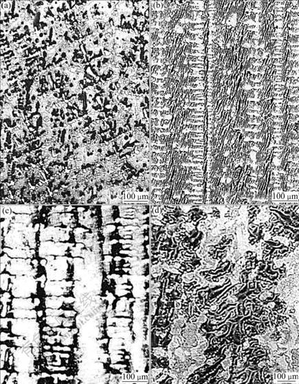
Fig.1 Typical microstructures of Sm-La-Co-Cu-Fe-Zr system directionally solidified at different crystal growth rates on longitudinal section[11]: (a) 21 mm/min; (b) 15 mm/min; (c) 7 mm/min; (d) Maze-like domains
If the angle α of a sample is about 20?-90?, the statistics results show that the remanence is 0.09-0.37 T, which is too low to have any practical use. But the samples with α of 0?-5?, directly synthesized by the directional solidification (seen in Fig.2), have very high remanence, 0.85-1.20 T, the same as the anisotropic counterpart prepared directly by the traditionally sintered method, with particles magnetized in a field above 800 kA/m.
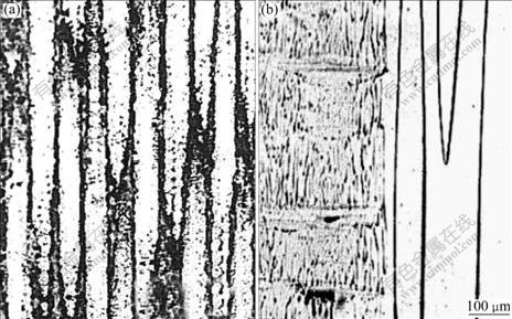
Fig.2 Microstructure (a) and magnetic domains (b) of Co-32.0Sm-3.5La-15Fe-6.5Cu-2.5Zr (mass fraction), directly synthesized by directional solidification, with the angle equal to 0?, on longitudinal section
In Sm-La-Co-Cu-Fe-Zr system, it is discovered that, whether the angle equals 0?-5? or does not depends not only on compositions but also on the G/R ratio under certain conditions. For some alloys, such as Co-32.0Sm- 3.5La-15Fe-6.5Cu-2.5Zr (mass fraction, %), if the gradient G at solid/liquid interface is 200 K/cm, the angle can be changed from 90? to 0? as the growth rate is decreased from 12 mm/min to 6 mm/min. The reason maybe lies in the fact that the ratio G/R is higher than the critical value, above which not only the morphologies of the magnetic phases but also the magnetic domains are parallel to the constrained solidification direction.
For other alloys, even both the temperature gradient and crystal growth rate are changed, α is not 0?-5? under the conditions of directional solidification temperature of 1 553-1 723 K and crystal growth rate of 0.3-25 mm/min. Only by sintering method, can their micron particles be arranged in a magnetic field and the remanences of the sintered samples be high enough as magnets. It is deduced that the atoms in these magnets occupy error points in the crystal lattice of (Sm,La)2(Co,Cu,Fe,Zr)17 or (Sm,La)1(Co,Cu,Fe)5, during the non-equilibrium directional solidification process. So, these alloys cannot be now prepared directly by the solidification process[10-11].
For the alloys with the angle equal to 0?-5?, the effects of heat treatment on magnetic properties have been studied, and these magnets, finally with 143.3 kJ/m3, directly prepared by directional solidification and heat treatment, are more ductile than the sintered ones with the same compositions.
However, the macroscopic c-axis texture orientation of Nd2Fe14B cannot be formed directly through directional solidification under the conditions of temperature gradient at the solid/liquid surface of 200-1 000 K/cm, and the crystal growth rate of 12-250 μm/s[12-13].
2.2 c-axis texture of Nd2Fe14B solidified in laser remelting/solidification layer on anisotropic magnets
Three kinds of commercial anisotropic sintered Nd15Fe77B8 magnets with their magnetization direction along X-, Y-, and Z-axis, respectively, have been cut into cube, whose dimensions are 42 mm×20 mm×8 mm. Their surfaces parallel to XOY plane, are remelted/ solidified by 5 kW Roffin-Sinar 850 type of CO2 laser, whose beam direction is in the opposite Z-axis. The above process is under argon protection. The scanning parameters, such as the power 2.5 kW, the diameter of the laser light spot 0.05 mm, and the scanning velocity 10-30 mm/s are used.
Only when the magnetization axis of the whole anisotropic magnet substrates is perpendicular to the heat flux direction of the layer, can c-axis texture be obtained in the laser melting/solidification layer. The same orientation of the c-axis texture of Nd2Fe14B in the layer can be achieved as that of the anisotropic substrates (seen in Fig.3). The plate-like magnet domain walls in the layer are parallel to those in the substrates. If the geometric relationship between the magnetization axis of the substrates and the heat flux direction of the laser melting/solidification pool is different from the above, c-axis texture cannot be formed and the laser melting/solidification layer will be isotropic[14-18].
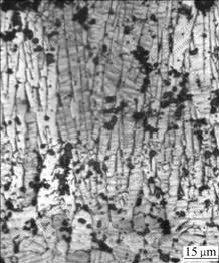
Fig.3 Magnetic domains in longitudinal section in laser melting/solidification layer on anisotropic magnet with its magnetization axis normal to heat flux direction[18]
2.3 [001] texture of cast/die-upset PrxFe93.5-xB5Cu1.5 (x=15-19)
Compared with the magnets prepared by powder sintering, the cast/die-upset process of RE-Fe-B-Cu magnets includes no powder preparing step. Thus, cast/die-upset magnets should exhibit lower oxygen content than the sintered ones[19]. However, the residual magnetization of 0.78-1.12 T,in the previous work,is much lower than that of sintered ones. Their highest intensity ratio of I006/I105 determined by X-ray diffraction is merely 0.76, indicating that the easy magnetization axes of Pr2Fe14B grains are poorly aligned[20].
The cast slabs are first cut into small pieces for die-upset. Die-upset is carried out at 973-1 273 K with strain rate of 10-6-100 s-1, and strain of 0-80%[21].
When die-upset parameters are under the conditions of temperature 973-1 173 K, strain rate 10-3 s-1 and strain 80%, the magnetic domain walls (seen in Fig.4) on the longitudinal plane are parallel to the die-upset direction. And the intensity of I006 of the die-upset PrxFe93.5-xB5Cu1.5 is the highest on the diffraction pattern. The residual magnetization of these magnets has reached 1.3 T[21]. It is confirmed that die-upset is in favor of obtaining the anisotropic RE2Fe14B bulk magnets.
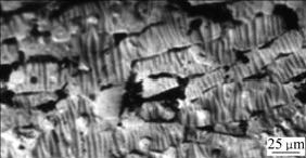
Fig.4 Magnetic domains of cast PrxFe93.5-xB5Cu1.5 die-upset at 973-1 173K, strain rate of 10-3 s-1 and strain of 80%, on longitudinal section[21]
3 Hot-pressed and die-upset Nd-Fe-B nano- composite bulk magnets
3.1 Arrangement of Nd2Fe14B phase along [001]
It is necessary to note that the die-upset process in the hot-pressing/die-upset method is different from that in the above cast/die-upset method. Only when its heating rate is much larger than that of the latter, and its die-upset duration at high temperature is much shorter than that of the latter, can the [001] texture be achieved in Nd-Fe-B nano-composite bulk magnets, and can their energy products much higher than 159.2-199 kJ/m3, be reached.
In Fig.5[5], it is observed from the XRD diffraction pattern, hot-pressed Nd12Dy2Fe73.2Co6.6Ga0.6B5.6 alloy consists of randomly oriented Nd2Fe14B grains with homogeneous distribution in the grain size of 50-100 nm, whose (006) and (008) peaks are inconspicuous while (314), (410) and (214) appear as the main reflection planes, somewhat similar to the XRD pattern of the same composition powders, indicating that the hot-pressed magnet has isotropic property. While the microstructures of the die-upset alloy(seen in Fig.5(b)) show that the Nd2Fe14B grains in the shape of platelet with 50-100 nm in thickness and 200-500 nm in length are well aligned perpendicular to the press direction. Its XRD pattern shows that (006) peak becomes the dominant reflection, (004) and (008) peaks are obvious(shown in Fig.5(a)), indicating the formation of magnetic texture by the alignment of the easy-magnetization-axis of tetragonal unit cell of the Nd2Fe14B phase after the hot-pressing/ die-upset process.
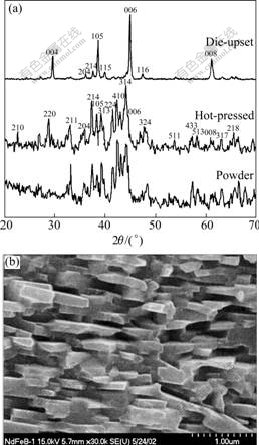
Fig.5 XRD patterns of powder, hot-pressed and die-upset Nd12Dy2Fe73.2Co6.6Ga0.6B5.6 alloy (a) and microstructures after die-upset on section parallel to press direction (b) [5]
3.2 Influence of die-upset parameters on magnetic properties
As seen in Fig.6[4], with the increase of deformation strain, the values of Br and (BH)max of the Nd13.6Fe73.7-Co6.6Ga0.6B5.5 alloy increase monotonously, but Hc decreases. Moreover, the loop becomes more square, which is beneficial to achieving high (BH)max. However, when the deformation strain is in excess of 65%, the magnetic properties will decay considerably, resulting from the crack present in the magnets[4].
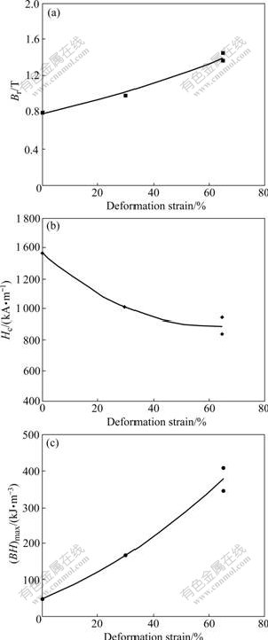
Fig.6 Effects of deformation strain on magnetic properties of single alloy Nd13.6Fe73.7Co6.6Ga0.6B5.5[4]
Br, Hc and (BH)max reach their maximum values simultaneously after die-upset at 1 023 K in addition to the best squareness of loops, indicating that 1 023 K is the optimal temperature for the hot-working of Nd13.6Fe73.7Co6.6Ga0.6B5.5 alloy. While die-upset temperature 1 273 K is so high that it will lead to excessive grain growing and coalescing, which results in the decay of Br and substantial decline of Hc[4].
Br is 1.2 T for the magnet die-upset of 873 K where the Nd-rich grain boundary is not in liquid state, indicating that the magnet with certain anisotropy can be obtained even without the grain boundary in liquid state during die-upset process. This phenomenon is worthy of studying further.
3.3 Effects of Nd content on magnetic properties
Fig.7 shows the effects of Nd content in NdxFe94-xB6 on the magnetic properties of powder, hot-pressed magnet and die-upset one[6]. With the Nd content decreasing, a relatively high Br of the NdxFe94-xB6 die-upset magnet is obtained to be about 1.2 T, for 12%-18% (molar fraction) Nd; then it steeply decreases for 10%-12% Nd; however, it increases to 0.8-1.0 T for 6%-10% Nd. From these results, Br is lower than 1.0 T for x(Nd)<11%. Although this Nd-lean alloy consists of Nd2Fe14B and α-Fe phase, it is difficult to induce texture in this kind of magnet[6].
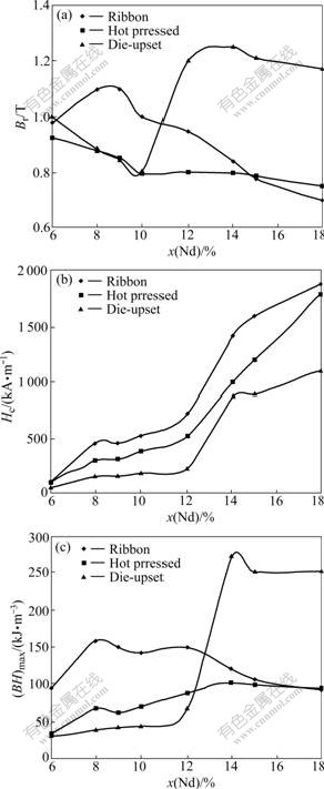
Fig.7 Effects of Nd content on magnetic properties of powder (a), hot-pressed (b) and die-upset magnet (c) [6]
Hc of the die-upset NdxFe94-xB6 magnet decreases monotonously with the decrease of the Nd content. The decrease is slow for 14%-18% and 6%-12% Nd, but substantial for 12%-14% Nd (molar fraction).
(BH)max of the die-upset NdxFe94-xB6 magnet varies slightly for x(Nd)≥14%, and keeps a value of about 250 kJ/m3 with the decrease of Nd content. It decreases drastically for 12%-14% Nd, and with further decrease of Nd content, (BH)max keeps constant.
Being prepared by the hybrid method (blending the powders of RE-rich Nd-Fe-B alloy and RE-lean one, even of both RE-rich alloy and soft-magnets without any RE content, then hot-pressing and die-upset), energy product of Nd2Fe14B based nano-composite magnets have reached 437.8 kJ/m3[3].
With discussion above, anisotropy in the Nd2Fe14B nano-composite magnets could be induced by both the hot-pressing and die-upset process, accompanying with the increase of remanence and energy product but the decay of coercivity, which prevent the further improvement of energy product after annealing. The reversal magnetization and coercivity mechanism of bulk nano-composite magnets certainly depend on the microstructure details, such as the three-dimensional spatial distribution of the phases, and grain size. Thus, it is essential to establish the relationship between the microstructure and coercivity clearly. However, up to now, the coercivity mechanism of nano-composite magnets, Nd2Fe14B/α-Fe or Nd2Fe14B/Fe3B, has not been developed. So in this work, the mechanism of FePt-based nano-composite magnets is reviewed.
4 Ordering transformation and coercivity mechanism of FePt-based nano-composite magnets
The FePt thin films with easily controllable and reproducible microstructures are comfortable to be applied in the field of coercivity study. Especially, thin-film growth allows the control of layer thickness, and it can also provide a means for crystallographic alignment of the easy magnetization axis of the hard phase. An additional advantage of the FePt thin films is to allow a realistic estimation of the ultimate gain in performance that may potentially be realized in exchange-coupling bulk magnets. The coercivity study of FePt based nano-composite magnets is expected to guide the efforts on the enhancement of the magnetic properties of other kinds of nano-composite magnets with much lower material cost, such as Nd2Fe14B/α-Fe, Nd2Fe14B/ Fe3B, Sm2Co17/Co, and Sm1Co5/Co.
L10 FePt alloy has attracted much attention for decades due to its remarkable uniaxial magnetocrystalline anisotropy (Ku≈7×10⁶ J/m3) along the c-axis direction[22-23], which leads to good intrinsic coercive forces with x=0.50-0.68 in FexPt1-x (seen in Fig.8)[24], chemical stability, high Curie temperature (Tc>723 K)[24], and attractive saturation magnetization (4πMs=1.38 T[23]) in dense bulk form. In recent years, thin films or particles of L10 FePt are expected to be applied in the synthesis of ultrahigh density magnetic recording media and micro-electro-mechanical systems (MEMS). According to KNELLER and HAWIG[25], hard phase and soft phase will be well coupled with each other when the size of the soft phase is within the critical one bcs (bcs=![]() =10 nm for L10 FePt, where A is exchange stiff constant), resulting in a very high energy product of about 716.4 kJ/m3 in theory for the FePt/Fe nano-composite magnets[26].
=10 nm for L10 FePt, where A is exchange stiff constant), resulting in a very high energy product of about 716.4 kJ/m3 in theory for the FePt/Fe nano-composite magnets[26].
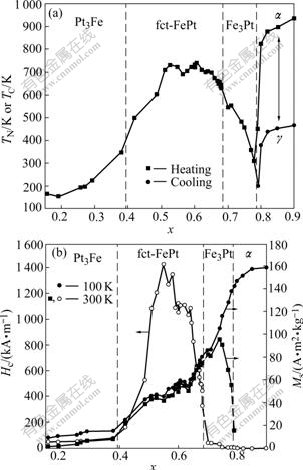
Fig.8 TN or TC during heating and cooling (a), Ms and Hc at different temperatures (b) as function of x in FexPt1-x nanoparticles[24]
In this work, the ordering transformation is firstly discussed for there are both soft and hard magnetic phases after ordering transformation.
4.1 Promoting ordering transformation at reduced temperature
The equi-atomic FePt compounds have two kinds of crystal structural phases: one is A1 or fcc, which is chemically disordered and exhibits soft magnetic behavior; and the other is L10 or fct, which is chemically ordered and magnetically hard. Since room-temperature as-synthesized FePt materials take the A1 structure, heat-treatment (usually above 773 K) is required to convert the disordered A1 to the ordered L10. Excessive grain growth that is deleterious to coercivity easily takes place at elevated temperature, thus, it is desirable to find a way to produce L10 FePt phase at reduced temperatures.
4.1.1 Ordering kinetics
The A1→L10 transformation is induced by the nucleation and growth of the ordered phase in the disordered matrix; and both are thermally activated processes[27]. The activation energy for nucleation(En) and growth(Eg) could be expressed respectively as
![]() (1)
(1)
![]() (2)
(2)
where kB is the Boltzman’s constant; T is the annealing temperature; Rn is the nucleation rate; tE is the saturation time constant; Rn0 and tE0 are constants; En=[(0.5-0.6) ±0.1] eV and Eg=(0.9±0.1) eV are estimated, respectively, according to experimental results[28]. En is lower than Eg, resulting in an easy nucleation process for the L10 ordered domains in the FePt thin films, and a difficult growth process at high ordering temperature. The activation energy for growth can be compared to that for atomic diffusion in disordered FePt matrix, thus, it is suggested that the growth of the L10 ordered domains is determined by atom diffusion[28].
Based on this understanding, the addition of the third element, introduction of defects in films or between the films and buffer layers, using off-stoichiometric method, transformation under high pressure, processing in external magnetic field and with different kinds of sputtering gas could be effective to be applied to lowering down the ordering temperature.
4.1.2 Adding the third element
It could be found in Fig.9 that the ordering beginning temperatures where coercivity begins to steeply increase, resulting from the formation of L10 phase with large Ku, are 598, 623 and 673 K for chemically-synthesized (FePt)85Au15, (FePt)88Ag12, and Fe48Pt52 nano-particles, respectively[29]. And the ordering temperatures are 823, 873 and 873 K, respectively, for (Fe0.588Pt0.412)85Pd15, (FePt)90Cr10 and (Fe0.412Pt0.588)85Cu15 nano-particles. The increase of the coercivity of Fe48Pt52 particles is the slowest, whose slope of Hc―T curve is parallel to that of (Fe0.412Pt0.588)85Cu15. Compared with Fe48Pt52, additive Au and Ag decrease the ordering temperature by 75 K and 50 K, respectively; while additive Pd, Cr and Cu increase the ordering temperature by 150 K, 200 K and 200 K. For (FePt)85B15 film in thickness of 10 nm, the coercivity increases drastically above 673 K, while it takes place at about 873 K for the pure FePt film[23].
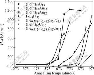
Fig.9 Relationship between annealing temperature and coercivity of (Fe, Pt)-M (M=Au, Ag, Pd, Cr, Cu, B) chemically-synthesized nano-particles and (FePt)85B15 film with 10 nm in thickness[29-31]
Decrease of the activation energy, i.e. ordering temperature, for Ag and Au-doped Fe-Pt nano-particles is attributed to the segregation of Ag and Au atoms from A1 FePt to form Ag and Au phases during the heat treatment, leaving the increased number of vacancies, then resulting in the increase of the diffusion coefficient of Fe and Pt atoms[30]. Somewhat similarily, decreasing of the ordering beginning temperature by boron addition is attributed to the high diffusivities of Fe and Pt due to the defects created by the movement of the boron atoms to interstitial or substitutional lattice sites[29]. Thus, it can be concluded that reduced ordering temperature could be obtained by adding the third element which yields the defects to be beneficial to the diffusivities of Fe and Pt atoms.
4.1.3 Defects
It is well agreed that defects play an important role in the A1→L10 transformation. Defects or internal stress may contribute to the formation of the crystalline nucleus, the grain boundaries and dislocations acting as diffusion tunnels[32]. And the addition energy, stored in the form of a variety of defects including grain boundaries, dislocations, internal strain or stress, will be released during annealing process, which is found to shorten the ordering transformation time and/or lower the ordering temperature of L10 alloys[33]. Fig.10 shows that the value of S0, namely, the volume fraction of L10 CoPt phase which is used to describe the degree of ordering, is retarded by 0.1-0.25 for the preannealed films compared with the un-treated ones. This is interpreted to result from the phenomenon that the preannealing treatment eliminates mostly dislocations or vacancies.
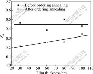
Fig.10 Influence of film thickness on S0 (volume fraction of L10 CoPt phase) with or without preannealing at 523 K for 80 min before ordering annealing at 973 K for 10 min[34]
4.1.4 Off-stoichiometric alloys
As shown in Fig.11, the size of L10 crystal cell, a, holds a constant for x≤38 in FexPt100-x films, then decreases monotonically when x>38. On the other hand, the value of c decreases monotonically when x≤38, considering that Fe sites in the L10 structure are partly replaced by Pt atoms[35]. It is worth noting that the degree of atomic ordering of the L10 FePt phase, quantitatively described by S= 0.85[I001/I002]1/2[36], is benefited from the decrease of c/a and reaches a maximum (0.6±0.1) around x=38 in FexPt100-x films grown at just 573 K where the value of c/a reaches the minimum (0.955). It is expected that the effect of strain, resulting from the tetragonal c/a, is dominant in this course although the mechanism is not clearly understood now.
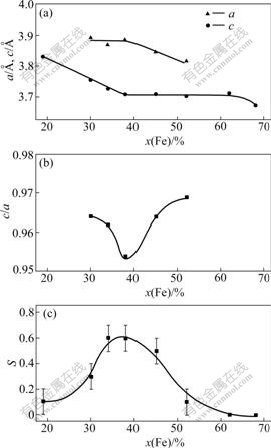
Fig.11 Variation of lattice constants of c and a (a), tetragonal c/a (b) and S (c) with x in FexPt100-x films epitaxially grown on Pt buffer layers at 573 K[35]
4.1.5 Lattice mismatch ?a/a between FexPt1-x films and buffer layers
In Fig.12, it is found that S increases monotonically for Fe38Pt62 films with ?a/a increasing, and reaches the maximum value of 0.8±0.1 at ?a/a=9.0%. On the other hand, for Fe52Pt48 films, when ?a/a<5.4, S increases drastically and achieves the maximum value of 0.7±0.1 at ?a/a=6.9%. However, when ?a/a=9.7%, S decreases to 0.6±0.1. The high value of S obtained at low temperature of 573 K is attributed to an excessive number of misfit dislocations, resulting from the lattice mismatches between the FexPt100-x films and buffer layers, which are expected to promote the atomic diffusion. However, too large lattice mismatch leads to the decrease of S for the Fe52Pt48 films[37].
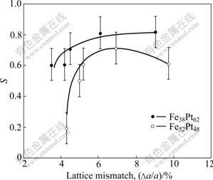
Fig.12 Degree of chemical ordering of Fe38Pt62 and Fe52Pt48 films expitaxially grown on buffer layers at 573 K as function of lattice mismatch between films and buffer layer, ?a/a, realized by changing materials of buffer layer[37]
4.1.6 High pressure
Fig.13 shows the effect of annealing temperature on S of the powders and bulk samples fabricated by warm compressing the initial powders under high pressure[38]. It is obvious that for the compacted samples, S is of the order of zero before annealing temperature reaches 573 K, while it jumps to 0.9 at 673 K, indicating that A1→L10 transformation is almost accomplished. However, for the powder samples, 773 K is required to fulfill the ordering transformation. The high pressure is apparently responsible for the 100 K shift of the ordering temperature by compressing the fcc structure in the direction of c axis to expedite the formation of the tetragonal one, L10.
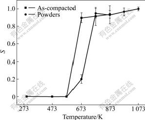
Fig.13 Dependence of S on annealing temperature for bulk samples with or without pressure of 3.8 GPa annealed for 10 min[38]
4.1.7 External magnetic field
It is shown in Fig.14(a) that under the magnetic field of 1.03×10⁵ A/m, the (001) and (110) superlattice peaks corresponding to the L10 phase for the FePt films, deposited on the Co25Ag75 underlayer, could be observed after annealing at 673 K; while without the magnetic field those typical peaks could no longer be observed until increasing the annealing temperature up to 773 K, indicating that the external magnetic field can induce the ordering of FePt films at reduced temperature.
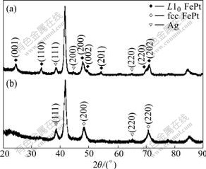
Fig.14 XRD patterns of FePt films grown on Co25Ag75 underlayer annealed at 673 K for 30 min with (a) and without (b) external magnetic field[27]
4.1.8 Sputtering gas
It is exhibited in Fig.15 that the intensity ratio I001/I111 is utilized to describe the ordering, because the (001) peak corresponds to L10 phase, and (111) peak corresponds to A1 phase. I001/I111 for Kr-sputtering gas develops from lower temperature of 523 K, while it develops from 573 K for Ne and 623 K for Ar. Meanwhile, I001/I111 at 673 K for Kr is 4.5, also distinctly higher than 0.55 and 0.75 for Ne and Ar, respectively. The reduced ordering temperature in the FePt films by the use of Kr as sputtering gas is interpreted to result from the fact that the Kr atoms possess the highest average kinetic energy, since the atomic mass of Kr is twice or four times heavier than that of Ar or Ne, respectively. Thus, the Kr sputtering gas can promote the ordering transformation[39].
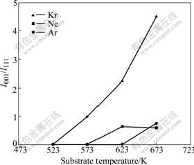
Fig.15 Variation of intensity ratio of I001/I111 for films deposited by sputtering gas Ne, Ar and Kr with different substrate temperature[39]
With discussion above, we can conclude that the decrease of the ordering temperature is finally originated from the promotion of the atomic diffusion no matter what technical methods are employed.
4.2 Mechanism of magnetization and reversal magnetization of FePt based nano-composite films or particles
4.2.1 Effects of microstructure on coercivity of films or particles
Fig.16 exhibits the TEM images of the perfectly aligned (001) FePt films, epitaxially grown on the MgO (001) single crystal substrate at high temperature of ≥973 K which is employed to ensure the high ordering of the films, for different nominal thickness, tN[40-41].

Fig.16 TEM images of perfectly aligned FePt (001) films epitaxially grown on MgO (001) single crystal substrate at ≥973 K, for different nominal thickness, tN: (a) 60 nm; (b) 50 nm; (c) 45 nm; (d) 20 nm; (e) 5 nm; (f) 3 nm; (g) 1 nm[40-41]
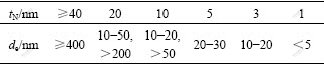
It is observed in Fig.16 that interconnected network structures with voids in the shape of strip are observed for tN=60 nm (Fig.16(a)). The voids expand with tN decreasing, and eventually some isolated particles emerge when tN=50 nm (Fig.16(b)). It is notable that a remarkable change of the film takes place in the morphology from continuous network (Fig.16(b)) for tN=50 nm to maze-like isolated particle for tN=45 nm (Fig.16(c)). The size distribution of the particles is bimodal for the 20 nm-thick film (Fig.16(d)), consisting of larger particles with a typical size de>200 nm and smaller ones in the size range from 10 to 50 nm. From experimental observation, the particle shapes are flat ellipsoids. On this situation, ah<al≈as, where al, as, ah are the half lengths of long axial, short axial and height of the ellipsoid, respectively. The size of the ellipsoidal particles de is equal to 2al. And in Fig.16(e) and Fig.16(f), the size of particles decreases from 20-30 nm for tN=5 nm, to 10-20 nm for tN=3 nm, then decreases to <5 nm when tN=1 nm (Fig.16(g)). The whole size distribution is summarized in Table 1[23, 40-43].
Table 1 Size distribution of particles in FePt films with different thickness [23, 40-43]
It is displayed in Fig.17[40] that the initial magnetization curves, described to help analyzing the characteristic of the magnetization process, are of characteristic of domain wall displacement for the films with thickness ≥20 nm since the magnetization easily progresses at low magnetic field (Curves (a), (b), (c) and (d)), indicating that those films consist of multi-domain continuous network or isolated maze-like particles, at least, isolated particles in bimodal distribution (Fig.16(d)). When tN decreases from 18 to 15 nm (from Curve (e) to (f)), the minor part of the magnetization rotation at large magnetic field corresponding to the single domain particle is observed. With tN further decreasing to 12 and 10 nm (Curves (g) and (h)), the fraction of the magnetization under large magnetic field increases, which is ascribed to the increased volume of single domain particles. Finally, the initial magnetization curves are of characteristic of magnetization rotation for tN≤8 nm (Curves (i), (j) and (k)), indicating that these films are merely composed of single domain particles.
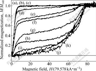
Fig.17 Initial magnetization curves measured at 4.5 K perpendicular to film plane of FePt films epitaxially grown on MgO (001) for different thickness: (a) 40 nm; (b) 30 nm; (c) 25 nm; (d) 20 nm; (e) 18 nm; (f) 15 nm; (g) 12 nm; (h) 10 nm; (i) 8 nm; (j) 5 nm; (k) 3 nm[40]
It is shown in Fig.18[40, 42] that Hc increases appreciably with tN decreasing and holds a very low value when 50 nm≤tN≤100 nm. However, Hc of 159.2 kA/m for tN=50 nm jumps to 2 228.8 kA/m for tN=45 nm, measured under a magnetic field of 5.5 T, with the morphology changing from continuous maze to particulate. A quite large Hc value of about 3 422.8 kA/m for tN =40 nm, measured under a magnetic field of 14 T, is achieved in spite of the fact that the domain wall displacement is dominant in magnetization process of the film. Measured under 14 T, Hc increases with the decrease of tN when 5 nm≤tN<40 nm; Hc reaches the maximum value of 5 572 kA/m for tN =5 nm; then begins to decrease when tN<5 nm; but still keeps a large value of 5 094.4 kA/m for tN =3 nm; at last, it sharply decreases to 1 432.8 kA/m for the film with tN=1 nm and de<5 nm.
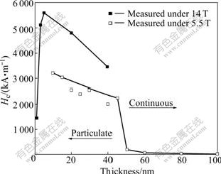
Fig.18 Effect of film thickness epitaxially grown on MgO (001) single crystal substrate at 973 K, on Hc, measured perpendicular to film plane under maximum magnetic field of 14 T at 295 K for 1 nm≤tN≤40 nm and 5.5 T for 10 nm≤tN≤100 nm[40-42]
Since the L10 ordered FePt phase possesses large uniaxial Ku, in theory, it could be expected a huge Hc value of 9 552 kA/m deduced from the coherent rotation model[41] (2Ku/Ms≈9 552 kA/m) for ideally single domain L10 FePt particles. In practice, huge coercivity as high as 8 358 kA/m has achieved at 4.5 K for the film of tN=5 nm. This value is very approaching to the expected one.
4.2.2 Domain wall pinning sites
It is remarkable that Hc suddenly increases from 159.2 kA/m for tN=50 nm to 2 228.8 kA/m for tN=45 nm (Fig.18), with the morphology changing from continuous to particulate, resulting in the magnetic domain walls movement changing from full displacement to partial domain wall pinning due to the existence of void boundaries as domain wall pinning sites. However, no sharp increase is observed for the films deposited on SiO2 substrate, although their morphology changes are the same as those of the films deposited on MgO (001) single crystal. Considering that the continuous polycrystalline films deposited on SiO2 polycrystalline substrate have real grain boundaries, a high Hc of >1 034.8 kA/m is obtained in those kinds of continuous films due to strong domain wall pinning by the grain boundaries as well as by the twins within the grains, both of which are absent in the single crystalline films deposited on MgO (001) single crystal substrate[42]. K?NDIG et al[44] have shown that a large Hc of about 1 592 kA/m at the expense of magnetization can be obtained in melt-spun ribbons of a ternary Fe35Pt35P30 eutectic composition by grain refinement as well as by introducing PtP2 non-magnetic particles as possible pinning sites.
4.2.3 Critical size for single domain particle
The domain structure of L10 FePt particles changes from multi-domain to single domain when de is below the critical size Dc1, approximately estimated[23] by using the following equation:
![]() (3)
(3)
where Ain=ASsp2/a, is an intrinsic constant, Ssp is the spin quantum number, and N⊥ is the demagnetization factor along the height of the ellipsoid, given by[23]
![]() (4)
(4)
k=ah/al, 0<k<1. By assuming 2ah=tN, 2al=2as=de, k, N⊥ and Dc1 are estimated and calculated. k, N⊥ and Dc1 are 0-0.2, 7.81-12.56, and 155-200 nm, respectively.
From the magnetic force microscopy(MFM) observation, it has been revealed that in the case of tN= 20 nm, the calculated Dc1 of 155 nm is in good agreement with the experimental result of 180 nm. The slight difference is thought to result from the fact that the actual height of most particles is larger than the nominal thickness tN[23].
The film in thickness of 40 nm is composed of particles of de>400 nm with multidomain structure. When tN decreases to 20 nm, it is comprised of two kinds of particles, the larger one about 200 nm with multidomain structure, the smaller one with single domain structure. The volume fraction of single domain particles increases with tN decreasing, leading to the increase of Hc at first when tN≤40 nm. This is mainly attributed to the change of the reversal magnetization process from magnetic wall displacement to wall pinning. With the decrease of the film thickness and the size of the particles, most of single domain particles appear in the film, accompanying with reversal magnetization model changing from wall pinning to magnetization incoherent rotation.
4.2.4 Critical size for reversal magnetization mode
However, when tN decreases from 10 to 5 nm, Hc increases (Fig.11) even these films consist of single domain particles. This is explained by the change of reversal magnetization mode. According to micromagnetic theory, reversal magnetization mode changes from incoherent to coherent rotation when the particle diameter de is below the critical diameter Dc2[41] given by where q is the geometrical factor and N∥ is the demagnetizing factor along the longitudinal axis of the ellipsoid. The Dc2 value of 38 nm is calculated for the ellipsoidal particle with 5ah=al=as, while Dc2≈20 nm is obtained from experiment[43].
![]() (5)
(5)
For tN=10 nm, the film is composed of two kinds of particles in size of 50 nm with magnetization in coherent rotation and smaller ones in the sizes below Dc2 with magnetization coherent rotation in reversal magnetization process. When tN decreases to 5 nm, it is comprised of particles of about 20-30 nm which is comparable to the value of Dc2. It is expected that the reversal magnetization mode changes from incoherent to complete coherent rotation, giving rise to the increase of Hc.
4.2.5 Critical size for superparamagnetism
Hc begins to decrease for tN<5 nm, and the film in thickness of 1 nm has a low Hc of 1 432.8 kA/m, although the magnetization of the particles, mostly smaller than 5 nm with single domain structure, is coherent rotation in reversal magnetization process. It is explained that when the particle size reduces to be close to the superparamagnetic size, thermal fluctuations and the possibility of quantum tunneling of magnetization are expected to begin to affect and dominate the magnetic behavior, which is called “size effect”.
In Fig.19, the FePt nano-particles in a carbon matrix are fabricated by depositing both FePt layers in thickness of 0.3-1 nm and carbon layers in thickness of 0.3-4.0 nm alternatively, followed by annealing at 873-1 073 K which leads to the formation of the nano-particles in carbon matrix. While the pure Fe52Pt48 nano-particles are synthesized by chemical method, considering the thermal fluctuation, CHRISTODOULIDES et al[45] have reported that the coercivity as a function of spherical particle size, d, follows the following relation:
![]() (6)
(6)
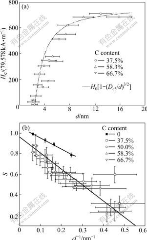
Fig.19 Variation of coercivity with grain size (a) and degree of chemical ordering as function of inverse grain size (b) for FePt nano-particles in carbon matrix as function of C content in films[46-47]
where Dc3 is the superparamagnetic size and Ha (=2Ku/Ms) is the anisotropic field.
The Hc value of <796 kA/m is relatively low (seen in Fig.19) even in the size of 10-20 nm. We believe that this is mainly attributed to the lower Ku value associated with incomplete atomic ordering since Ku is originated from the long-range ordering of alternatively stacked Fe and Pt layers along the c-axis. It is eventually affected by reduction in thickness along the c-axis to several atomic layers.
Hc decreases distinctly with decreasing particle size at d≤8 nm, then vanishes at d=2 nm (Fig.19(a)). This is partly attributed to the increasing impact of the size effect, and the effect of chemical ordering on Hc is also supposed to be taken into account. TAKAHASHI et al [48] have found that there is a size dependence in the ordering process of FePt nano-particles. Although continuous FePt thin film is L10 perfectly ordered at 773 K, FePt nano-particles with size smaller than 5 nm cannot be ordered even annealing at 873 K for 1 h. Fig.19(b) shows that S decreases with reducing particle size. The results of both RONG et al[49] and CHRISTODOULIDES et al[45] in Fig.19(b) reveal a linear relation between S and 1/d.
In theory, the minimal stable particle size, estimated from Ref.[43], is as small as 2.8 nm for L10 FePt at room temperature:
Dc3=(60 kBT/Ku)-1/3 (7)
A detailed study on the ultrasmall nano-particles reveals that S sharply drops when d is below 3 nm[44] and FePt particles are not ordered to the L10 structure when d<2 nm, namely so called superparamagnetic limit[44, 46-47]. This agrees well with the experimental results. However, it is not clear about why the linear relation takes place. Further work is required to fully understand the relation among size effect, chemical ordering and the real effect of particle size on Hc.
It is demonstrated that the coercivity is strongly associated with the characteristic size and the morphology of the assemblies of ferromagnetic particles. It is an effective way to induce a high Hc by controlling the size of the particles and by introducing domain wall pinning sites, i.e., nonmagnetic grain boundary and defects. The related studies on the relation of microstructures and coercivity are still going on.
4.2.6 Size effect on TC
Fig.20 shows the dependence of TC on the L10 FePt particle size. TC decreases with particle size declining, remarkably when d<6 nm. For nano-particles smaller than 2 nm, TC for the L10 phase cannot be generated since the phase transition cannot be realized. The shift of TC from the value for bulk materials is expressed by[50]
![]() (8)
(8)
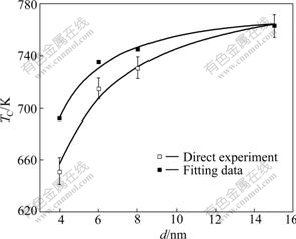
Fig.20 Size effect on TC for chemically-synthesized Fe52Pt48 nano-particles[47]
where TC(d) is the Curie temperature as a function of d, TC(∞) is the bulk Curie temperature, the value of d0 is comparable to the lattice constant, and v is the critical exponent of the correlation length.
However, the effect of chemical ordering on the TC should be considered in addition to the effect of particle size. This shows that the dependence of TC and S on fixed particle size can be described in the region of 0.6≤S≤1 by a linear expression[47]:
TC=Tcf+afS (9)
where Tcf and af are fitting parameters. It is notable that TC value in the Eq.(9) corresponds to the solid square in Fig.19(b), which is close to the real size effect on TC of fully-ordered L10 Fe52Pt48 nano-particles in Fig.20.
5 Conclusions
1) During directional solidification, the easy- magnetization-axes of hard magnetic phases of the alloys in Sm-La-Fe-Co-Cu-Zr system can be made to be parallel to the constrained solidification direction; but those of the alloys in Nd-Fe-B system cannot be done.
2) In the laser remelting/solidification layer on the surfaces of the anisotropic sintered Nd15Fe77B8 magnets, only when the magnetization directions of the substrate magnets are perpendicular to the heat flux direction in the layer on their surfaces, can the easy-magnetization- axes of Nd2Fe14B columns be parallel to the magnetization directions.
3) The texture of the easy-magnetization-axis of RE2Fe14B can be obtained in both cast/die-upset bulk PrxFe93.5-xB5Cu1.5 in micron size, and hot-pressing/ die-upset RE2Fe14B based nano-composite magnets.
4) The FePt ordering transformation from soft magnetic phase to hard magnetic one will be promoted at reduced temperature by adding the third elements (such as Au, Ag and B), introducing defects (such as dislocations or vacancies, lattice mismatch and lattice change in off-stoichiometric FePt alloys), and involving external transformation condition (high pressure, magnetic field and sputtering gas with high average kinetic energy), which are beneficial to the improvement of diffusion of Fe and Pt atoms.
5) With the nominal thickness tN of the films decreasing from 100 to 1 nm, the anisotropic FePt films epitaxially grown on MgO (001) single crystal substrate change from continuous network to particulate, resulting in the jump of the Hc, which is attributed to the reversal magnetization model changing from the magnetic wall displacement to partial wall pinning. When the diameters of the particles are below the critical size Dc1, the reversal magnetization process changes from wall pinning to incoherent rotation with the increase of Hc. And when the diameters are below Dc2, there is the transformation from incoherent to coherent rotation with the increase of Hc. When the diameter is below the supperparamagnetic size Dc3, thermal fluctuations and the possibility of quantum tunneling of magnetization are expected to begin to dominate, resulting in the fact that Hc decreases since the ordering of the particles is decreased and finally the particles cannot be ordered any more. Meanwhile, the size effect reduces the Curie temperature of FePt particles.
References
[1] SKOMAKI R, COEY J M. Giant energy product in nanostructured two-phase magnets [J]. Phy Rev B, 1993, 48: 15812-15816.
[2] GUO Peng-ju, LIU Xin-cai, PAN Jing, LI Yong, CUI Ping. Recent progress of nonaocomposite magnet by die-upset [J]. Rare Metal Materials and Engineering, 2008, 37(3): 377-381. (in Chinese)
[3] LIU S, HIGGINS A, BAUSER S, CHEN C, LEE D, SHEN Y, HE Y, HUANG M Q. Enhancing magnetic properties of bulk anisotropic Nd-Fe-B/α-Fe composite magnets by applying powder coating technologies [J]. IEEE Trans Magn, 2006, 42(10): 2912-2914.
[4] LEONOWICZ M, DEREWNCKA D, WOZNAK M, DAVIES H A. Processing of high-performance anisotropic permanent magnets by die-upset forging [J]. J Mat Processing Technology, 2004, 153/154(1/3): 860-867.
[5] KIM H, CHO S, KIM Y, KIM H, KAPUSTIN G A. Nanocrystalline NdFeB magnets fabricated by a modified hot-working process [J]. J Appl Phy, 2002, 93: 8137-8139.
[6] TAKEZAWA M, AIBA K, YASUDA H, MORIMOTO Y, HIDAKA T, YAMASAKI J, KATO H, YAGI M. Effect of Nd-rich phase on c-axis orientation of Nd-Fe-B melt-spun magnet and its domain structure [J]. J Magn Magn Mat, 2006, 310: 2572-2574.
[7] GUO Peng-ju, LIU Xin-cai, PAN Jing, LI Yong, CUI Ping. Coercivity mechanism models and influential factors of Nd-Fe-B nano-composite magnets [J]. Rare Earth, 2009, to be submitted
[8] LIU Xin-cai, PAN Jing, XU Zhi-feng, ZHUANG Jian-ping, LIU Min, YU Dong-ming, SHI Zheng-xing, FU Heng-zhi. Machinable REPM with excellent intrinsic coercive force prepared by DS technology [J]. J Mat Science & Technology, 1997, 13(6): 475-478.
[9] FU Heng-zhi, LIU Xin-cai, SHI Zheng-xing, WANG Le-yi, TANG Wei. The studies of directional solidified RE-Co magnets [J]. IEEE Transactions on Magnetics, 1989, 25(6): 3797-3799.
[10] LIU Xin-cai, TANG Wei, SHI Zheng-xing, WANG Le-yi, FU Heng-zhi. Compositions area of rare earth cobalt alloys with easy axis of sample parallel to the constrained growth direction [J]. Journal of Northwestern Polytechnical University, 1991, 9(Extra Issue): 124-130. (in Chinese)
[11] LIU Xin-cai, PAN Jing. Easy-magnetization-axis arrangement of Sm2Co7 and RE2Fe14B [J]. Journal of Rare Earths, 2006, 24: 302-305.
[12] PAN Jing, LIU Xin-cai. Magnetic alignment of directionally solidified Nd13.5Fe81.5B5 alloy at lower crystal growth speeds [J]. Journal of Magnetic Materials and Devices, 2003, 34(4): 1-7.
[13] PAN Jing, LIU Xin-cai, GUO Peng-ju, XIE Ren, ZHANG Hui, XU Feng, ZHANG Wen-wang, LI Zhu-bai. Effects of interaction between substrates and heat flow on solidification characteristics of Nd-Fe-B alloys [C]// MRS International Materials Research Conference. Chongqing, China, 2008: 229.
[14] PAN Jing, LIU Xin-cai. Solidification behavior of laser melting layer of Nd15Fe77B8 sintered magnets and its microstructures evolution [J]. Journal of Rare Earths, 2005, 23(2): 208-215.
[15] PAN Jing, LIU Xin-cai. Microstructures in transition zone of a laser remelting/solidification pool of sintered Nd-Fe-B magnets [J]. Journal of Chinese Rare Earth Society, 2004, 22(2): 219-224. (in Chinese)
[16] PAN Jing, LIU Xin-cai. Arrangement of easy magnetization axis of cellular column Nd2Fe14B in laser melting/solidification pool on sintered Nd15Fe77B8 magnets [J]. The Chinese Journal of Nonferrous Metals, 2004, 14(7): 1183-1187. (in Chinese)
[17] PAN Jing, LIU Xin-cai, TU Feng-hua. Magnetic texture of Nd2Fe14B solidified in the surface layer of anisotropic sintered-magnets [J]. Rare Metals, 2006, 25(s): 498-501.
[18] LIU Xin-cai, PAN Jing, GUO Peng-ju, XIE Ren, ZHANG Hui, XU Feng, ZHANG Wen-wang, LI Zhu-bai, GUO Bao-hui. Solidification processes of Nd-Fe-B permanent magnets [C]// MRS International Materials Research Conference. Chongqing, China, 2008: 228-229.
[19] SHIMODA T, AKIOKA K, KOBAYASHI O, YAMAGAMI T. High-energy cast Pr-Fe-B magnets [J]. J Appl Phy, 1988, 64: 5290-5292.
[20] LIU Xin-cai, PAN Jing, XU Zhi-feng, ZHUANG Jian-ping, LIU Min, YU Dong-ming, CAI Chang-chun. Achievement of [006] texture in PrFeB permanent magnets [J]. Functional Materials, 1997, 22(3): 253-255.
[21] PAN Jing, LIU Xin-cai. Microstructure characteristics of hot-pressing Pr-Fe-B-Cu [J]. J Appl Phy, 2003, 93: 8677-8679.
[22] CHEN S K, HSU C W, YUAN F T, HSIAO S N, CHANG H W, SUN A C, LIAO W M, WEI O H, LEE H Y, HUANG H W, HSU Y W, YAO Y D. Effect of Ag segregation on reversal behavior of (FePt)Ag alloy thin films [J]. IEEE Trans Magn, 2007, 43: 3001-3003.
[23] LI G Q, TAKAHOSHI H, ITO H, SAITO H, ISHIO S, SHIMA T, TAKANASHI K. Morphology and domain pattern of L10 ordered FePt films [J]. J Appl Phy, 2003, 94: 5672-5677.
[24] RONG C B, LI Y, LIU J P. Curie temperatures of annealed FePt nanoparticle systems [J]. J Appl Phy, 2007, 101, 09K505.
[25] KNELLER E F, HAWIG R. A new material principle for permanent magnets [J]. IEEE Trans Magn, 1991, 27: 3588-3600.
[26] SABIRYANOV R F, JASWAL S S. Electronic structure and magnetic properties of hard/soft multilayers [J]. J Magn Magn Mat, 1998, 177/181: 989-990.
[27] LAI Y C, CHANG Y H, CHEN Y C, LIANG C H. Inductive magnetization of low-temperature ordered L10-FePt with CoAg underlayer [J]. J Appl Phy, 2007, 101: 053913.
[28] LI X H, LIU B T, LI W, SUN H Y, WU D Q, ZHANG X Y. Atomic ordering kinetics of FePt films: Nucleation and growth of L10 ordered domains [J]. J Appl Phy, 2007, 101: 093911.
[29] LEE Y M, LEE B S, LEE C G, KOO B H, SHIMADA Y. Effect of boron addition on disorder-order transformation of FePt thin films [J]. J Magn Magn Mat, 2007, 310: e918-e920.
[30] SUNG Y M, LEE M K, KIM K E, KIM T G. The origin of enhanced L10 chemical ordering in Ag-doped FePt nanoparticles [J]. Chemical Phy Lett, 2007, 443: 319-322.
[31] HARRELL J W, NIKLES D E, KANG S S, SUN X C, JIA Z, SHI S, LAWSON J, THOMPSON G B, SRIVASTAVA C, SEETALA N V. Effect of metal additives on L10 ordering of chemically synthesized FePt nanoparticles [J]. Scripta Materialia, 2005, 53: 411-416.
[32] ZHANG L J, CAI J W, PAN H Y. Ordering promotion and intergrain decoupling in FePt thin films by Ta and Ta/Bi buffer layers [J]. J Appl Phy, 2007, 102: 013905.
[33] KLEMMER T J, LIU C, SHUKLA N, WU X W, WELLER D, TANASE M, LAUGHLIN D E, SOFFA W A. Combined reactions associated with L10 ordering [J]. J Magn Magn Mat, 2003, 266: 79-87.
[34] YUAN F T, CHANG H W, LIAO W M, HSIAO S N, CHEN S K, YAO Y D, LEE H Y. Preannealing effect on the ordering transformation and magnetic properties of CoPt thin films [J]. J Appl Phy, 2007, 101: 09K526.
[35] SEKI T, SSHIMA T, TAKAHASHI K, TAKAHASHI Y MATSUBARA E, HONO K. L10 ordering of off-stoichiometric FePt (001) thin films at reduced temperature [J]. Appl Phy Lett, 2003, 82: 2461-2463.
[36] SHIMA T, MORIGUCHI T, MITANI S, TAKAHASHI K. Low-temperature fabrication of L10 ordered FePt alloy by alternate monatomic layer deposition [J]. Appl Phy Lett, 2002, 81: 288-290.
[37] SEKI T, SHIMA T, TAKAHASHI K, TAKAHASHI Y, MATSUBARA E, TAKANASHI Y K, HONO K. Influence of the buffer layers on magnetic properties of FePt (001) films sputter-deposited at reduced temperature [J]. J Appl Phy, 2004, 96: 1127-1132.
[38] RONG C B, NANDWANA V, POUDYAL N, LIU J P. Bulk FePt-based nano-composite magnets with enhanced exchanging coupling [J]. J Appl Phy, 2007, 102: 023908.
[39] LIU X X, MORISAKO A. Effect of sputtering gas (Ne, Ar, Kr) on the properties of L10 FePt films [J]. J Magn Magn Mat, 2007, 310: e916-e917.
[40] SHIMA T, TAKAHASHI K, TAKAHASHI Y K, HONOR K. Coercivity exceeding 100 kOe in epitaxially grown FePt sputtered films [J]. Appl Phy Lett, 2004, 85: 2571-2573.
[41] SHIMA T, TAKAHASHI K, TAKASHI K Y, HONOR K. Preparation and magnetic properties of highly coercive FePt films [J]. Appl Phy Lett, 2002, 81: 1050-1052.
[42] TAKAHASHI Y K, SEKI T, HONOR K, SHIMA T, TAKAHASHI K. Microstructure and magnetic properties of FePt and Fe/FePt polycrystalline films with high coercivity [J]. J Appl Phy, 2004, 96: 475-481.
[43] OKAMOTO S, KITAKAMI N, KIKUCHI N, MIYAZAKI T. Size dependences of magnetic properties and switching behavior in FePt L10 nanoparticles [J]. Phy Rev B, 2003, 67: 094422.
[44] K?NDIG A A, ABE N, OHNUMA M, OHKUBO T, MAMIYA H, HONO K. Rapidly solidified (FePt)70P30 alloy with high coercivity [J]. Appl Phy Lett, 2004, 85: 789-791.
[45] CHRISTODOULIDES J A, BONDER M J, HUANG Y, ZHANG Y, STOYANOV S, HADJIPANAYIS G C, SIMOPOULOS A, WELLER D. Intrinsic and hysteresis properties of FePt nanoparticles [J]. Phy Rev B, 2003, 68: 054428.
[46] LUO C P, SELLMYER D. Magnetic properties and structure of Fe/Pt thin films [J]. IEEE Trans Magn, 1995, 31: 2764-2766.
[47] MIYAZAKI T, KITAKAMI O, OKAMOTO S, SHIMADA Y, AKASE Z, MURAKAMI Y, SHINDO D, TAKAHASHI Y K, HONO K. Size effect on the ordering of L10 FePt nanoparticles [J]. Phy Rev B, 2005, 72: 144419.
[48] TAKAHASHI Y K, OHKUBO T, OHNUMA M, HONO K. Size effect on the ordering of FePt granular films [J]. J Appl Phy, 2003, 93: 7166-7168.
[49] RONG C B, LI D, NANDWANA V, POUDYAL N, DING Y, WANG Z L, ZENG H, LIU J P. Size-dependent chemical and magnetic ordering in L10-FePt nanoparticles [J]. Advanced Materials, 2006, 18: 2984-2988.
[50] FARLE M, BABERSCHKE K, STETTER U, ASPELMEIER A, GERHARDTER F. Thickness-dependent Curie temperature of Gd(0001)/W(110) and its dependence on the growth conditions [J]. Rhy Rew B, 1993, 17: 11571-11574.
_______________________
Foundation item: Project(2004CCA04000) supported by the National Basic Research Program of China; Project(50744014) supported by the National Natural Science Foundation of China; Project(2008C21046) supported by Science and Technology Department of Zhejiang Province, China; Project(Y406389) supported by Zhejiang Provincial Natural Science Foundation of China; Project(2006B100054) supported by Ningbo Bureau of Science and Technology, China; Project supported by K. C. Wong Magna Found in Ningbo University, China
Corresponding author: LIU Xin-cai; Tel: +86-574-87600392; Fax: +86-574-87600392; E-mail: liuxincai@nbu.edu.cn
DOI: 10.1016/S1003-6326(08)60419-7

