J. Cent. South Univ. Technol. (2011) 18: 2085-2090
DOI: 10.1007/s11771-011-0947-4
Pseudo-dynamic analysis of overturning stability of retaining wall
WANG Kui-hua(王奎华), MA Shao-jun(马少俊), WU Wen-bing(吴文兵)
Key Laboratory of Soft Soils and Geoenvironmental Engineering of Ministry of Education,Zhejiang University, Hangzhou 310058, China
? Central South University Press and Springer-Verlag Berlin Heidelberg 2011
Abstract: A new method was presented to determine the safety factor of wall stability against overturning based on pseudo-dynamic approach. In this time-dependent method, the actual dynamic effect with variation of time and propagation of shear and primary wave velocities through the backfills was considered. Planar failure surface was considered behind the retaining wall. The results were compared with those obtained from Mononobe-Okabe theory. It is found that there is a higher value of safety factor by the present dynamic analysis. The effects of wall inclination, wall friction angle, soil friction angle and horizontal and vertical seismic coefficients on the overturning stability of retaining wall were investigated. The parametric study shows that both horizontal and vertical seismic accelerations have decreasing effect on the overturning stability of retaining wall.
Key words: seismic active force; pseudo-dynamic method; earthquake; stability against overturning; retaining wall
1 Introduction
The prediction of seismic earth pressure acting on a retaining wall is a particularly important problem in the design of many geotechnical engineering structures in the seismic zone. For many decades, a number of investigators have developed several methods to evaluate the seismic earth pressure on a rigid retaining wall due to earthquake loading. One of the classical methods was presented by OKABE [1] and MONONOBE and MATSUO [2], which is an extension of the Coulomb sliding wedge theory. This pseudo-static method was later recognized as famous Mononobe-Okabe method (KRAMER [3]), which is applicable to the calculation of seismic earth pressure with cohesionless soil backfill. This approach was modified to evaluate the seismic earth pressure with cohesive soil backfill by RICHARDS et al [4], SARAN and GUPTA [5] and SHUKLA et al [6]. CALTABIANO et al [7] proposed a modified limit equilibrium approach for the seismic stability of retaining walls with surcharge by considering the soil-wall system. However, all the above-mentioned methods applied the pseudo-static approach, which considers the seismic loading to be time independent. The pseudo-static method assumes that the magnitude and phase of acceleration are uniform throughout the backfill, which could not consider the real dynamic nature of earthquake acceleration. In order to remove this deficiency, STEEDMAN and ZENG [8] proposed the pseudo-dynamic method to account for the influence of phase difference over the height of the wall. This time-dependent method considers the dynamic behavior of soil and its interaction with earthquake waves. Later, ZENG and STEEDMAN [9] showed that the values calculated by pseudo-dynamic method are in agreement with centrifuge modeling results.
In STEEDMAN and ZENG’s study, the expression for seismic earth pressure considered only horizontal seismic acceleration without incorporating vertical seismic acceleration. Recently, CHOUDHURY and NIMBALKAR [10] and GHOSH [11] developed the expression with the consideration of both horizontal and vertical seismic accelerations, which revealed the significant influence of vertical seismic acceleration on the seismic passive earth pressure on the retaining wall. CHOUDHURY and NIMBALKAR [12] used the pseudo-dynamic method to estimate the rotational displacement of the rigid retaining wall under seismic passive earth pressure condition. NIMBALKAR and CHOUDHURY [13] proposed a new method to study the sliding stability of a retaining wall under seismic case by using the pseudo-dynamic method. However, similar stability analysis with the consideration of the inertia force acting within both the soil and the retaining wall under earthquake loading is scarce. Thus, in this work, an expression for computing the safety factor of retaining wall against overturning under seismic condition is provided. The effects of various parameters such as wall friction angle (δ), soil friction angle (f), shear wave velocity (Vs), primary wave velocity (Vp) and both the horizontal and vertical seismic coefficients (kh and kv) on the seismic active earth pressure are also studied.
2 Method of analysis
2.1 Basic assumptions
The following assumptions are made in this work:
1) The soil-wall system is long enough that the problem involves plane strain conditions;
2) The failure wedge ABC is formed behind the retaining wall and the planar failure surface (BC) has an inclination (relative to the horizontal) of α;
3) The failure surface is assumed to pass through the toe of the wall;
4) The shear modulus of the soil and wall material (Gs and Gw) are constant with depth;
5) The horizontal and vertical harmonic vibrations at the base of the wall start at the same time without any phase shift between these two vibrations.
2.2 Seismic active force acting on soil
The rigid retaining wall of height H is placed with a dry, cohesionless backfill, as shown in Fig.1. The wall back surface AB is inclined at an angle θ to the vertical direction and has a wall friction angle δ. The unit weight of the soil backfill is taken as γs. Forces acting on the assumed failure wedge per unit length of the wall as shown in Fig.1 are as follows:
1) Total weight of the failure wedge Ws;
2) Resultant of frictional component of shear force F and normal force N on the failure surface R;
3) Total dynamic active force acting on the wall back surface;
4) Horizontal seismic inertia force acting within the failure wedge Qhs;
5) Vertical seismic inertia force acting within the failure wedge Qvs.
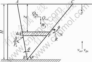
Fig.1 Failure mechanism and associated forces
The pseudo-dynamic analysis, which considers finite shear wave and primary waves, can be developed by assuming that the shear modulus Gs and Gw are constant with depth through the soil backfill and retaining wall. In the present analysis, the shear wave velocity and primary wave velocity acting within the soil backfill due to the earthquake loading can be expressed as
 (1)
(1)
 (2)
(2)
where ρs and  are the density and Poisson ratio of the backfill medium.
Similarly, the shear wave velocity and primary wave velocity acting within the retaining wall can be expressed as
 (3)
(3)
 (4)
(4)
where ρw and  are the density and Poisson ratio of the retaining wall medium.
For the sinusoidal base shaking, the horizontal and vertical acceleration at any depth z and time t, below the ground surface, can be expressed as
 (5)
(5)
 (6)
(6)
The mass of the small shaded part of thickness dz is given by
 (7)
(7)
The weight of the whole failure wedge Ws can then be derived from Eq.(7) and is given by
 (8)
(8)
The horizontal inertia force Qhs acting within the small element due to the horizontal earthquake acceleration can be expressed as

 (9)
(9)
where λ=Tvss, is the wavelength of the vertically propagating shear wave and ζ=t-H/vss. Similarly, the total vertical inertia force Qvs(t) acting within the failure wedge is given by

 (10)
(10)
where η=Tvps, is the wavelength of the vertically propagating primary wave and ψ=t-H/vps.
The total seismic active earth pressure Pa can then be obtained by resolving forces on the failure wedge and considering the equilibrium of the forces. Therefore, the total seismic active earth pressure is given by

 (11)
(11)
The first term in Eq.(11) gives the static active force acting on the retaining wall. The second term in Eq.(11) represents the dynamic active force due to the earthquake loading. It should be noted that the direction of both horizontal and vertical inertia forces shown in Fig.1 causes the most critical effect on the retaining wall under the seismic condition.
The seismic active earth pressure coefficient can then be expressed as
 (12)
(12)
From Eq.(12), it is seen that Ka is a function of α, t/T, H/λ and H/η. H/λ is the ratio of time for a shear wave to travel the full height to the period of lateral shaking T; similarly, H/η is the ratio of time taken by the primary wave to travel the full height to T. For most geotechnical materials, the relation vps/vss=1.87 is appropriate [14]. For concrete gravity retaining wall, it is assumed that =0.15, thus vpw/vsw=1.56 [12]. The period of lateral shaking T=2π/ω is also considered in the analysis, where ω is the angular frequency. For most geotechnical structures, T=0.3 s is a reasonable assumption [15]. Hence, the value of total seismic active force can be determined by optimizing it with respect to α and t/T.
The seismic active earth pressure distribution behind the retaining wall can then be obtained by taking partial derivative of Pa(z, t) with respect to the depth of the wall z thrust as


 (13)
(13)
It is interesting to note that the seismic active earth pressure changes as a non-linear function of depth z. Thus, it is clear that the seismic active earth pressure is non-linearly distributed along the depth of the retaining wall, which is not the case in the pseudo-static analysis. Therefore, the application point of the total active force is no longer at 1/3 height of the wall, which can be determined by taking the moment equilibrium with respect to the base of the wall:
 (14)
(14)
2.3 Determination of safety factor against overturning
The earthquake inertia force acting within the retaining wall should be considered in the design of retaining wall (Fig.2). For a sinusoidal base shaking subjected to both horizontal and vertical earthquake accelerations, the acceleration at any depth z below the ground surface and time t can be expressed as
 (15)
(15)
 (16)
(16)
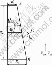
Fig.2 Stability analysis of retaining wall
The total horizontal and vertical inertia forces acting on the wall can be expressed as

 (17)
(17)

(18)
where  is the wavelength of shear wave, and φ=Tvpw, is the wavelength of primary wave through the retaining wall. And ζ=t-H/vsw and χ=t-H/vpw.
According to Code for design of building foundation (GB 50007―2002) [16], the stability against overturning of gravity retaining wall can be described in Kt, which is defined as the ratio between the sum of resisting moments and the sum of overturning moments with respect to the toe of the wall. Considering the effect of earthquake inertia force, the safety factor Kt can be written as
 (19)
(19)
where


3 Results and discussion
The variation of safety factor Kt with changes in kh for different values of θ is presented in Fig.3. It is seen that Kt decreases gradually as kh increases. Also, the safety factor increases with the increase in magnitude of wall inclination.
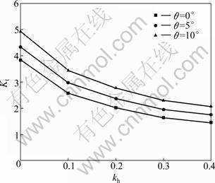
Fig.3 Variations of safety factor of wall stability against overturning Kt with kh for different values of wall inclination θ (δ=10°, f=20°, Bt=3 m, H/λ=0.3, H/η=0.16, H/κ=0.012, H/φ= 0.007 7)
Figure 4 shows the variation of safety factor Kt with horizontal seismic coefficient kh for different values of wall friction angle δ. It is observed that Kt increases as wall friction angle increases for any values of kh. Figure 5 shows the effect of internal friction angle f on the safety factor Kt for kh=0-0.4. From the plot, it can be seen that Kt increases gradually with the increase in internal friction angle f, and the increasing rate is lower for higher values of kh.
Figure 6 shows the variation of safety factor Kt with the horizontal seismic coefficient kh for different values of kv. It is seen that Kt decreases significantly with the presence of horizontal seismic inertia force. The safety factor Kt also decreases with the increase in kv. It is important to note that, the direction of earthquake inertia force shown in Fig.1, causes the total seismic active force to reach the critical value, which may be considered as the most adverse case for retaining wall. The safety factor can be determined by the ratio of the moment against overturning to the overturning moment.
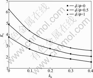
Fig.4 Variations of safety factor of wall stability against overturning Kt with kh for different values of wall friction angle δ (θ=10°, f=30°, kv=kh/2, Bt=3 m, H/λ=0.3, H/η=0.16, H/κ= 0.012, H/φ=0.007 7)
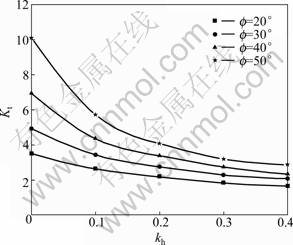
Fig.5 Variations of safety factor of wall stability against overturning Kt with kh for different values of internal friction angle f (H=6 m, θ=10°, δ=f/2, kv=kh/2, Bt=3 m, H/λ=0.3, H/η=0.16, H/κ=0.012, H/φ=0.007 7)
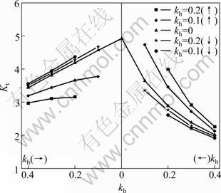
Fig.6 Variations of safety factor of wall stability against overturning Kt with kh for different values of kv (θ=10°, δ=15°, f=30°, Bt=3 m, H/λ=0.3, H/η=0.16, H/κ=0.012, H/φ= 0.007 7)
4 Comparison of results
Figure 7 shows a comparison of safety factor obtained by the present study with that obtained from the Mononobe-Okabe method for θ=10°, δ=15°, f=30°, kv= kh/2, Bt=3 m, H/λ=0.3, H/η=0.16, H/κ= 0.012 and H/φ= 0.007 7. It is observed that the results obtained from the present analysis are larger than the results obtained from the Mononobe-Okabe method for the same set of parameters.
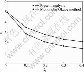
Fig.7 Comparisons of variation of safety factor of wall stability against overturning Kt with kh obtained by present study with earlier investigations
5 Conclusions
1) The main objective of this research is to provide a modified approach for determining the safety factor of wall stability against overturning under seismic loading. The main difference with respect to the traditional solutions is that the seismic inertia force within the retaining wall is considered in the dynamic analysis. The present pseudo-dynamic analysis highlights the time effect of the applied seismic loading and the effect of shear and primary waves traveling through the soil backfill and retaining wall. Unlike the pseudo-static method, the present analysis predicts a nonlinear variation of active earth pressure along the wall. Therefore, the point of application of the total active force under seismic condition is no longer at 1/3 height of the wall.
2) The results of present analysis show that the safety factor increases with the increase in values of wall inclination, wall friction angle, and internal friction angle of the backfill; while it decreases with the presence of horizontal and vertical seismic inertia forces. Both the horizontal and vertical seismic accelerations have substantial effects on the overturning stability.
3) The results based on the presently derived expression propose a higher solution for safety factor of wall stability against overturning thrust compared with the Mononobe-Okabe pseudo-static solution.
References
[1] OKABE S. General theory of earth pressure [J]. Journal of the Japanese Society of Civil Engineers, 1926, 12(1): 1277-1323.
[2] MONONOBE N, MATSUO H. On the determination of earth pressure during earthquake [C]// Proceeding of the World Engineering Congress. Tokyo, Japan, 1929: 274-280.
[3] KRAMER S L. Geotechnical earthquake engineering [M]. NJ: Prentice Hall, Englewood Cliffs, 1996: 1-400.
[4] RICHARDS R, HUANG C, FISHMAN K L. Seismic earth pressure on retaining structures [J]. Journal of Geotechnical and Geoenvironmental Engineering, ASCE, 1996, 125(9): 771-778.
[5] SARAN S, GUPTA R P. Seismic earth pressures behind retaining walls [J]. Indian Geotechnical Journal, 2003, 33(3): 195-213.
[6] SHUKLA S K, GUPTA S K, SIVAKUGAN N. Active earth pressure on retaining wall for c-φ soil backfill under seismic loading condition [J]. Journal of Geotechnical and Geoenvironmental Engineering, ASCE, 2009, 135(5): 690-696.
[7] CALTABIANO S, CASCONE E, MAUGERI M. Seismic stability of retaining walls with surcharge [J]. Soil Dynamics and Earthquake Engineering, 2000, 20: 469-476.
[8] STEEDMAN R S, ZENG X. The influence of phase on the calculation of pseudo-static earth pressure on a retaining wall [J]. Geotechnique, 1990, 40(1): 103-112.
[9] ZENG X, STEEDMAN R S. On the behavior of quay walls in earthquakes [J]. Geotechnique, 1993, 43: 417-431.
[10] CHOUDHURY D, NIMBALKAR S. Seismic passive resistance by pseudo-dynamic method [J]. Geotechnique, 2005, 55(9): 699-702.
[11] GHOSH P. Seismic active earth pressure behind a nonvertical retaining wall using pseudo-dynamic analysis [J]. Canadian Geotechnical Journal, 2005, 45(9): 117-123.
[12] CHOUDHURY D, NIMBALKAR S. Seismic rotational displacement of gravity walls by pseudo-dynamic method: Passive case [J]. Soil Dynamics and Earthquake Engineering, 2007, 27(3): 242-249.
[13] NIMBALKAR S, CHOUDHURY D. Sliding stability and seismic design of retaining wall by pseudo-dynamic method for passive case [J]. Soil Dynamic Earthquake Engineering, 2007, 27(6): 497-505.
[14] DAS B M. Principles of soil dynamics [M]. Boston: Massachusetts, PWS-KENT Publishing Company, 1993: 1-380.
[15] PRAKASH S. Soil dynamics [M]. USA: McGraw Hill, Inc, 1981: 1-450.
[16] GB50007―2002. Specifications for foundation design of construction grounds [S]. Beijing: China Architecture and Building Press, 2002. (in Chinese)
(Edited by YANG Bing)
Foundation item: Project(50879077) supported by the National Natural Science Foundation of China
Received date: 2010-11-19; Accepted date: 2011-03-07
Corresponding author: MA Shao-jun, PhD; Tel: +86-13588103298; E-mail: msj07@zju.edu.cn

