Trans. Nonferrous Met. Soc. China 23(2013) 366-371
Manufacture of μ-PIM gear mold by electroforming of Fe-Ni and Fe-Ni-W alloys
Seong Ho SON1, Sung Cheol PARK1, Wonsik LEE2, Hong-Kee LEE1
1. Heat Treatment & Plating Technology Center, Korea Institute of Industrial Technology, Inchon, Korea;
2. Advanced Fusion Process R&D Group, Korea Institute of Industrial Technology, Inchon, Korea
Received 2 May 2012; accepted 4 November 2012
Abstract: The micro gear mold for powder injection molding was made by electroforming process of Fe-Ni and Fe-Ni-W alloys using UV-lithography process. Kinetics and activation energies in electroplating of both alloys were investigated to determine the best process conditions. Fe content within electrodeposited Fe-Ni alloys increased with the increase of rotating disk speed and the decrease of temperature and it is considered from the calculated activation energy of iron content that the rate determining step is controlled by mass transfer. Iron content in Fe-Ni electrodeposit varied from 58.33% to 70.45% by increasing current density from 2 to 6 A/dm2. Also, iron content in Fe-Ni-W electrodeposit increased from 59.32% to 70.15%, nickel content decreased from 27.86% to 17.07% and the content of tungsten was almost consistent in the range of 12.78%-12.82% although the current density increases from 1.5 to 5 A/dm2. For the electroforming of micro gear mold, SU-8 mandrel with 550 μm in diameter and 400 μm in height was prepared by UV-lithography processing. Subsequently, Fe-36Ni and Fe-20Ni-13W alloys micro gear molds were electroformed successfully. Surface hardness values of the electroformed micro molds were measured to be HV490 and HV645, respectively.
Key words: electroforming; Fe-Ni alloy; Fe-Ni-W alloy; gear mold; PIM
1 Introduction
Recently, ultraviolet (UV) photolithography has been widely used in fabrication of micro parts and micro molds because it is a good technology for fabricating micro structures. For UV lithography, SU-8 is recently used as a photoresist. SU-8 is a high contrast, epoxy- based negative tone photoresist. It is suitable for imaging high aspect ratio structures with near vertical sidewalls. Since the viscosity of SU-8 is very high, different thicknesses from 1 um to 1.5 mm can be obtained by single spin coating process [1]. Moreover, SU-8 has superb chemical property and high thermal stability [2]. So, it is being used in various applications such as mechanical micro components, microfluidic systems, biomedical field and electrical insulation [2-6]. Electroforming process is one of the most useful fabrication techniques, which is suitable for the fabrica- tion of complex-shaped product. Various compositions of Fe-Ni alloys, such as permalloy (80Ni-20Fe), invar alloy (36Ni-64Fe) and high strength Fe-Ni alloy, can be used in electroforming and the resultant alloys show low thermal expansion coefficient and high surface hardness. Hardness was improved due to the precipitation hardening effect and nano-sized grain effect in ternary Fe-Ni-W alloys [7,8]. Electrodeposition reaction can be described as heterogeneous in nature, and the overall reaction consists of a number of sequential steps as convective diffusion, electromigration and electro- chemical reaction at the solution-metal interface. Thus, to obtain the stable properties of deposit, the reaction mechanism has to be investigated and the process factors should be controlled. The reaction mechanism can be examined by LEVICH [9].
In this work, for powder injection molding (PIM) of micro gear and mold was fabricated by electroforming of Fe-Ni alloy using SU-8 mandrel. To obtain an understanding of reaction mechanism involved in electroforming of Fe-Ni and Fe-Ni-W alloys, rotating disk electrode (RDE) was used in electrodeposition process. The surface of the mold was investigated using energy dispersive spectroscopy (EDS), atomic force microscopy (AFM) and micro Vickers hardness test.
2 Experimental
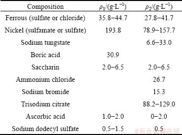
Electrodepositing of Fe-Ni and Fe-Ni-W alloys was carried out using copper RDE of 1 cm in diameter which was wrapped with Teflon dimensionally stable anode (DSA) was used as an anode and a saturated calomel electrode as a reference electrode. The chemical reagents consisted of metal sources, a buffer, a surfactant, a stress reliever, a complexing reagent and an antioxidant: nickel, iron and tungsten as metal sources, boric acid as a buffer, sodium lauryl sulfate as a surfactant, saccharin as the stress reliever, sodium citrate as the complexing reagent, ascorbic acid to prevent oxidation of the ferrous ions. The detailed chemical compositions of electrolytes are listed in Table 1. Applied potential was controlled using a DC power supply (YPP15100A, Yamamoto) or potentiostat (EG&G 273A, Princeton Applied Research).
Table 1 Concentration of chemical reagents in Fe-Ni (ρ1) and Fe-Ni-W (ρ2) alloy solutions
The substrate prior to spin coating of SU-8 was manufactured using silicon wafer. 500 nm-thick Ti and 2500 nm-thick Ni films on silicon were subsequently deposited by conventional e-beam evaporation deposition. SU-8 photoresist was spun on the Ni seed layer substrate and 550 μm in diameter and 400 μm in height was prepared by UV-lithography processing. The electroforming of Fe-Ni alloy was operated at 313 K and the applied current density of 4 A/dm2. The electrodeposited composition was analyzed by EDS (System Six, Noran). The surface properties of Fe-Ni alloy deposit were analyzed using a Vickers hardness tester (Shimazu, HMV-2) and AFM (Pacific Nanotechnology, Nano-R).
3 Results and discussion
Kinetics and activation energies in electroplating of Fe-Ni and Fe-Ni-W alloys were investigated to determine the best process conditions. The effects of temperature on the electrodeposition rate (C) of Fe-Ni alloy were investigated using RDE and the results are shown in Fig. 1. With the increase of temperature, the electrodeposition rates of iron and nickel are increased. To investigate the rate determining step (k), Arrhenius plots which are the relationship between the reciprocal of temperature and the apparent rate constant, for iron and nickel elements, were obtained as shown in Fig. 2. The calculated activation energies of iron were 83.07 J/mol and 8.54 J/mol at the temperature range of 308-318 K and 318-328 K, respectively. Thus, these results indicate that the reaction rate of iron in Fe-Ni alloy deposit was controlled by chemical reaction at temperature of 308-318 K, and then the iron was controlled by mass transport at temperature of 318-328 K. The activation energies of nickel in the alloy deposit were calculated to be 94.58 and 36.51 J/mol at the temperature of 308-318 K and 318-328 K, respectively, implying that the reaction rate of nickel was controlled by chemical reaction at 308-318 K, and then the nickel was controlled by a mixed mechanism, partly by chemical reaction and partly by mass transport at 318-328 K.
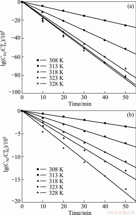
Fig. 1 Variations of electrodeposition rates of iron (a) and nickel (b) in Fe-Ni alloy deposit as function of temperature at 2.75 V and 400 r/min
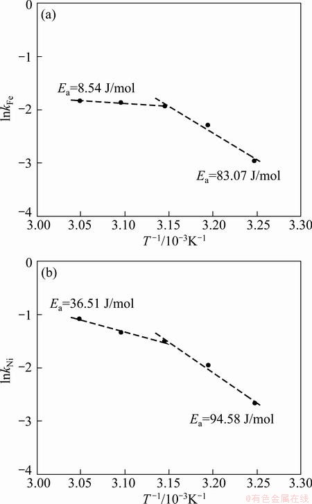
Fig. 2 Arrhenius plots for electrodeposition of elements iron (a) and nickel (b) in Fe-Ni alloy at 2.75 V and 400 r/min
The effects of temperature on the electrodeposition rate of Fe-Ni-W alloy were investigated using RDE and the results are shown in Fig. 3. With the increase of temperature, the electrodeposition rates of iron, nickel and tungsten are slightly increased. To investigate the rate determining step, Arrhenius plots which are the relationship between the reciprocal of temperature and the apparent rate constant, for iron and nickel elements, were obtained as shown in Fig. 4. The calculated activation energy of iron was 22.11 J/mol at 323-348 K. Thus, these results indicate that the reaction rate of iron in Fe-Ni-W alloy deposit was controlled partly by electrochemical reaction and partly by mass transport, namely mixed control. The activation energy of nickel in the alloy deposit was calculated to be 48.69 J/mol, implying that the reaction rate of nickel was controlled by electrochemical reaction. The calculated activation energy of tungsten was 9.09 J/mol, which was controlled by mass transport. Table 2 shows compositions of iron and nickel in Fe-Ni alloys electrodeposited at different current densities. Iron component in Fe-Ni electrodeposits was almost consistent in the range of 69.59%-70.45% with the increase of current density from 2 to 4 A/dm2, while the iron component decreased to 58.33% in the current density of 4-6 A/dm2. In the current density of 2-4 A/dm2, the compositions were similar to those of invar alloys with a low thermal expansion coefficient (mold for micro powder injection molding is required to be stable thermally, i.e. dimensional stability). Table 3 shows the compositions of iron, nickel and tungsten in Fe-Ni-W alloys electrodeposited at different current densities. The iron component in Fe-Ni-W electrodeposits increased from 59.33% to 70.15%, nickel component decreased from 27.86% to 17.07%, the content of tungsten was almost consistent in the range of 12.78%-12.98% although the increase of current density from 1.5 to 5 A/dm2. At the current density of 3 A/dm2, the electrodeposit of Fe-Ni-W alloy showed uniform composition and good surface hardness (HV 645).
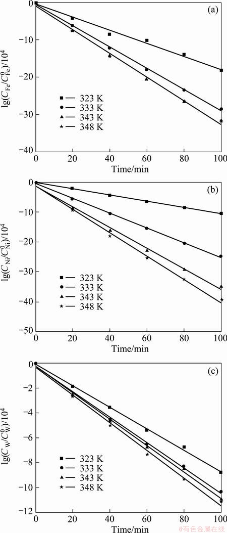
Fig. 3 Variations of electrodeposition rates of iron (a), nickel (b) and tungsten (c) in Fe-Ni-W alloy deposit as function of temperature at 3 V and 400 r/min
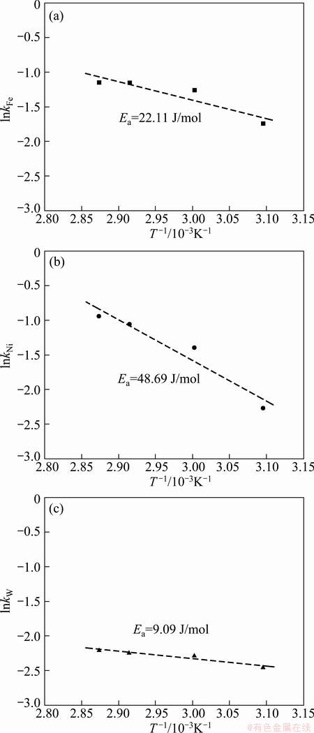
Fig. 4 Arrhenius plots for electrodeposition of iron (a), nickel (b) and tungsten (c) elements in Fe-Ni-W alloy at 3 V and 400 r/min
Table 2 Compositions of iron and nickel in Fe-Ni alloy electrodeposited at different current densities
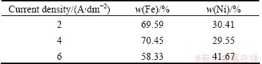
Table 3 Compositions of iron, nickel and tungsten in Fe-Ni-W alloy electrodeposited at different current densities
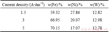
Figure 5 shows the SU-8 mandrels for micro gear and gear mold. This reveals that SU-8 is capable of producing microstructure with vertical sidewall and high aspect ratio. For micro gear and mold of invar alloy composition, electroforming was carried out at bath temperature of 313 K and current density of 4 A/dm2 in electrolyte.
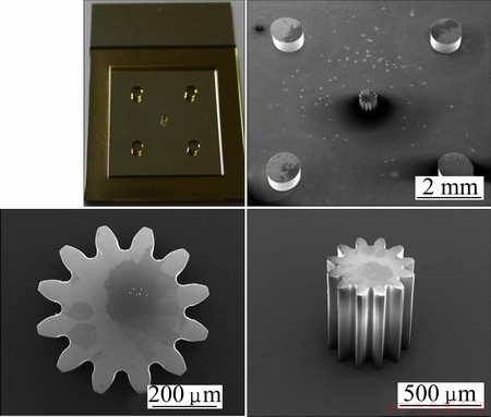
Fig. 5 Photographs and SEM images of SU-8 micro gear mandrels
After electroforming to 400 μm in height, SU-8 mandrel was stripped in n-methyl-2-pyrrolidone (NMP) solution. The electroformed micro gear and mold are represented in Fig. 6. Surface roughness (Ra) of the mold was measured by AFM and the result is shown in Fig. 7. The measured Ra value of electroformed mold was 37.5 nm which was a very excellent value in micro mold. The surface composition was analyzed using EDS and 64.3% Fe and 35.7%Ni were obtained. In micro Vickers hardness test, the surface hardness of the mold was measured to be HV490. This value is nearly three times higher than that in conventional invar alloy, which results from strengthening due to fine grains [10].
4 Conclusions
To investigate rate determining step, activation energies of elements iron, nickel and tungsten in electrodeposition of Fe-Ni and Fe-Ni-W alloys were calculated with Arrhenius plots. The reaction rate of iron in electrodeposition of Fe-Ni alloy was controlled by chemical reaction at 308-318 K, while at 318-328 K, it was controlled by mass transport. The reaction rate of nickel was controlled by chemical reaction at 308-318 K and by a mixed mechanism of chemical reaction and mass transfer at 318-328 K. The reaction rate of iron in electrodeposition of Fe-Ni-W alloy was controlled partly by electrochemical reaction and partly by mass transport, namely mixed control. The reaction rate of nickel was controlled by electrochemical reaction. However, tungsten was controlled by mass transfer. Fe-Ni alloy micro gear molds were electroformed with a very good surface roughness (37.5 nm). The surface composition was analyzed using EDS and 64.3% Fe and 35.7% Ni were obtained. In micro Vickers hardness test, the surface hardness of the gear mold was measured to be HV490. This value is nearly three times higher than that in conventional invar alloy, which results from strengthening due to fine grains.
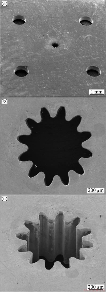
Fig. 6 SEM images of electroformed Fe-Ni alloy micro gear mold
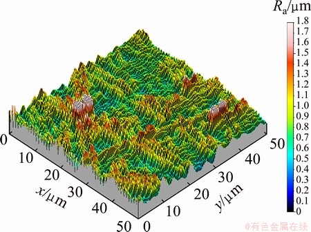
Fig. 7 AFM image of electroformed Fe-Ni alloy micro gear mold surface
References
[1] LIN C H, LEE G B, CHANG B W, CHANG G L. A new fabrication process for ultra-thick microfluidic microstructures utilizing SU-8 photoresist [J]. Journal of Micromechanics and Microengineering,2002, 12: 590-597.
[2] CHUNG C, ALLEN M. Uncrosslinked SU-8 as a sacrificial material [J]. Journal of Micromechanics and Microengineering,2005, 15: N1-N5.
[3] MATA A. Fabrication of multi-layer SU-8 microstructures [J]. Journal of Micromechanics and Microengineering, 2006, 16: 276-284.
[4] HO C H, CHIN K P, YANG C R, WU H M, CHEN S L. Ultrathick SU-8 mold fabrication and removal, and its application of LIGA-like micromotors with embedded roots [J]. Sensors and Actuators A, 2002, 102: 130-138.
[5] SHEW B Y, KUO C H, HUANG Y C, TSAI Y H. UV-LIGA interferometer biosensor based on the SU-8 optical waveguide [J]. Sensors and Actuators A, 2005, 120(2): 383-389.
[6] MALEK C G K. SU8 resist for low-cost X-ray patterning of high-resolution, high-aspect-ratio MEMS [J]. Microelectronics Journal, 2002, 33(1-2): 101-105.
[7] MUN S J, KIM M S, YIM T H, LEE J H, KANG T. Mechanical and structural characteristics of electrodeposited Ni-Fe-W alloy after heat-treatment [J]. Journal of the Electrochemical Society, 2010, 157(3): D177-D180.
[8] DOTEN M, CESIULIS H, STOJEC Z. Electrodeposition and properties of Ni-W, Fe-W and Fe-Ni-W amorphous alloys: A comparative study [J]. Electrochimica Acta, 2000, 45: 3389-3396.
[9] LEVICH V G. Physicochemical hydrodynamics [M]. Englewood Cliffs NJ: Prentice-Hall, 1962.
[10] MCCREA J L, PALUMBO G, HIBBARD G D, ERB U. Properties and applications for electrodeposited nanocrystalline Fe-Ni alloys [J]. Reviews on Advanced Materials Science, 2003, 5: 252-258.
Fe-Ni和Fe-Ni-W合金电铸成型μ-PIM齿轮模具
Seong Ho SON1, Sung Cheol PARK1, Wonsik LEE2, Hong-Kee LEE1
1. Heat Treatment & Plating Technology Center, Korea Institute of Industrial Technology, Inchon, Korea;
2. Advanced Fusion Process R&D Group, Korea Institute of Industrial Technology, Inchon, Korea
摘 要:采用紫外线光刻工艺,将Fe-Ni 和 Fe-Ni-W合金电铸成粉末注射成型用微型齿轮模具。研究电镀过程中2种合金的动力学和活化能,以确定最佳的工艺条件。电沉积Fe-Ni合金中的Fe含量随着转盘速度的加快和温度的降低而增加,从计算得到的Fe组份活化能可以看出,速率控制步骤是传质。在Fe-Ni电沉积物中,随着电流密度由2 A/dm2增加到6 A/dm2,Fe含量从58.33%增加到70.45%。在电流密度从1.5 A/dm2增加到5 A/dm2的过程中,Fe-Ni-W沉积物中Fe含量从59.32%增加到70.15%,而Ni含量从27.86%下降到17.07%,但W的含量保持在12.78%~12.82%的范围。通过电铸,采用紫外线光刻工艺制备了直径550 μm、高度400 μm用于微型齿轮模具的SU-8芯棒。随后,成功电铸成形了Fe-36Ni和Fe-20Ni-13W合金微型齿轮模具,其表面硬度分别为HV490和HV645。
关键词:电铸成型;Fe-Ni合金;Fe-Ni-W合金;齿轮磨具;粉末注射成形
(Edited by Xiang-qun LI)
Corresponding author: Seong Ho SON; Tel: +82-32-850-0242; E-mail: shson@kitech.re.kr
DOI: 10.1016/S1003-6326(13)62471-1

