J. Cent. South Univ. Technol. (2011) 18: 1509-1517
DOI: 10.1007/s11771-011-0867-3
Method of closed loop springback compensation for incremental sheet forming process
HAN Fei(韩飞)1, MO Jian-hua(莫健华)2, GONG Pan(龚攀)2, LI Min(李敏)1
1. College of Mechanical and Electrical Engineering, North China University of Technology, Beijing 100144, China;
2. State Key Laboratory of Material Processing and Die & Mould Technology,
Huazhong University of Science and Technology, Wuhan 430074, China
? Central South University Press and Springer-Verlag Berlin Heidelberg 2011
Abstract: The closed loop control model was built up for compensating the springback and enhancing the work piece precision. A coupled closed loop algorithm and a finite element method were developed to simulate and correct the springback of incremental sheet forming. A three-dimensional finite element model was established for simulation of springback in incremental sheet forming process. The closed loop algorithm of trajectory profile for the incremental sheet forming based on the wavelet transform combined with fast Fourier transform was constructed. The profile of processing tool path of shallow dishing with spherical surface was designed on the basis of the profile correction algorithm. The result shows that the algorithm can predict an ideal profile of processing track, and the springback error of incremental sheet forming is eliminated effectively. It has good convergence efficiency, and can improve the workpiece dimensional accuracy greatly.
Key words: incremental sheet forming; spingback; numerical simulation; closed loop control
1 Introduction
Incremental sheet forming (ISF) is a new technology for flexible process. The process resolves the complicated geometry information into a series of two-dimensional layers, and then the plastic deformation is carried out layer-by-layer through the CNC controlled movements of a simple spherical forming tool to get the desired part [1-4]. Springback is one of the sheet metal forming defects (wrinkling, cracking, and springback), which is the most difficult to control. Many researchers committed to find an effective method to reduce the springback. Trial-and-error, as a traditional method, has been used to compensate the springback. It requires the operator to have high skills and rich experience. It will succeed or not by a certain chance. For complex car body covers, it will take more than several months in the mold pilot stage for repairing the die required for springback compensation [5-6]. As for the incremental sheet forming, according to the researcher’s introduction from AMINO Company, if the parts were wanted to meet the demand incremental sheet forming precision, it required to modify the trace of tool head for about 20 times and it would waste a lot of cost and time.
Numerical simulation method can be used to save cost for mold repairing in the process of compensation and to reduce new product development cycle. KARAFILLIS and BOYCE [7] proposed a spring- forward method, which uses the finite element method to calculate the amount of springback accurately on the mold. GAN and WAGONER [8], according to mold compensation practices by “repeated experiment”, proposed using displacement amendment for die compensation. However, these methods above have a low convergence speed.
WEBB and HARDT [9], from Massachusetts Institute of Technology, firstly proposed the concept of closed-loop forming sheet in 1984. It was the basic principle to introduce feedback control theory from automatic control theory into the field of sheet metal forming. They used the advanced control technology to solve precision sheet metal forming problems [10-11]. The closed loop feedback control method was applied in incremental sheet forming in this work, and the model of springback compensation closed loop revising algorithm for the process was established. It was based on the union algorithm of discrete Fourier transform (DFT) and discrete wavelet transform (DWT). Combined with numerical simulation, the path of surface shape after revised can be forecasted.
2 Model of incremental closed-loop control sheet forming
The process of incremental sheet forming by closed-loop control is a complex multi-variable system. The principle diagram of incremental sheet forming is shown in Fig.1. In mechanics, it involves non-linear stress-strain relationship. In geometry, it refers to large strain problems and the boundary conditions are complex. In the system, there are many variables that affect the forming process, such as the material properties of workpiece, the shape of tool surface, the diameter of tool head, and the single-feed forming process parameters of tool head. Actually, system output is the real shape of formed part. The relationships between them are shown in Fig.2.
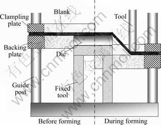
Fig.1 Principle diagram of incremental sheet forming

Fig.2 Relationship of variables in incremental forming process
The relationship between the actual shape of forming part and the above-mentioned factors can be expressed as
 (1)
(1)
where S is the shape of the formed work piece, P is the envelope surface of tool head track, F is the friction conditions, and σs is the yield stress of plate.
The actual shape of the forming workpiece has relationships with the trajectory envelope shape, forming process parameters, as well as the material of work- pieces and many other factors (as shown in Fig.2). However, the material properties of workpiece are usually determined for a particular product. So, the workpiece geometry p relates with the trajectory envelope surface shape d, and the forming process parameters Γ. The relationship of them could be expressed as
p = f(x) (2)
where x=(d, Γ), referred to the forming state-point, d0 is the initial trajectory envelope surface shape parameter and Γ0 is the initial forming process parameter. Springback compensation is actually the amendment of d0. The revised trajectory envelope surface shape could be expressed as d0+Δd. Springback compensation would affect d0 very slightly if the forming process parameters Γ remain unchanged. There must be a state d0+ΔΓ in the vicinity of the initial state point x0, which is just able to compensate for springback caused by the size of the error. Equation (2) in the initial state point x0 for Taylor is
 (3)
(3)
If the forming process parameters Γ0 maintain unchanged and the high-end terms are omitted, Eq.(3) can be expressed as
 (4)
(4)
 (5)
(5)
where  is called the transfer function.
As the trajectory of incremental forming tool head could be adjusted according to the target shape, the surface shape of workpiece is measured after unloading. The measured shape would be regarded as the feedback which is used to amend tool path of the process until the workpiece and target shape are consistent. Figure 3 shows the springback compensation model in the actual incremental forming process with the closed loop numerical control incremental forming.
The target shape of forming pieces is p*. di is the CAD model which is used to generate the trajectory for the first time forming, and pi is the formed parts shape. Δdi=di-di-1, is the rectification of current trajectory envelope shape. Δpi=pi-pi-1, is the change of current workpiece shape, and ei=p*-pi, is the shape error of workpiece. Γ is the forming process parameter.
Incremental sheet forming process is essentially discrete. It is difficult to measure parts surface on-line, giving birth to a certain lag feedback. Therefore, an incremental form can be expressed as control model (see Fig.3). Through linearizing the incremental forming process, the incremental sheet forming closed loop control model is shown in Fig.4, where gp is the forming process transfer function and gc is the controller.
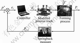
Fig.3 Feedback control model of closed loop numerical control incremental forming

Fig.4 Incremental sheet forming model of closed-loop control system
3 Closed loop compensation algorithm of path surface based on Fourier and wavelet transform
3.1 Fourier transform and wavelet transform
3.1.1 Discrete Fourier transform
During the closed loop forming process, input and output volumes are the shapes of the three-dimensional forming parts. Target shape is given by the CAD. The system or the actual forming shape is obtained by the three-dimensional laser measuring instrument, referred to plane separate matrixes. A matrix expresses a surface shape. The partial distortion can affect the adjacent area in the actual processing. The separate matrix describes the forming surface in the forming process. In other words, mutual coupling surfaces of the control subsystems are decoupled compulsively in the forming process. Each control subsystem is single input-output subsystem and has nothing to do with other subsystems. The forming error only reflects partial characteristic of the workpiece without considering the whole forming characteristic of the workpiece. The spatial distribution surface shape is transformed to the spatial frequency domain by two-dimensional discrete Fourier transform (DFT). By computing the corresponding frequency spot in closed loop control subsystem, the overall characteristic of forming workpiece can be known. The envelope shape of tool path can be found through inversing transformation to controller’s output.
The Fourier transformation establishes the transformation bridge of discrete magnitude from time domain to frequency domain, and inverse Fourier transform establishes the transformation bridge of discrete magnitude from the frequency domain to the time domain. They correspond with each other [12]. Fourier transformations can describe three-dimensional surface signals. In case of three-dimensional surface, samples that are separate two-dimensional signals in space position are taken. The number of sample points on x-axis direction is M, whose interval is Δx. And the number of sample points on y-axis direction is N, whose interval is Δy. Discrete surface is still f(x, y), but its meaning becomes
f(x, y)=f(xΔx, yΔy),
x=0, 1, 2, …, M-1; y=0, 1, 2, …, N-1
Its discrete Fourier transform is
f(u, v)=f(uΔu, vΔv),
u=0, 1, 2, …, M-1; v=0, 1, 2, …, N-1
The discrete Fourier transform is given by

u=0, 1, 2, …, M-1; v=0, 1, 2, …, N-1 (6)

x=0, 1, 2, …, M-1; y=0, 1, 2, …, N-1 (7)
In discrete Fourier transform, the total number of spectrum points is equal to the total number of samples, and also they compose a matrix form. Sample interval Δx, Δy in spatial domain correspond with spectrum interval Δu, Δv in spatial frequency domain:
 (8)
(8)
The Fourier transformation establishes the transformation bridge from time domain to frequency range. Fourier transform is a signal analysis and signal processing technology, which is the theoretical basis for the steady-state signals. Whereas, the Fourier transformation involves the entire transformation for the whole time axis, and reflects the frequency statistical property in entire time signal axis, which cannot supply any frequency information of partial time section. Fourier transformation does not have the ability of demarcation measure for local distortion. In other words, the Fourier analysis is only overall statistics for signal. It is insufficient for non-steady signal analysis and signal processing timely. Therefore, it is not suitable to analyze nonlinear signal. Generally, it is used to analyze linear signal and quasi-linear signal [13-14].
In this work, the varying function from the tool path surface to the workpiece surface in separate closed loop control system is focused on. This variety is a highly non-linear problem caused by springback. Obviously, it will cause characterization error in signal processing with Fourier formula. The whole system precision will drop, which is caused by the leakage of spectrum in signal transmission, especially the workpiece with flat surface.
3.1.2 Wavelet transformation based on fast Fourier transform
Discrete wavelet transform (DWT) has time- frequency partial characteristic. It has high frequency resolution and low time resolution in the low frequency, and it is opposite to high-frequency domain. Because the width of time and frequency window can be adjusted, it is fit for detecting jump and non-steady signal [15]. Meanwhile, it can produce functions by expansion and translation as
 (9)
(9)
where Ψ is the wavelet base function. Function {Ψab} deriving from Ψ is called as wavelet. The scale parameter, a, can change the frequency bandwidth of filter. The location parameter, b, can decide time domain information in transform result. Therefore, the wavelet function has both frequency characteristic and time domain localization characteristic.
In this work, combining Fourier and wavelet transform algorithm for incremental sheet forming is used to realize the transform from surface time domain to frequency domain, making full use of the advantage of wavelet and Fourier transform. It could get more comprehensive and accurate time-frequency information of the surface on forming workpiece for reducing the frequency spectrum leakage. This reduces the feedback control iteration times of springback, improves the convergence, and satisfies the project practical application need.
3.2 Closed loop compensation algorithm of incremental sheet forming path surface based on DFT and DWT
According to the analysis above, the gain of control system can be determined (k=gcgp=1):
 (10)
(10)
Then, the relationship between controlling process transfer function gc and forming process transfer function gp is determined. As a result, the forming process is combined with the controlling process.
According to the preamble linearized supposition in forming process and the invariable forming parameter, variable quantity of path envelope shape, Δd, and variable quantity of forming workpiece, Δp, have linear relationship approximately, when they are very small. When Δd is very small, scale factor gp can be gained through system identification under open loop forming with two times. Approximation can be gotten.  is close to gp:
 (11)
(11)
Therefore,
 (12)
(12)
In order to get shape transfer function (gp) easily, spatial surface shape is transformed to spatial frequency domain, based on discrete Fourier wavelet transform for three-dimensional surfaces. Compared with the description of surface separate matrix, the whole forming part characteristic could be reflected by compensated operation for the corresponding frequency domain point. W(fft2(・)) refers to surface data based on Fourier wavelet transform. Under open loop control system forming condition, d1 and d2 refer to path envelope shapes in time domain; W(D1) and W(D2) refer to path envelope shapes corresponding with d1 and d2 in frequency domain; p1 and p2 refer to shapes of forming workpiece in time domain; W(p1) and W(p2) refer to shapes of forming workpiece corresponding with p1 and p2 in frequency domain:
 (13)
(13)

 i=1, 2
In summary, increasing model in Fig.4 can be further consummated, as shown in Fig.5. There are two improvements. Firstly, the relationship between gc and gp can be established through system identification. Secondly, surface is described based on discrete Fourier wavelet transform instead of discrete matrix.
In the first compensation for revision (path envelope shape d* is requested corresponding to target forming shape p*), the revising error of path envelope shape is Δd* (Δd*=d*-d1), and the revising error of the forming shape is Δp*=p*-p1. Then, the surface can be described by discrete Fourier transform:

 (14)
(14)
 (15)
(15)
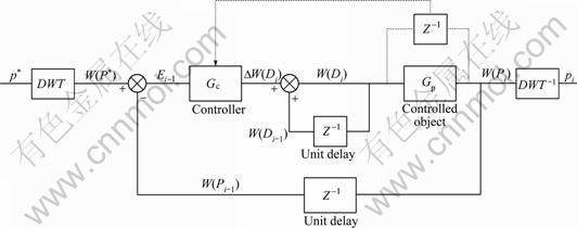
Fig.5 Closed loop incremental control model based on DFT and DWT algorithm
W(D*) could be worked out according to the formula based on W(P*), W(D1), W(P1), W(D2) and W(P2). Set of points d* of ideal trajectory envelope discrete data could be obtained through wavelet inversing transform to W(D*). Regarding the sheet numerical control incremental forming, the tool head trajectory is revised. The high precision compensation for springback can be achieved. In this work, software of Matlab is used as a platform. It can realize spingback surface closed loop revising algorithm for incremental sheet forming through writing program, based on DFT Fourier transform and DWT wavelet transform union. The flow chart is shown in Fig.6.
The system control process is described as follows:
1) Suppose that p* is the ideal product shape, d1 and d2 are designed by numerical simulation or experience, in which spingback is small.
2) Unchange the processing parameter, p1 and p2 are obtained according to d1 and d2 experiments through open loop control system experiment. If the shape error of p1, p2 and p* is below a reference quantity ε, the path envelope surface has already met the requirement. d1 or d2 is used to process without revising.
3) If the shape error of p1, p2 and p* is above a reference quantity ε, spingback will influence the forming precision greatly. The path envelope surface must be revised in order to increase the forming precision.
4) According to p1, p2 and d1, d2, the forming process transfer function Gp is obtained through the Fourier transform and wavelet transform.
5) The wavelet form of ideal trajectory surface d* can be obtained through function Gp. Set of points of the ideal trajectory surface can be gotten by using Fourier and wavelet inverse transform to d*.
6) By restructuring set of points of the ideal trajectory surface, the ideal trajectory surface shape can be obtained.
4 Confirmation of surface compensation algorithm
4.1 Realization of springback compensation algorithm based on numerical simulation
Based on open loop experiment of two times, the path surface was revised and the workpiece could be processed well. This process consumed financial resource and time greatly. With the development of computer hardware and software technique, the finite element numerical simulation technology was applied to sheet forming domain successfully.
In this work, a three-dimensional, elasto-plastic finite element model was set up for the simulation of the ISF process. The ISF process was simulated by using ABAQUS/Explicit (a dynamic explicit code), and the results were transferred to ABAQUS/Standard (an static implicit code) to simulate the springback step (tools removal). Square blanks were 1 mm in thickness by 330 mm×330 mm. The blank material was 08Al, which has been meshed with 14 400 4-node shell elements (Abaqus type S4R) with five integration points through the thickness. The material was assumed to be planar anisotropic following Hill’s 1948 yield criterion with kinematic hardening. The tool, partial die, clamping plate and backing plate were modelled as rigid surfaces, the tool diameter was 10 mm, and the shape of partial die was the same as the profile of workpiece. Coulomb’s friction law was applied with a friction coefficient of 0.05 between the blank and the tool and of 0.15 between the blank and the partial die. The contact condition was implemented through a pure Master-Slave contact algorithm.

Fig.6 Spingback closed-loop control flow chart based on DFT and DWT
In order to synchronize the FE simulation with the experiment, the NC file from the actual experiment was imposed into the simulation to move the forming tool. The tool movement was controlled using predefined displacement constraints in several load steps. Using an artificially high tool velocity to substitute for the real process was considered a potentially good method to shorten the simulation time. So, an artificially increased tool feed rate was utilized, equal to 2 000 mm/s. The simulation time was reduced significantly as the tool velocity was increased by up to 10 times. Incremental forming spingback compensation through the path surface closed loop revising algorithm of numerical simulation was realized, DFT and DWT. The simulation iteration compensation method saved much time and cost.
The geometry of workpiece with spherical surface was remarkable. The datum for calculating springback error was the spherical surface apex in this work. The tool path surfaces were standard spherical for the two times open loop simulation. Their structures are shown in Fig.7, and the geometry size can be seen in Table 1. As the workpiece geometry was symmetrical, the two- dimensional shape could represent the entire three- dimensional shape in the workpiece symmetrical section. In order to reduce the calculation times, path surface shape A was the target workpiece shape.
4.2 Revising process of tool path surface
Using finite element numerical simulation for virtual machining to the designed open loop forming path, the deviation from true shape of spingback could be obtained. The comparison of forming shape and target shape is shown in Fig.8. In order to reduce workpiece shape error and according to the numerical simulation result, closed-loop control algorithm based on the wavelet transform in combination with the Fourier transform was applied to revise the processing path surface. The two-dimensional surface data were needed firstly. Sample points were expressed with matrix. Tool path surface and final shape of workpiece surface were described with the two-dimensional Fourier frequency domain by MATLAB Fourier transform function. Discrete wavelet transform data of the track surface were converted into regular times of track surface discrete data by using FFT for discrete wavelet transform and inverse transform. The description of the sample data for track surface and forming workpiece surface from time domain to frequency domain is shown in Fig.9. To obtain a shape identical with the shape of workpiece d1, closed loop control algorithm predicted the surface shape of the corresponding trajectory d*. From Eq.(15) the following function can be obtained:
 (16)
(16)
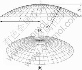
Fig.7 Schematic drawing of path surface structure in simulation model
Table 1 Structure size of path surface
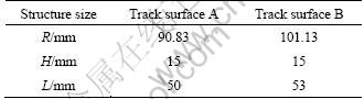

Fig.8 Schematic drawing of two-times open loop forming error curve: (a) Comparison of forming shape and target; (b) Forming error distribution shape
The prediction of path surface geometrical shape could be obtained through inversion transform for computed result of Eq.(16).
According to two-times open loop experiments to revise the path surface for the first time, the forming surface shape could be simulated according to the revised path surface. Forming error distribution was obtained through comparing the two-dimensional line of the forming shape and target shape. The next revision would be executed if the error was still large after the first path revision. The iterative revision of the path surface would be stopped until the shape satisfied the forming precision. Then, ideal tool path surface shape could be obtained. Using the obtained ideal path surface shape to process, the final forming workpiece should have a high precision. The expected workpiece shape and the three-times revised path surface based on two-times open loop experiment are shown in Fig.10.
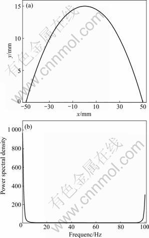
Fig.9 Path surface according to time domain and frequency domain: (a) Surface signal (time domain); (b) Spectrograph (frequency domain)
Numerical simulation was used to simulate the path surface shape forming process with the standard shape instead of the path surface shape. As can be seen in Fig.11 and Fig.12, the workpiece springback was very large. The largest surface altitude error was 3.06 mm, and the surface root-mean-square error also reached as high as 0.65 mm. Therefore, revision to the path surface was essential.
The first path revising surface based on the inferential reasoning closed loop forming algorithm was taken to simulate the processing forming path surface. In Table 2 and Fig.13, the forming path surface was revised through a closed loop process. The largest surface error was reduced to 1.29 mm from 3.06 mm, the root-mean-square error was reduced to 0.48 mm from 0.65 mm, and the error between forming shape and target shape was also reduced. To further reduce the forming error, the second path surface revision based on the first closed loop forming was used. According to the simulation result, the forming workpiece shape approached to the target shape. The largest surface error was 0.58 mm, and the root-mean-square error was 0.15 mm. After the third closed loop forming simulation, the workpiece largest surface error already dropped to 0.22 mm, and the root-mean-square error was reduced to 0.09 mm. The surface error was reduced gradually under three simulation circulation iterations, approaching to the target shape gradually. The forming precession was enhanced greatly. The springback error revised compensating algorithm for incremental sheet forming, based on the Fourier and the wavelet transform, is feasible.

Fig.10 Target shape and revised path surfaces

Fig.11 Numerical simulation results of spherical surface of closed loop incremental forming

Fig.12 Error distributions of spherical surface of closed loop incremental forming
Table 2 Spherical surface closed loop forming error
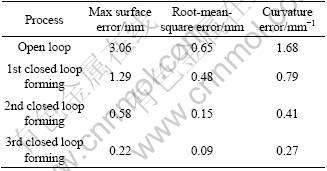
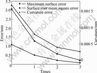
Fig.13 Error convergent curves of spherical surface of closed loop incremental forming
5 Conclusions
1) The closed loop control fundamental model is established to reduce the springback and enhance the incremental sheet forming precision. The relationship between the controlling process transfer function and the forming process transfer function is determined by the control system performance analysis, and the essential condition of system convergence is obtained.
2) The revised algorithm of path of surface closed loop incremental sheet forming based on the Fourier and wavelet transform is proposed. The algorithm can forecast the ideal tool path surface shape, which realizes the compensation for the springback error of incremental sheet forming.
3) Numerical simulation is combined with the closed loop control algorithm to compensate the springback, which realizes the closed loop revision of tool path envelope surface in the incremental sheet forming process. The method is applied to design of tool path surface for the workpiece with shallow dishing shape. The largest dimensional deviation is reduced to 0.22 mm from 3.06 mm through three iterations. Therefore, it is confirmed that this method is effective and feasible to eliminate the springback error in the incremental sheet forming process and enhance the dimensional accuracy of the workpiece greatly, and can reduce times of trial and error in traditional incremental sheet forming.
References
[1] MO Jian-hua, HAN Fei. State of the arts and latest research on incremental sheet NC forming technology [J]. China Mechanical Engineering, 2008(4): 491-497. (in Chinese)
[2] HAN Fei, MO Jian-hua, GONG Pan. Incremental sheet NC forming springback prediction using genetic neural network [J]. Journal of Huazhong University of Science and Technology: Nature Science, 2008(1): 121-124. (in Chinese)
[3] HAN Fei, MO Jian-hua. Numerical simulation and experimental investigation of incremental sheet forming process [J]. Journal of Central South University of Technology, 2008, 15(5): 581-587.
[4] JESWIET J, MICARI F, HIRT G, BRAMLEY A, DUFLOU J, ALLWOOD J. Asymmetric single point incremental forming of sheet metal [J]. Annals of CIRP, 2005, 54(2): 623-649.
[5] FILIPPO P, ROBERTO V, FLAVIO C, FRANCESCA C. An efficient approach to springback compensation for ultra high strength steel structural components for the automotive field [C]// Proceedings of the International Conference on New Developments on Metallurgy and Applications of High Steels. Buenos Aires, 2008: 193-206.
[6] HU Yang, NAGARAJARAO MANJUNATH S, ZHU Xin-hai. A springback compensation study on Chrysler 300C stamping panels using LS-DYNA?[J]. SAE International Journal of Materials and Manufacturing, 2009, 1(1): 800-808.
[7] KARAFILLIS A P, BOYCE M C. Tooling and binder design for sheet metal forming processes compensating springback error [J]. Int J Mech Tools Manufact, 1996, 36(4): 503-526.
[8] GAN W, WAGONER R H. Die design method for sheet springback [J]. International Journal of Mechanical Sciences, 2004, 46: 1097-1113.
[9] WEBB R D, HARDT D E. Spatial frequency based closed-loop control of a sheet forming process[C]. ASME, 1984: 137-152.
[10] LI Ming-zhe, CAI Zhong-yi, LIU Chun-guo. Flexible manufacturing of sheet metal parts based on digitized-die [J]. Robotics and Computer-Integrated Manufacturing, 2007, 23(1): 107-115.
[11] PAN Ming-cun, LIU Chun-guo, LI Ming-zhe. Forming error control in multi-point forming based on 3-D shape feedback [J]. Journal of Plasticity Engineering, 2007, 14(3): 16-19. (in Chinese)
[12] OSGOOD Brad. The Fourier transform and its applications [M]. Stanford University, 2009.
[13] HUANG Xing-jiu, CHOI Yang Kyu, YUN Kwang Seok, YOON Euisik. Oscillating behaviour of hazardous gas on tin oxide gas sensor: Fourier and wavelet transform analysis [J]. Sensors and Actuators B: Chemical, 2006, 115(1): 357-364.
[14] PAN Shih-yu, HSIEH Bieng-zih, LU Ming-tar, LIN Zsay-shing. Identification of stratigraphic formation interfaces using wavelet and Fourier transforms [J]. Computers & Geosciences, 2008, 34(1): 77-92.
[15] DEBNATH L. Wavelet transforms and their applications [M]. Birkhauser, 2007.
(Edited by YANG Bing)
Foundation item: Project(50175034) supported by the National Natural Science Foundation of China
Received date: 2010-07-27; Accepted date: 2011-02-23
Corresponding author: HAN Fei, Associate Professor, PhD; Tel: +86-10-88801107; E-mail: hanfei@ncut.edu.cn

