DOI: 10.11817/j.issn.1672-7207.2020.09.029
涡流发生器布置位置对小型垂直轴风力机气动性能的影响
张立军,朱怀宝,胡阔亮,顾嘉伟,缪俊杰,江奕佳,李想,于洪栋,刘静
(中国石油大学(华东)机电工程学院,山东 青岛,266580)
摘要:为提高垂直轴风力机的气动性能,针对小型双叶片H型垂直轴风力机,提出3种涡流发生器在叶片表面安装位置方案。建立风力机整机仿真模型并进行了网格独立性验证。利用ANYSY FLUENT软件对垂直轴风力机进行三维流体力学仿真研究。研究结果表明:在上风区叶片内表面和下风区叶片外表面加装涡流发生器均可提高叶片的转矩系数,但分析流场显示下风区流场紊乱,下风区叶片外表面加装涡流发生器提升效果变差。3种方案中,叶片内外表面加装涡流发生器时垂直轴风力机风能利用率CP提升效果最好,与原型风力机相比CP提升6.4%。
关键词:垂直轴风力机(VAWT);涡流发生器(VG);布置位置;气动性能;FLUENT软件
中图分类号:TK83 文献标志码:A
文章编号:1672-7207(2020)09-2634-09
Effect of arrangement position of vortex generator on aerodynamic performance of small vertical axis wind turbine
ZHANG Lijun, ZHU Huaibao, HU Kuoliang, GU Jiawei, MIAO Junjie, JIANG Yijia, LI Xiang,YU Hongdong, LIU Jing
(College of Mechanical and Electronic Engineering, China University of Petroleum, Qingdao 266580, China)
Abstract: In order to improve the aerodynamic performance of VAWT, for a small double-blade H-type vertical axis wind turbine, three kinds of arrangement position schemes of vortex generator on the blade surface were proposed. The simulation model was established for the wind turbine, and the grid independence was verified. By using ANYSY FLUENT software, three-dimensional hydrodynamic simulations of conventional airfoils were performed. The results show that the blade torque coefficient can be improved by adding vortex generators on the inner surface of the upwind zone and the outer surface of the downwind zone, but the analysis of the flow field shows that the flow field in the downwind zone is disordered, and the lifting effect of vortex generator installed on the outer surface of the blade in the downwind area becomes worse. Among the three schemes, when the vortex generator is installed on the inner and outer surface of the blade, the wind energy utilization ratio CP of the vertical axis wind turbine is the best, and the wind energy utilization ratio is increased by 6.4% compared with CP of the original wind turbines.
Key words: vertical axis wind turbine(VAWT); vortex generator(VG); arrangement position; aerodynamic performance; FLUENT software
根据风轮旋转轴与地面的几何拓扑关系来划分,风力发电机分为水平轴风力机(HAWT)与垂直轴风力机(VAWT)。垂直轴风力机以其结构简单、无需对风、不需要偏航机构等优点逐渐受到人们的青睐[1]。然而由于VAWT流场结构比HAWT的更加复杂,属于典型的大分离非定常流动,这导致VAWT的整体性能难以提升,尤其是风能利用率较低[2-5],当前垂直轴风力机实际风能利用率为33%~35%,远低于理论值64%[5],使得垂直轴风力机的大型化和商业化发展和应用受到了较大阻碍[6-7]。针对垂直轴风力机风能利用率低的问题,各国专家学者在改进风力机翼型和局部流动控制[8-10]等方面进行了大量研究。VG(vortex generator)涡流发生器一般指的是布置在叶片表面上的一系列小展弦比小翼,最早由TAYLOR[11]提出,这些小翼与来流风向有一定的夹角,气流流过小翼会产生漩涡,将附面层外部动能较高的流体带入边界层内,起到延迟甚至消除附面层分离的作用。目前,国内外学者均对VG进行了较多研究。TIMMER等[12]通过实验方法,研究了不同雷诺数下DU系列风力机专用翼型加装VG前后气动特性的变化,研究结果显示VG可以推迟失速攻角,提高升阻比。ALLAN等[13]对平板上的VG进行了实验与多种湍流模型下的CFD数值仿真研究,结果表明,SST k-w湍流模型对VG产生的涡旋轨迹和峰值涡度衰减率有更好的模拟效果,但涡旋扩散速度比实验中观察到的要快得多。KHALFALLAH等[14]对NACA 63200翼型水平轴风力机加装VG前后进行了实验研究,结果显示VG可以延缓失速,提高翼型的最大升力系数,并且矩形VG比三角形VG更有利于提高风力机的输出功率,在年平均风速较低的情况下可以提高10%~35%。倪亚琴[15]通过实验研究了1 Ma(Ma为马赫数)范围内VG对附面层的影响,结果表明加装VG之后使得下游的附面层厚度变薄,但影响范围有限。张立军等[16]通过数值仿真研究了VG不同参数对垂直轴风力机气动性能影响,并给出了VG最佳设计参数。上述关于VG的研究结果都不同程度地指出加装VG可以提升叶片翼型的气动性能。然而目前VG的相关研究多集中于航空翼型或水平轴风机,在垂直轴风力机领域的研究较少,并且没有考虑VG在垂直轴风力机叶片表面的布置方式。垂直轴风力机与水平轴风力机结构差异较大,叶片表面加装VG对垂直轴风力机气动性能的提升效果仍有待探讨。同时考虑到垂直轴风力机气流流动方式,需要分风区来讨论VG的布置状况。因此,为了更好地分析垂直轴风力机叶片表面加装VG的气动性能,本文作者将利用ANSYS FLUENT软件,针对加装VG的小型H型垂直轴风力机进行三维CFD仿真,深入探讨叶片压力面、吸力面加装VG对垂直轴风力机的气动性能影响。
1 风力机模型
1.1 风力机参数及VG模型
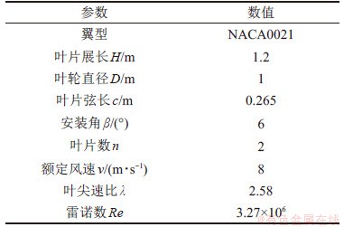
本文所研究采用的H型垂直轴风力机模型为日本三重大学实验模型,其参数如表1所示[17]。
表1 垂直轴风力机的主要参数
Table 1 Parameters of VAWT
本文选用VGs的形状为梯形[18],安装方式为反偏型安装[19],VG下底高度h=3 mm,上底高度h′=2.1 mm,长度l=7.5 mm,安装角度γ=15°,间距d=7.5 mm,排列间隔D=30 mm,VG各项参数定义如图1所示。
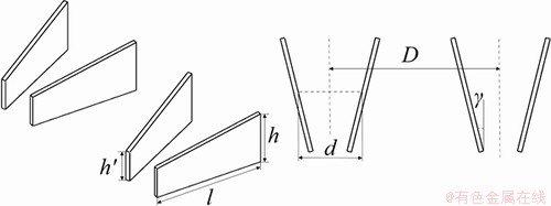
图1 VG几何形状参数
Fig. 1 Geometric shape parameters of vortex generator
VG安装位置是影响翼型气动性能的一个重要参数,一般VG安装位置在8%c~12%c处[20]。本文分析后选择VG安装位置在10%c处,即x/c=10%,叶片双面加装VG的三维图如图2所示。
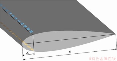
图2 叶片双面加装VG的三维图
Fig. 2 Three-dimensional diagram of double-sided addition of vortex generator to blade
1.2 加装VG方案确定
为研究VAWT叶片表面加装VG对其气动性能影响,首先要确定叶片表面布置VG的方案。VG原理是安装在翼型的吸力面,有效地阻止气流分离过早发生,目前对于水平轴风力机叶片加装VG的研究已经较常见,对于HAWT而言,不论是上风向还是下风向,叶片的迎风面(也就是流动发生分离的表面)是确定的,因此,在该面上布置VG即可;而对于垂直轴风力机却不同,如图3(a)所示,与转轴相对的叶片表面为内表面,另一表面为外表面。在VAWT的旋转过程中,对VAWT建立模型如图3(b)所示。其中, 为叶片旋转角速度;W为相对风速,是叶片相对来流风的速度;
 为叶片方位角,其中当
 时称为上风区,当
 时称为下风区[21];
 为叶片攻角,是叶片弦线方向与相对风速方向间的夹角。在风轮旋转1周过程中,相对风速W的作用表面是不一定的。一般在上风区时,攻角大于0°,此时流动分离就发生在内表面,即内表面为吸力面;在下风区时,攻角小于0°,此时,流动分离发生在外表面,即外表面为吸力面[22]。
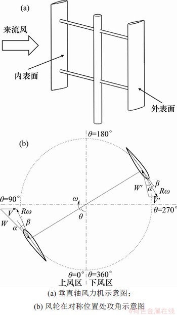
图3 垂直轴风力机模型图
Fig. 3 Model diagram of vertical axis wind turbine
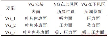
因此,考虑到垂直轴风力机工况的特殊性,本文在垂直轴风力机不同表面加装VG,根据安装表面的不同,提出3种VG安装方案,如表2所示。
表2 VG布置方案
Table 2 Vortex generator arrangement scenario
2 CFD数值模拟计算
2.1 模型建立与网格划分
本文垂直轴风力机数值模拟采用三维计算模型[23-24],首选根据选用的垂直轴风力机模型参数,建立三维垂直轴风力机模型,并将其导入ICEM中进行网格划分。计算域二维截面示意图如图4所示,考虑转轴对风机内部流场的影响,分为外流域和旋转域2个部分。为了更方便建立BLOCK并能有效提高叶片周围网格质量,旋转域进一步划分成4个区块(Domain1~4);考虑到VG尺寸较小,特意在VG附近单独分块,用于生成VG及其周围的网格。为实现旋转域和外流域的相对转动,采用滑移网格技术,定义各域的边界均为交界面(Interface)。为了保证计算精度,设置风力机旋转中心与来流入口处的距离为5D,与出口处的距离为10D,与壁面边界的距离为5D,计算域高度为风力机实际高度1.2 m,风力机顺时针方向旋转。设置VG为零厚度平面,在进行不同方案的CFD仿真时,只需在边界条件设置时修改VG的边界条件(wall和interior)即可[25],这样避免了多次建立加装VG的整机模型以及接下来的网格划分,同时防止了不同网格产生的仿真误差。
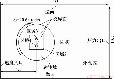
图4 数值模拟计算域划分示意图
Fig. 4 Schematic diagram of numerical simulation domain partition
翼型表面划分边界层网格,第一层网格厚度 [26]由下式确定:
 (1)
(1)
式中:L为特征长度,其值为叶片弦长(m);y*为量纲一的壁面距离;Re为雷诺数。式(1)显示出 y与y*成正比例关系,为保证y*<1,在划分网格时设置y为0.01 mm。
计算域网格如图5所示,其中图5(a)所示为整体网格示意图,图5(b)所示为VG附近区域网格示意图。
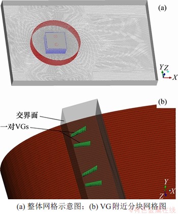
图5 网格示意图
Fig. 5 Grid diagram
2.2 网格独立性与准确性验证
针对该外流场模型,研究发现k-w SST模型相对其他湍流模型能更好地反映流场特征[27-28],得到的结果与实验值较吻合,因此,本节数值仿真采用k-w SST模型。通过改变间隔和边界层高度,加密翼型边界层和旋转域部分网格,实现不同数量网格的划分,并对计算域网格进行独立性验证。采用M_1,M_2,M_3和M_4这4种不同密度的网格,其网格数量及仿真得到的风轮旋转1周平均转矩系数CM,ave如表3所示。
表3 垂直轴风力机网格信息
Table 3 Grid information of vertical axis wind turbine
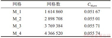
基于表3中数据,整理得到4种方案下CM, ave的变化曲线,如图6所示。从图6可以看出:仿真计算得到的CM, ave与网格数量成正比,当网格数目从160万个增加到430万个时,CM, ave收敛于0.055 6左右。结果表明,M_1和M_2与M_4相比误差较大,而M_3与M_4之间的相对误差小于1%,为获得精度较高的数值模拟结果,并更好地观察叶片表面流场的变化情况,本文控制计算模型的网格数量在430万个左右。
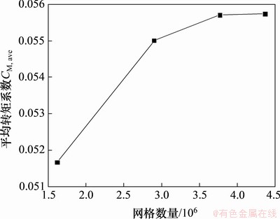
图6 不同网格数量下的叶片转矩系数
Fig. 6 Blade torque coefficient under different mesh numbers
为验证CFD仿真的准确性,将CFD仿真数据与日本三重大学风洞试验数据[17]进行对比。图7所示为VAWT单叶片旋转1周转矩系数CMl随方位角θ变化曲线仿真值与实验值的对比图。从图7可以看出:由于缺少旋转轴及支撑杆相关参数,本文建立的三维VAWT模型忽略了旋转轴及支撑杆等因素对风力机性能的影响,所以在局部方位角下仿真值与实验值有所偏差,但是CFD仿真计算的结果与试验值整体吻合良好,变化趋势也基本保持一致。
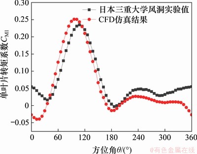
图7 实验值和CFD仿真值的对比
Fig. 7 Comparison between experimental value and CFD simulation value
3 加装VG前后风力机性能分析
本文主要研究VAWT不同表面加装VG对其气动性能的影响,针对表2中3种不同设计方案,首先研究VG安装表面对VAWT叶片转矩系数的影响,然后计算其风能利用率,得到最佳的VG安装方案。
3.1 加装VG对单叶片转矩系数影响分析
对VG_1,VG_2和VG_3这3种方案分别进行三维CFD仿真计算,整理得到不同方案下垂直轴风力机单个叶片旋转1周时,其转矩系数CMl随方位角θ变化曲线,如图8所示。
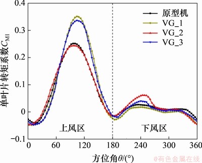
图8 不同方案下单叶片转矩系数
Fig. 8 Blade torque coefficient under different schemes
由图8可知:叶片加装VG前后叶片转矩系数产生了一定的变化。在上风区,VG_2方案叶片转矩系数与原型机的基本保持一致。当方位角θ<80°时,VG_1方案和VG_3方案叶片转矩系数反而比原型机的低;当方位角θ在80°~180°范围内变化时,VG_1方案和VG_3方案叶片转矩系数整体比原型机的高,其拐点在相比原型机有一定相位的延迟,但其中VG_1方案单叶片最大转矩系数CMl,max比原型机的提高35%左右,VG_3方案叶片最大转矩系数略比VG_1方案的低。在下风区垂直轴风力机叶片转矩系数呈现出波动变化,VG_1方案对应的叶片转矩系数整体都处于最低水平。当方位角θ在180°~260°范围内变化时,VG_2方案和VG_3方案叶片转矩系数均比原型机的高,但VG_3方案叶片最大转矩系数略比VG_2方案的低。从整体上看,VG_1方案和VG_3方案主要在上风区对叶片转矩系数起到明显的提升效果,而VG_2方案在下风区对叶片转矩系数有所改善。表4所示为不同方案下垂直轴风力机单叶片平均转矩系数CMl,ave及提升效果情况。
表4 不同方案下单叶片转矩系数及提升效果
Table 4 Torque coefficient and lifting effect of blade under different schemes
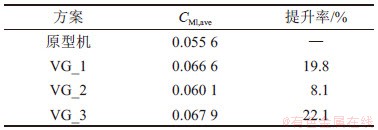
由表4可以看出:VG_1方案和VG_3方案对叶片转矩系数有较明显的改善效果,其中VG_3方案提升效果最佳,提升率比VG_1方案的提升率高2.3%;而VG_2方案提升率最低,仅为8.1%。
3.2 3种方案对整机风能利用率提升效果分析
上述是分析的VAWT单叶片转矩系数,为了进一步获得VAWT整体性能,通过在FLUENT中监测的两叶片扭矩系数,得到整机转矩系数CM随方位角变化曲线如图9所示。
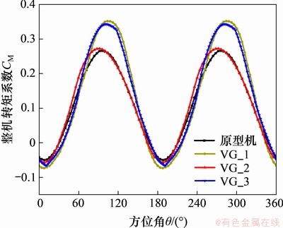
图9 不同方案下整机转矩系数随方位角的变化曲线
Fig. 9 Variation curve of torque coefficient with azimuth under different schemes
根据整机平均转矩系数CM, ave,可由式(2)和(3)计算得到垂直轴风力机驱动力矩M和风能利用率CP:
 (2)
(2)
 (3)
(3)
式中:ρ为空气密度(kg/m3);v为来流风速(m/s);A为扫掠面积(m2);L为特征长度(m),其值为叶片弦长c;H为风机高度(m);ω为旋转角速度(rad/s)。
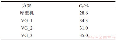
计算得到不同方案下垂直轴风力机整机的风能利用率,如表5所示。从表5可以看出:VG_3方案对垂直轴风力机风能利用率提升效果最佳,相比原型机的提高了6.4%,VG_1方案的提升效果也比较好,VG_2方案提升效果最差,仅提高了2.4%。
表5 不同方案下整机风能利用率
Table 5 Utilization ratio of whole machine under different schemes
3.3 加装VG对叶片周围流场的影响
根据3.1节的研究结果,可以发现在下风区VG_2方案和VG_3方案对风力机转矩系数提升效果不明显,而在上风区,VG_1方案和VG_2方案对风力机转矩系数提升效果比较明显,从而导致VG_2方案对垂直轴风力机整机风力利用率CP提升效果较差。为了进一步分析叶片不同表面加装VG对其周围流场的影响情况,利用CFD-POST后处理软件,选取叶片展向中位面为观察截面,对3.1节中不同方案下叶片周围流场进行考察。
在上风区,VG_2方案对叶片转矩系数几乎没有影响,VG_1方案和VG_3方案在80°~150°方位角范围内对叶片转矩系数有明显提升。表6所示为上风区风力机叶片表面在不同方位角下的流线图。
由表6可以看出:在上风区,原型机叶片表面后缘的位置从方位角70°开始出现小失速涡,随着叶片的旋转,失速涡逐渐变大并向前缘扩散,而由于VG_1方案和VG_3方案中叶片内表面装有VG,当气体粒子经过VG时在VG的尾部产生漩涡,漩涡将附面层外部动能较高的流体带入附面层内,从而增加了附面层内流体的动能;叶片内表面加装VG明显延迟了失速涡的产生,并且阻碍了失速涡的发展,使叶片失速所处的方位角范围极大地减小。结合图9中3种不同方案下叶片转矩系数曲线还可以发现:正是叶片内表面加装VG延迟了失速的产生并抑制了失速的发展,使VG_1方案和VG_3方案叶片转矩系数得到极大提升,进而提高了垂直轴风力机的气动性能。
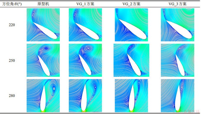
在下风区,VG_1方案对应叶片转矩系数相比原型机有所下降,VG_2方案和VG_3方案在210°~280°方位角范围内对叶片转矩系数有明显提升。表7所示为下风区风力机叶片表面在不同方位角下的流线图。
由表7可以看出:在下风区,原型机叶片表面后缘的位置从方位角为220°出现失速涡,而VG_2方案和VG_3方案叶片外表面加装VG,阻碍了失速涡的发展,但2种方案在220°方位角处开始出现小失速涡,并且随着叶片的旋转,失速涡逐渐变大并向前缘扩散,可见叶片外表面加装VG在下风区的效果明显不如上风区,对叶片转矩系数的提升效果不明显,这是由于来流风经过上风区后使得流场变得复杂紊乱,改变了来流风的速度和方向,导致下风区叶片外表面加装VG效果变差。
表6 上风区风力机叶片表面在不同方位角下的流线图
Table 6 Streamline diagram of wind turbine blade surface at different azimuths in upwind area
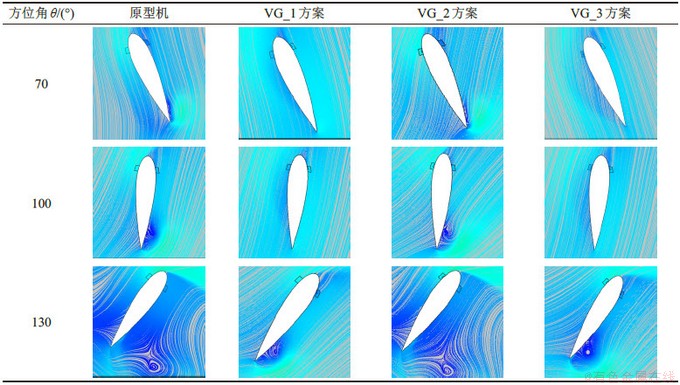
表7 下风区风力机叶片表面在不同方位角下的流线图
Table 7 Streamline diagram of wind turbine blade surface at different azimuths in downwind area
综上所述,基于本文风力机模型和所选VG模型,VG布置弦向位置为10%c处,在叶片内外表面或叶片内表面加装VG对VAWT风能利用率提升效果较大,考虑到VG制造成本和安装、维修等因素,方案选择时可在叶片内外表面或叶片内表面加装VG选其一。
4 结论
1) 针对H型VAWT风能利用率低的问题,提出了3种在叶片表面加装VG的方案:分别在叶片内表面、外表面和内外表面安装VG。对风力机整机建立了仿真模型并进行了网格独立性和准确性验证,得到最佳网格数目为4.3×10⁶个。
2) 上风区内表面和下风区外表面加装涡流发生器均可提高叶片的转矩系数,上风区吸力面加装VG对转矩系数的提升效果明显比下风区吸力面加装VG的优。3种不同VG布置方案中,叶片内外表面加装VG时垂直轴风力机风能利用率CP提升效果最好,与原型风力机的相比CP提升6.4%。
3) 在上风区吸力面加装VG延迟了失速的产生并抑制了失速的发展,但来流风经过上风区后使得流场变得复杂紊乱,使得下风区吸力面加装VG作用效果变差。
参考文献:
[1] 李岩. 垂直轴风力机技术讲座(1)垂直轴风力机及其发展概况[J]. 可再生能源, 2009, 27(1): 121-123.
LI Yan. Vertical axis wind turbine technology lecture(1): vertical axis wind turbine and its development[J]. Renewable Energy Resources, 2009, 27(1): 121-123.
[2] GBADEBO S A, CUMPSTY N A, HYNES T P. Three-dimensional separations in axial compressors[J]. Journal of Turbomachinery, 2005, 127(2): 331-339.
[3] GUNTUR S, SORENSEN N N, SCHRECK S, et al. Modeling dynamic stall on wind turbine blades under rotationally augmented flow fields[J]. Wind Energy, 2016, 19(3): 383-397.
[4] XU Heyong, QIAO Chenliang, YANG Huiqiang, et al. Delayed detached eddy simulation of the wind turbine airfoil S809 for angles of attack up to 90 degrees[J]. Energy, 2017, 118: 1090-1109.
[5] 伊恩・帕拉斯基沃尤. 垂直轴风力机原理与设计[M]. 李春, 叶舟, 高伟, 译. 上海: 上海科学技术出版社, 2013:55-60.
PARASCHIVOIU I. Principle and design of vertical axis wind turbine[M]. LI Chun, YE Zhou, GAO Wei, trans. Shanghai: Shanghai Science and Technology Press, 2013: 55-60.
[6] 田海姣, 王铁龙, 王颖. 垂直轴风力发电机发展概述[J]. 应用能源技术, 2006(11): 22-27.
TIAN Haijiao, WANG Tielong, WANG Ying. Summarize of the development of the vertical-axis wind turbine[J]. Applied Energy Technology, 2006(11): 22-27.
[7] CHEHOURI A, YOUNES R, ILINCA A, et al. Review of performance optimization techniques applied to wind turbines[J]. Applied Energy, 2015, 142: 361-388.
[8] MOHAMED M H. Performance investigation of H-rotor Darrieus turbine with new airfoil shapes[J]. Energy, 2012, 47(1): 522-530.
[9] RAMADAN A, YOUSEF K, SAID M, et al. Shape optimization and experimental validation of a drag vertical axis wind turbine[J]. Energy, 2018, 151: 839-853.
[10] EBRAHIMI A, MOVAHHEDI M. Wind turbine power improvement utilizing passive flow control with microtab[J]. Energy, 2018, 150: 575-582.
[11] TAYLOR H D. The elimination of diffuser separation by vortex generators[R]. East Hartford, USA: United Aircraft Corporation Report, 1947: 4012-4014.
[12] TIMMER W A, VAN ROOIJ R P J O M . Summary of the delft university wind turbine dedicated airfoils[J]. Journal of Solar Energy Engineering, 2003, 125(4): 488-496.
[13] ALLAN B, YAO C S, LIN J. Numerical simulations of vortex generator vanes and jets on a flat plate[C]// 1st Flow Control Conference. St. Louis, Missouri. Reston, Virigina: AIAA, 2002: 1-14.
[14] KHALFALLAH M G, KOLIUB A M. Suggestions for improving wind turbines power curves[J]. Desalination, 2007, 209(1/2/3): 221-229.
[15] 倪亚琴. 涡流发生器研制及其对边界层的影响研究[J]. 空气动力学学报, 1995, 13(1): 110-116.
NI Yaqin. Development of the vortex-generator and study on the effect of vortex-generator on boundary layer[J]. Acta Aerodynamica Sinica, 1995, 13(1): 110-116.
[16] 张立军, 朱怀宝, 顾嘉伟, 等. 涡流发生器对垂直轴风力机翼型气动性能的影响[J]. 中南大学学报(自然科学版), 2020, 51(2): 540-550.
ZHANG Lijun, ZHU Huaibao, GU Jiawei, et al. Influence of vortex generator on aerodynamic performance of airfoil the of vertical axis wind turbine[J]. Journal of Central South University(Science and Technology), 2020, 51(2): 540-550.
[17] LI Qingan, MAEDA T, KAMADA Y, et al. The influence of flow field and aerodynamic forces on a straight-bladed vertical axis wind turbine[J]. Energy, 2016, 111: 260-271.
[18] 刘光远, 贾智亮, 陈学孔, 等. 基于涡流发生器的风洞试验段附面层控制数值模拟[J]. 气体物理, 2018, 3(3): 34-40.
LIU Guangyuan, JIA Zhiliang, CHEN Xuekong, et al. Numerical simulation of boundary layer control in wind tunnel test section based on eddy current generator[J]. Gas Physics, 2018, 3(3) :34-40.
[19] 叶叶沛. 涡流发生器原理和设计[J]. 西飞科技, 1996(2): 2-5.
YE Yepei. Mechanism and design of vortex generators[J]. Xifei Technology, 1996(2): 2-5.
[20] PAIBOOLSIRICHIT T. 3D simulation of wing fitted with Vortex Generators[C]// 2016 Second Asian Conference on Defence Technology (ACDT). Chiang Mai, Thailand: IEEE, 2016: 73-77.
[21] 张立军, 赵昕辉, 王旱祥,等. H型垂直轴风力机实时高效攻角调节方法研究[J]. 机械工程学报, 2018, 54(10): 173-181.
ZHANG Lijun, ZHAO Xinhui, WANG Hanxiang, et al. Research on real-time high-efficiency angle of attack adjustment method for H-type vertical axis wind turbine[J]. Journal of Mechanical Engineering, 2018, 54(10): 173-181.
[22] 张立军, 赵昕辉, 马东辰,等. 垂直轴风轮阻力型支撑杆研究[J]. 中国机械工程, 2017, 28(12): 1449-1455.
ZHANG Lijun, ZHAO Xinhui, MA Dongchen, et al. Research on vertical shaft wind turbine resistance type support rod[J]. China Mechanical Engineering, 2017, 28(12): 1449-1455.
[23] 惠万馨, 顾煜炯, 刘莎莎, 等. 垂直轴风力机三维气动性能的数值模拟及分析[J]. 现代电力, 2013, 30(1): 85-89.
HUI Wanxin, GU Yujiong, LIU Shasha, et al. Numerical simulation and analysis of three-dimensional pneumatic performance of vertical axis wind turbine[J]. Modern Electric Power, 2013, 30(1): 85-89.
[24] 王巧红, 张洛明, 李博, 等. 小型垂直轴风力发电机风轮流场的三维数值模拟[J]. 机械设计与制造, 2010(4): 216-218.
WANG Qiaohong, ZAHNG Luoming, LI Bo, et al. Three-dimensional numerical simulation of wind rotation field of small vertical axis wind turbine[J]. Mechanical Design and Manufacture, 2010(4): 216-218.
[25] 张磊, 杨科, 黄宸武, 等. 基于数值模型的涡流发生器参数设计[J]. 工程热物理学报, 2012, 33(12): 2084-2087.
ZHANG Lei, YANG Ke, HUANG Chenwu, et al. Parameters design of vortex generators based on numerical models[J]. Journal of Engineering Thermophysics, 2012, 33(12): 2084-2087.
[26] PIPERAS A T. Investigation of boundary layer suction on a wind turbine airfoil using CFD[D]. Kongens Lyngby: Technical University of Denmark, 2010: 18-23.
[27] SAGHARICHI A, MAGHREBI M J, ARABGOLARCHEH A. Variable pitch blades: an approach for improving performance of Darrieus wind turbine[J]. Journal of Renewable and Sustainable Energy, 2016, 8(5): 053305.
[28] ORLANDI A, COLLU M, ZANFORLIN S, et al. 3D URANS analysis of a vertical axis wind turbine in skewed flows[J]. Journal of Wind Engineering and Industrial Aerodynamics, 2015, 147: 77-84.
(编辑 杨幼平)
收稿日期: 2019 -09 -12; 修回日期: 2020 -05 -01
基金项目(Foundation item):国家自然科学基金资助项目(51707204);中央高校基本科研业务专项资助项目(17CX05021) (Project(51707204) supported by the National Natural Science Foundation of China; Project(17CX05021) supported by the Fundamental Research Funds for the Central Universities)
通信作者:张立军,博士,教授,硕士生导师,从事可再生能源技术和绿色装备制造研究;E-mail:zlj-2@163.com

