Design of motion control system of pipeline detection AUV
来源期刊:中南大学学报(英文版)2017年第3期
论文作者:孙玉山 姜春萌 万磊
文章页码:637 - 646
Key words:pipeline detection autonomous underwater vehicle (PDAUV); novel neural network-based control; motion control system; embedded system architecture; system identification
Abstract: A great number of pipelines in China are in unsatisfactory condition and faced with problems of corrosion and cracking, but there are very few approaches for underwater pipeline detection. Pipeline detection autonomous underwater vehicle (PDAUV) is hereby designed to solve these problems when working with advanced optical, acoustical and electrical sensors for underwater pipeline detection. PDAUV is a test bed that not only examines the logical rationality of the program, effectiveness of the hardware architecture, accuracy of the software interface protocol as well as the reliability and stability of the control system but also verifies the effectiveness of the control system in tank experiments and sea trials. The motion control system of PDAUV, including both the hardware and software architectures, is introduced in this work. The software module and information flow of the motion control system of PDAUV and a novel neural network-based control (NNC) are also covered. Besides, a real-time identification method based on neural network is used to realize system identification. The tank experiments and sea trials are carried out to verify the feasibility and capability of PDAUV control system to complete underwater pipeline detection task.
Cite this article as: JIANG Chun-meng, WAN Lei, SUN Yu-shan. Design of motion control system of pipeline detection AUV [J]. Journal of Central South University, 2017, 24(3): 637-646. DOI: 10.1007/s11771-017-3464-2.
J. Cent. South Univ. (2017) 24: 637-646
DOI: 10.1007/s11771-017-3464-2

JIANG Chun-meng(姜春萌), WAN Lei(万磊), SUN Yu-shan(孙玉山)
Science and Technology on Underwater Vehicle Laboratory, Harbin Engineering University, Harbin 150001, China
 Central South University Press and Springer-Verlag Berlin Heidelberg 2017
Abstract: A great number of pipelines in China are in unsatisfactory condition and faced with problems of corrosion and cracking, but there are very few approaches for underwater pipeline detection. Pipeline detection autonomous underwater vehicle (PDAUV) is hereby designed to solve these problems when working with advanced optical, acoustical and electrical sensors for underwater pipeline detection. PDAUV is a test bed that not only examines the logical rationality of the program, effectiveness of the hardware architecture, accuracy of the software interface protocol as well as the reliability and stability of the control system but also verifies the effectiveness of the control system in tank experiments and sea trials. The motion control system of PDAUV, including both the hardware and software architectures, is introduced in this work. The software module and information flow of the motion control system of PDAUV and a novel neural network-based control (NNC) are also covered. Besides, a real-time identification method based on neural network is used to realize system identification. The tank experiments and sea trials are carried out to verify the feasibility and capability of PDAUV control system to complete underwater pipeline detection task.
Key words: pipeline detection autonomous underwater vehicle (PDAUV); novel neural network-based control; motion control system; embedded system architecture; system identification
1 Introduction
Offshore oil and gas pipeline transpiration is of vital strategic significance to the national economy [1], of which safety and reliability are the precondition [2]. Accidents to pipeline will not only result in huge economic losses [3] but also produce severe consequences on the environment [4].
In recent years, underwater pipelines in China have suffered from cracking [5] and leakage [6] problems in their long-time service as the result of corrosion in and outside [7]. The economic losses caused by pipeline leakage have amounted to billions each year [8]. For this reason, underwater pipeline detection is of great importance and should be paid high attention from the standpoint of economic development and environmental protection [9].
The conventional underwater pipeline detection is done by divers with special equipment [10], which is of low efficiency and great danger [11]. For this reason, Remotely operated vehicle (ROV) is used for pipeline detection over one-hundred-meter underwater [12]. However, it must work with a mother ship, which is not only very expensive but also suffers from intertwined umbilical cables [13].
With the rapid development of artificial intelligence [14], automatic control [15], computer network [16] and simulation [17], the autonomous underwater vehicle (AUV) technology has made great progress [18]. Today, AUV has received increasingly widespread application in fields such as subsea resource development, underwater topography, hydrological information acquisition, dam and pipeline detection as well as relay communication [19]. The pipeline detection AUV (PDAUV) is developed by Science and Technology on Underwater Vehicle Laboratory, Harbin Engineering University, China for the detection of corrosion, crack and any other potential problem of pipeline. The PDAUV is typically in a streamline spheroid shape and equipped with a number of advanced sensors for detection and acquisition. As the carrier of detection sensors, the movement of PDAUV must work effectively and stably to meet the requirements of underwater pipeline detection.
In this work, the design of motion control system of PDAUV is proposed. The architecture of the AUV motion control system is also introduced, including both hardware and software architectures. System identification based on neural network is adopted to establish the six-DOF simulation system of the AUV. The feasibility and validity of the motion control system of PDAUV are verified by tank experiments and sea trials, with the algorithms also well proved.
2 PDAUV platform
The PDAUV is a test platform for the study of motion control, object detection, path planning, etc. AUV includes many systems, such as motion control system, navigation system, power system, path planning system, vision system and emergency handling system. As shown in Fig. 1, the PDAUV has the following characteristic parameters, namely dimensions of 5.5 m×1.0 m×1.0 m (L×W×H), dry mass of 2.5 t, maximum velocity of 2.0 m/s and max diving depth of 300 m. The AUV is composed of eight thrusters. Four ducted thrusters serve as the main thrusters, two thrusters serve as the horizontal main thrusters and another two thrusters serve as the vertical main thrusters. In addition, four conduit thrusters function as the lateral thrusters and the vertical thrusters. The AUV works with several sensors, including Doppler velocity logger (DVL), gyrocompass, depth logger, altimeter, video camera and image sonar to complete different tasks.
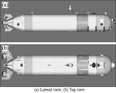
Fig. 1 Configuration of PDAUV:
3 PDAUV motion control system
Information is acquired by the PDAUV’s control system by way of sensors for analysis, evaluation and processing. The system first produces control commands from the control algorithm and then sends the commands to the thrusters via networks so that all devices work in coordination and the AUV operates with expectation.
The motion control computer established upon PC/104-bus and real-time operating system VxWorks is vital to the motion control system of PDAUV. PC/104 is a commonly-used bus [20] while VxWorks was developed by WindRiver [21] for embedded system.
The control system of PDAUV includes an embedded industrial personal computer (IPC)[22] that is made of several boards with independent functions. Installed inside the AUV for the purpose of reliability and stability, the IPC communicates with the sensors and actuators to acquire data and send thrust commands.
The PC/104-bus IPC is adopted by the AUV, on which the real-time embedded operating system VxWorks works to achieve autonomous control. The IPC is connected with gyrocompass, depth logger, altimeter, DVL, inertia navigation system (INS) and DC brushless thrusters to realize real-time data acquisition and command sending. The configuration of PDAUV’s control system is shown in Fig. 2.

Fig. 2 System configuration of PDAUV
3.1 Hardware architecture of PDAUV
Analyses have proved that the control system of PDAUV can execute functions including data acquisition and processing, control algorithm, thrust allocation, command sending, receiving attitude angle from gyrocompass, velocity from DVL and altitude from altimeter by means of serial board, collecting depth and leakage data through A/D board, getting target commands from planning and navigation systems based on UDP and TCP, and sending analogue voltage to thrusters through D/A board. The hardware architecture of PDAUV motion control system is shown in Fig. 3.
PC/104-bus-based multi-board embedded system is adopted for the AUV to achieve motion control. The boards coordinate with each other when overlaid in layers. The system is composed of CPU board, serial board, A/D board, D/A board and power board. Acting as the heart of the whole embedded system, the CPU board uses Intel Pentium M processor and INTEL85XGME chip array with 1.0 GHz master frequency. The serial board selects MSP-12 developed by SBS which integrates a 16-byte first-in-first-out (FIFO) buffer andallows base address sharing and interrupt sharing. The A/D board uses ADT882-AT developed by SBS with 16-bit resolution and a maximum sample rate of 200 kHz. The D/A board adopts RUBY-MM developed by Diamond System with 12-bit resolution and adjustable base address and interrupt level. JMM-512 developed by Diamond System is used as the power board to provide 5V and 12V output.

Fig. 3 Hardware architecture of PDAUV motion control system
3.2 Software architecture of PDAUV
3.2.1 Control software architecture
As far as the IPC is concerned, C programming language is chosen to develop programs of high efficiency and portability [23]. The module design allows quick modification and on-line debugging. Sensor information acquisition, data preprocessing, data fusion, control algorithm, thrust allocation, command sending and communication serve as the main modules in the control software architecture.
As shown in Fig. 4, the information flow of the motion control system consists of four sections. Section I is the data processing module which includes data preprocessing and data fusion. Invalid data rejection and linear smoothing are done in data preprocessing, after which data fusion is performed. Data fusion improves data fault-tolerant ability and accuracy. This module provides high-precision data for the control algorithm. Section II is the control algorithm module in which control methods are used to acquire expected thrust and achieve motion control over the AUV. In Section III, the thrust allocation module conducts thrust allocation algorithm. In the meantime, it sends force commands to thrusters. Section IV is the hardware architecture. Playing the most important part in the motion control system, it contains thrusters and sensors. Thrusters provide forces while sensors acquire data of the AUV.

Fig. 4 Information flow of motion control system
3.2.2 Motion control algorithm
There have been studies on control algorithms in recent years [24-26]. Each has their advantages and limitations [27]. The algorithm is designed in accordance with the characteristics and tasks of the controlled member.
In view of the distinct nonlinear and coupling characteristics of the AUV, fuzzy control and neural network control are adopted as the main control methods. As the PDAUV requires different devices to complete tasks, it is difficult to construct the precise system model. A novel neural network-based control (NNC) method is introduced to achieve reliable control on the basis of systematic study. As shown in Fig. 5, it is made up of three parts, namely expected-state planner, self-learning part (including self-learning control network and identification network) and on-line part (including on- line control network and identification network). With the introduction of the expected-state planner and self- learning part, it is different from common neural network methods in structure and algorithm.
As shown in Fig. 5, the novel NNC includes several neural networks such as on-line control network, self-learning control network, on-line identification network and self-learning identification network. The interactive relation among the networks is obvious. The control networks follow the structure shown in Fig. 6 to achieve real-time and effective control. The recursive structure in Fig. 7 is adopted by the identificationnetworks to acquire dynamic information and improve information transmission among the neurons. In the self-learning control network, the bias between reference signals r(k) and state variables is the input while the outcome from the expected-state planner is the expected output. The bias between reference signals r(t) and state variables is the input to the on-line control network. The input to the on-line identification network is the output of the on-line control network u(t) and state variables several steps before. The expected output of the on-line identification network is state variables. The identification network and control network work independently, but they can be updated synchronously at all control steps. The identification networks, well- trained in the self-learning part, can work as a controlled model that produces samples a few steps before the present state for reference. Therefore, the control algorithm in the self-learning part will be well adjusted. In this way, the control algorithm is improved in performance and the controlled plant is under well control.
In the control and identification networks, the ith neuron at the (n+1)th layer is processed as follows.
 (1)
(1)
where  is the synaptic weight of neuron i at layer n+1 fed from neuron j at layer n;
  represents the bias applied to the neuron i at layer and
  stands for the output of neuron j at layer n+1. Function ψ(x) comes from input layer:
 (2)
(2)
and hidden layer & output layer:
 (3)
(3)
Because of the complex network topology of this NNC, a new learning algorithm, therefore, is proposed. In this algorithm, the adjustable weights are updated with the control and identification networks taken as a 6-layer network (as shown in Fig. 8) to be trained. In the present work, the real-time performance and effectiveness of the control system can be ensured with only four of the six layers updated with the weights.
To obtain weight adjustment formula, the output errors follow evaluation function E:
 (4)
(4)
where di is the expected output of the ith neuron and oi is the actual output. Adjustment is made to each with  for the minimum E in following equation:
 (5)
(5)
where  is the weight variation in the (t+1)th control step;
  is the weight variation in the tth control step; β stands for the learning rate of the neural network and λ represents the momentum factor.
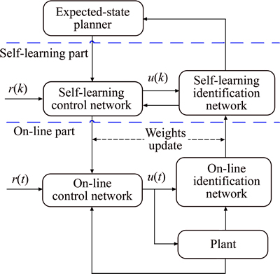
Fig. 5 Structure of NNC

Fig. 6 Structure of control network
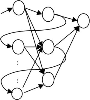
Fig. 7 Structure of identification network
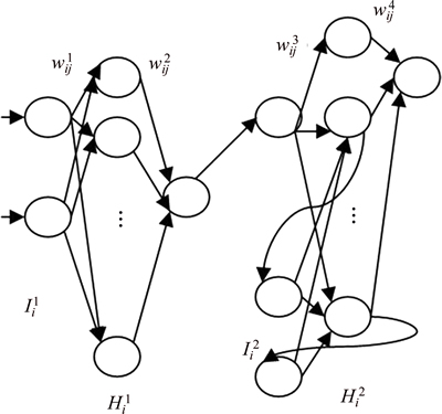
Fig. 8 Six-layer neural network to be trained
 and
and  are assumed to be the ith neuron at the first and second input layer respectively;
  and
and  are the ith neurons at the first and second hidden layers, respectively. ui is the ith neuron at the first output layer. As a result, the updating algorithm is as follows:
 (6)
(6)
 (7)
(7)

 (8)
(8)
 (9)
(9)
 (10)
(10)
The weights of the identification network can be updated separately based on Eqs. (6) and (7). As illustrated in Eqs. (8)-(10), the weights of the control network must synchronize with that of the identification network. This means that the performance of the control algorithm is determined by the identification network. With this regard, a high performance is important to the identification network. The identification results, which will be mentioned later, prove that the identification network can meet our expectations.
BP algorithm is known as a classic, but it only fits for single-layered network. It is always argued for its slow learning, which makes it unfit for online learning and real-time control [28]. This is true to some extent. The total bias convergence of the network is tardy and when batch learning is adopted, it is very likely to lead to local minimum. Therefore, in order to realize global optimum solution, an expected-state planner is designed to keep the output bias at a low level so that the control system can operate reliably.
An expected-state planner is used in the novel NNC method to obtain the desired acceleration which is expected to guide network weight adjustment. The desired acceleration is designed as
 (11)
(11)
where amax is the maximal acceleration of the AUV. It reflects the net weight of the AUV and power of the thrusters, and it varies with the thrusters equipped. P is defined as
 (12)
(12)
in which pi comes from
 (13)
(13)
where ki1 and ki2 are to be determined. They are parameters requiring manual or automatic adjustment. ei and  are defined as
 (14)
(14)
 (15)
(15)
where i represents degree of freedom; si is the bias between the target and present position, which suggests the preliminary performance of position control. Influenced by the thrusters, simax is the predetermined maximum distance based on the ability of the AUV, and it varies with the thrusters equipped.
4 System identification of PDAUV
In accordance with years of study and research, a variety of simplified models have been developed for AUV control [29]. The AUV moves in accordance with the following equation given to its movement characteristics such as relative slowness, seldom drastic change in position and attitude, high nonlinearity and the existence of three symmetry planes.
 (16)
(16)
where Ft represents the force or moment provided by the thrusters; Fs stands for the force or moment from the static loads (gravity and buoyancy) in the body-fixed frame; A and Iv are damping and inertial force matrixes respectively. The Taylor series or empirical formulas provide the damping force while inertial hydrodynamic coefficients come from hydrodynamic test. M is the mass matrix with added mass included.  is the velocity vector of body-fixed frame in which u, v and w are linear velocities in directions of surge, sway and heave while p, q and r are angular velocities in directions of roll, pitch and yaw. Iv and M follow:
 (17)
(17)

 (18)
(18)
where 
 and
and  are hydrodynamic coefficients determined by hydrodynamic test; m is the mass of the model. The coupling effects are taken as the uncertainties for the purpose of decoupling. Therefore, the acceleration is assumed to the function of the velocity and thrust in their direction.
The foresaid identification network is used to identify the movement characteristics of the AUV. Different typical response tests are usually carried out to acquire the sample data. In the present work, the indicial response of the AUV is measured to obtain the sample. A three-layer structure is adopted in the identification network. The input layer includes 10 neurons, two of which represent velocity and force determined by the thrusters and the other eight are the feedbacks from hidden neurons. The hidden layer includes 8 neurons. The acceleration in the direction is the output. The evaluation function is given as
 (19)
(19)
where aid is the acceleration learned by the identification network; ad is the expected acceleration and the actual acceleration as well.
The top priority is given to the motion in directions of surge, sway, heave and yaw due to the obvious traits of pipeline detection task. System identification in these four directions is made. The input force or moment provided by the thrusters is changed to produce data to train the identification network. Verification samples are also obtained to evaluate the learning effect of the identification network. The indicial response test provides the identification results in the heave direction in Fig. 9. The solid line reflects the output of the neural network while the dotted line suggests the actual acceleration of controlled plant. It can be inferred from the results that the identification network that learns well can effectively reflect the characteristics of the controlled plant and produce better identification effects so as to provide practical reference to the control network.

Fig. 9 Identification result of heaving motion
The above method is conducted for off-line training. Equations (6) and (7) are adopted by the identification network only for training. The on-line identification network is trained online to improve the identification results, with the weights simultaneously transferred to the self-learning identification network to train the self- learning control network.
5 PDAUV control
With the expected acceleration given by the expected-state planner as the sample, the control network is trained with Eqs. (8)-(10). The control network also follows a three-layer structure, with 2 neurons at the input layer, 6 neurons at the hidden layer and 1 neuron at the output layer. As stated in Eqs. (14) and (15), the inputs are ei (bias of the DOF) and  (change rate of bias) while the output is the force applied to the AUV body. The self-learning control network can be trained online based on the algorithm introduced above. It is noted that the input to the self-learning control network can be obtained from the self-learning identification network. For this reason, the self-learning control network can be well trained with the output from the self-learning identification network. Thus, it guarantees reliable control and keeps the control system at work.
The whole process of neural network learning and control can be summarized as follows. To begin with, the self-learning identification network is trained offline to obtain prior information of the controlled plant as the preliminary knowledge. The online training starts then. The self-learning control network is well trained with the trained self-learning identification network and expected acceleration. When the training completes, the self- learning control network transfers its adjusted weights to the on-line control network for the purpose of synchronized weights in the control network. Then, the output of the on-line control network is used to work out the thrust of all thrusters. At this point, the on-line identification network learns and transfers its weights to the self-learning network after being well trained. This method improves the learning speed of the whole system by weight updating among the networks and keeps the plant well under control based on the identification network.
6 Experiment results and discussion
The development of AUV of any type goes through project design, technical design, construction design and experimental verification. Experimental verification typically includes numerical simulation, tank experiment, and lake or sea trial. Staged verification not only conforms to the law of scientific development but also prevents the risk in development, and the results of lake or sea trial are the basis for the acceptance of the AUV project.
To verify the effectiveness of the method proposed, the hardware and logical rationality of software of the control system are examined on the simulation platform. Simulation experiments are carried out to adjust network weights and relevant control parameters. The tank experiments and sea trials are also conducted. Limited by the actual data output rate of the AUV, the controller runs at 2 Hz in tank experiments and sea trials.
6.1 Results of numerical simulation
The position control results in surge, sway, heave and yaw with 0.3 m/s current of 0° are shown in Fig. 10. {0, 0, 1, 0} is the initial position and {5, 2, 3, 20} is the target position. The control results can be seen in Fig. 10. As the results suggest, the control effect is good, which reflects the rationality of software and hardware logic.
6.2 Results of tank experiments
The tank experiment is carried out at Harbin Engineering University, China in a deep-pool with the dimensions of 50 m×30 m×10 m (L×B×H). The deep pool is shown in Fig. 11.
The 0.5 m and 2.3 m depth tests in still water are carried out, whose result is shown in Fig. 12. As the results show, the overshoot of the depth position control is very small, with a stable error of ±0.1 m. Therefore, the controller with the proposed control method performs well in the tank experiments.


Fig. 10 Simulation result of position control:

Fig. 11 Deep pool for tank experiments

Fig. 12 Results of depth control in deep-pool
6.3 Results of sea trials
To examine the performance of the PDAUV, the sea trial is carried out in Shandong Province, China. The test includes position control, velocity control, target detection, pipeline detection and long-distance navigation. The trial area condition is shown in Fig. 13. Firstly, the debugging of the controller is conducted so that the controller learns the environment of the trial area. Then the position and velocity control experiments are carried out to test the performance of the controller, which is the foundation for the other tasks. Thirdly, target detection and pipeline detection are carried out, followed by long-distance navigation at last.
The position tracking results are shown in Fig. 14. The dotted line stands for the target position and attitude.
As the results show, position tracking is well realized on the PDAUV with high precision. The test results are quite gratifying considering the marine conditions with a deviation of 0.30 m in the north and east, depth deviation of 0.5 m and yaw angle deviation of 1.0°.
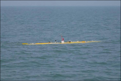
Fig. 13 Experiment area for sea trial

Fig. 14 Results of position tracking control:
The results of velocity control are shown in Fig. 15. The dotted line is the target value. The test is not very long, but the control system works steadily. It can be seen from the results that the velocity control is steady, with a depth deviation of 0.35 m and yaw deviation of 1.5°. The deviations are slightly bigger than that of the position tracking control. It is because the higher surge velocity results in obvious coupling effect among the degrees of freedom of the PDAUV. Nevertheless, such control precision can satisfy the requirements of engineering tasks.

Fig. 15 Results of velocity control:
7 Conclusions
1) The motion control system architecture of PDAUV is constructed, including both the hardware and software architectures. Multiple-board embedded system is adopted with the boards overlaid with each other to realize data acquisition, data preprocessing and fusion, control algorithm and real-time communication with peripherals. Modular design is adopted in the software architecture for the purpose of high efficiency and portability in software development.
2) The novel neural network-based control method is put forward for AUV motion control. It is made up of expected-state planner, self-learning part and on-line part. The introduction of the expected-state planner and self-learning part allows minor network output bias and keeps the control plant well under control.
3) Tank experiments and sea trials are carried out to verify the effectiveness of the design. As the results indicate, the PDAUV provides high control accuracy. Safe and reliable, the control system can well perform motion control in underwater pipeline detection.
References
[1] PATRIZIA V, GIUSEPPE G, ROSARIO M. Pipeline flow measurement using real-time imaging [J]. Journal of Measurement, 2014, 47: 1008-1015.
[2] KIM D, CHOI H S, KIM J Y. Trajectory generation and sliding-mode controller design of an underwater vehicle-manipulator system with redundancy [J]. International Journal of Precision Engineering and Manufacturing, 2015, 16(7): 1561-1570.
[3] HOSSEIN N E, VAHID A, MOHAMMAD D. A time delay controller included terminal sliding mode and fuzzy gain tuning for underwater vehicle-manipulator system [J]. Ocean Engineering, 2015, 107: 97-107.
[4] TRAN N H, CHOI H S, BAE J H. Design, control and implementation of a new AUV platform with a mass shifter mechanism [J]. International Journal of Precision Engineering and Manufacturing, 2015, 16(7): 1599-1608.
[5] CRAMER R, SHAW D, TULALIAN R, ANGELO P. Detecting and correcting pipeline leaks before they become a big problem [J]. Marine Technology Society Journal, 2015, 49(1): 31-46.
[6] CHIN C S, LAU M W S. Supervisory cascaded controller design: Experiment test on a remotely operated vehicle [J]. Journal of Mechanical Engineering Science, 2011, 225(3): 584-602.
[7] FANISULAINMA M, ABSULLAH F, JALI M. A feasibility study of internal and external based system for pipeline leak detection in upstream petroleum industry [J]. Australian Journal of Basic & Applied Sciences, 2014, 8(3): 204-211.
[8] MOHAMMAD H K, SAEED B. Modeling and control of autonomous underwater vehicle(AUV) in heading and depth attitude via self-adaptive fuzzy PID [J]. Journal of Marine Science and Technology, 2015, 20: 559-578.
[9] KIM D W. Tracking of REMUS autonomous underwater vehicles with actuator saturations [J]. Automatic, 2015, 58: 15-21.
[10] XI Bin, CHEN Jie, PENG Zhi-hong. Intelligent optimized control: Overview and prospect [J]. Acta Automatica Sinica, 2013, 39(11): 1831-1834. (in Chinese)
[11] MEENAKSHI S, SAMBHUNATH N, SANKAR N S. Energy efficient trajectory tracking controller for underwater applications: A robust approach [J]. Aquatic Procedia, 2015, 4: 571-578.
[12] WALLACE M B, MAX S D, EDWIN K. An adaptive fuzzy sliding mode controller for remotely operated underwater vehicles [J]. Robotics and Autonomous Systems, 2010, 58: 16-26.
[13] AZIS F A, ARAS M S M, RASHID M Z A. Problem identification for underwater remotely operated vehicle(ROV): A case study [J]. International Journal of Control, Engineering Procedia, 2012, 4: 554-560.
[14] MAURIZIO P, GARY R, DANIEL J S. Tracking and formation control of multiple autonomous agents: A two-level consensus approach [J]. Automatic, 2007, 43: 1318-1328.
[15] JOO M G, QU Z. An autonomous underwater vehicle as an underwater glider and its depth control [J]. International Journal of Control, Automation and Systems, 2015, 13(7): 1212-1220.
[16] MUKHERJEE K, KAR I N, BHATT R K P. Region tracking based control of an autonomous underwater vehicle with input delay [J]. Ocean Engineering, 2015, 99: 107-114.
[17] SUN Yu-shan, WAN Lei, GAN Yong, JIANG Chun-meng. Design of motion control of dam safety inspection underwater vehicle [J]. Journal of Central South University, 2012, 19(6): 1522-1529.
[18] LIONEL L, DIDIK S. Nonlinear path-following control of an AUV [J]. Ocean Engineering, 2007, 34: 1734-1744.
[19] MOHAN S, KIM J. Coordinate motion control in task space of an autonomous underwater vehicle-manipulator system [J]. Ocean Engineering, 2015, 104: 155-167.
[20] MAI B L, CHOI H S, YOU S S. Time optimal trajectory design for unmanned underwater vehicle [J]. Ocean Engineering, 2014, 89: 69-81.
[21] ANTONI B, FRANCISCO B F, GABRIEL O. Trajectory-based visual localization in underwater surveying missions [J]. Sensors, 2015, 15: 1708-1735.
[22] ISHAQUE K, ABDULLAS S S, AYOB S M. A simplified approach to design fuzzy logic controller for an underwater vehicle [J]. Ocean Engineering, 2011, 38: 271-284.
[23] SHAFIEI M H, BINAZADEH T. Application of neural network and genetic algorithm in identification of a model of a variable mass underwater vehicle [J]. Ocean Engineering, 2015, 96: 173-180.
[24] MORALES M, SIRA H, SOMOLIONS J A. Linear active disturbance rejection control of the hovercraft vessel model [J]. Ocean Engineering, 2015, 96: 100-110
[25] BEHDAD G, SAEED R N. Nonlinear suboptimal control of fully coupled non-affine six-DOF autonomous underwater vehicle using the state-dependent Riccati equation [J]. Ocean Engineering, 2015, 96: 248-257.
[26] JAVADI J, BAGHERI A. An adaptive neuron-fuzzy sliding mode based genetic algorithm control system for underwater remotely operated vehicle [J]. Expert Systems with Applications, 2010, 37: 647-660.
[27] KIM D W, LEE H J, KIM M H. Robust sampled-data fuzzy control of nonlinear systems with parametric uncertainties: Its application to depth control of autonomous underwater vehicles [J]. International Journal of Control, Automation and Systems, 2012, 10(6): 1164- 1172.
[28] BAGHERI A, KARIMI T, AMANIFARD N. Tracking performance control of a cable communicated underwater vehicle using adaptive neural network controllers [J]. Applied Soft Computing, 2010, 10: 908-918.
[29] SUN Yu-shan, LI Yue-ming, ZHANG Guo-cheng, ZHANG Ying-hao, WU Hai-bo. Actuator fault diagnosis of autonomous underwater vehicle based on improved Elman neural network [J]. Journal of Central South University, 2016, 23(4): 808-816.
(Edited by FANG Jing-hua)
Cite this article as: JIANG Chun-meng, WAN Lei, SUN Yu-shan. Design of motion control system of pipeline detection AUV [J]. Journal of Central South University, 2017, 24(3): 637-646. DOI: 10.1007/s11771-017-3464-2.
Foundation item: Project(2011AA09A106) supported by the Hi-tech Research and Development Program of China; Project(51179035) supported by the National Natural Science Foundation of China; Project(2015ZX01041101) supported by Major National Science and Technology of China
Received date: 2015-12-14; Accepted date: 2016-05-11
Corresponding author: SUN Yu-shan, Associate Professor, PhD; Tel: +86-451-82519733; E-mail: 642932605@qq.com

