Trans. Nonferrous Met. Soc. China 24(2014) 1666-1673
Thermal cycling behavior of alumina-graphite brazed joints in electron tube applications
Nandadulal DANDAPAT1,2, Sumana GHOSH1, Kalyan Sundar PAL3, Someswar DATTA1, Bichitra Kumar GUHA2
1. Central Glass & Ceramic Research Institute, Council of Scientific and Industrial Research, Kolkata 700032, India;
2. Department of Physics, Bengal Engineering & Science University, Howrah 711103, India;
3. Institute for Plasma Research, Gandhinagar 302428, India
Received 26 August 2013; accepted 21 March 2014
Abstract: Alumina was joined with graphite by active metal brazing technique at 895, 900, 905, and 910 ��C for 10 min in vacuum of 0.67 mPa using Ti-Cu-Ag (68.8Ag-26.7Cu-4.5Ti; mass fraction, %) as filler material. The brazed samples were thermal cycled between 30 and 600 ��C and characterized. X-ray diffraction results show strong reaction between titanium and carbon as well as titanium and alumina. Scanning electron microscopy and helium leak tests show that the initial and thermal cycled brazed samples are devoid of cracks or any other defects and hermeticity in nature. Brazing strength of the joints is found to be satisfactory.
Key words: brazed joints; thermal cycling; brazing strength; hermeticity
1 Introduction
Alumina ceramics are very suitable for high- temperature applications because of their excellent thermal resistance property. Alumina�Cgraphite joining has potential applications in the fabrication of electrode materials of high-power electron tubes due to low secondary electron emission coefficient and light weight [1] as well as many structural, electrical and electronic components [2].
The true joint of dissimilar material can be used at different working temperatures with a long survival time [3]. It is well established that the base material combination, material surface condition, difference of thermal expansion coefficient, type and amount of the active element present in the filler metal and brazing temperature influence the joint strength during brazing of dissimilar materials [4-11]. The main problem of joining two different materials is the difference of their thermal expansion coefficients. The thermal expansion coefficients of alumina (0.7��10-5 ��C-1) and graphite (0.3��10�C5 ��C-1) [12] are different. Generally, researchers use a filler material containing active metals, like Ti, Cr and V between two dissimilar materials to achieve a good joint. The active metal reacts with the base material and makes a strong hermetic joint [13].
GRAMELLINI et al [14] joined graphite and low-carbon steel using a copper brazing process at 1125 ��C under vacuum. Titanium-graphite composites were fabricated by TEOH et al [15] for biomedical applications. ZHONG et al [16] brazed doped graphite to Cu using stress relief interlayers. SONG et al [17] utilized a simple and effective route to synthesize Mo2C coating on graphite matrix for the joining of graphite to copper alloy heat sinks. The coatings remarkably improved the wettability of graphite by copper. The strong interfacial bonding between the graphite matrix and copper was obtained by the mechanically interlocking. GHOSH et al [18] have successfully brazed alumina and graphite using Ti-Cu-Ag filler material at 900 ��C for 5 min in vacuum of 0.67 mPa.
During actual application of the alumina-graphite joint in an electron tube the joint should face the thermal shock. Thus, an investigation on thermal cycling behavior of the alumina-graphite brazed joints is vital. In the present study, the thermal shock resistance of the alumina-graphite brazed joints was evaluated to find its suitability in actual service applications.
2 Experimental
Pure alumina powder (Alcoa, USA; 99.99% purity) was pressed isostatically at 150 MPa in a cold isostatic press to give a cylindrical shape. The pressed samples were dried at 80 ��C for 24 h and calcined at 800 ��C for 1 h. The calcined alumina and as-received poco graphite (high density graphite, 99.995% C; Entegris, USA) samples were machined in a lathe machine for getting desired shape. The calcined alumina samples were sintered at 1650 ��C for 2 h in an electrical furnace (ELECTROHEAT, model No. EN170QT, Naskar & Co. Howrah, India). Three types of alumina samples were prepared for thermal cyclic test, leak test and brazing strength measurement. The schematic view showing sample configurations for this experiment is shown in Fig. 1. The sintered alumina samples were ground in a grinding machine (Praga, India) with 6 ��m diamond coated wheel and subsequently polished with 3, 1 and 0.25 ��m diamond pastes in a polishing machine (Buehler, USA). The graphite samples were polished with SiC paper of fine grit size. Ti-Cu-Ag foil (150 ��m in thickness) with a composition of 68.8Ag-26.7Cu-4.5Ti (mass fraction, %); (WESGO, Inc., Hayward, CA 94544) was selected as brazing alloy. Finally, the alumina and graphite samples as well as Ti-Cu-Ag foil were ultrasonically cleaned with de-ionized water and acetone for 15 min each.

Fig. 1 Schematic diagram showing sample configurations for thermal cycling test (a), helium leak test (b) and brazing strength measurement (c)
The filler material, Ti-Cu-Ag foil, was placed between the alumina and graphite samples and the total assembly was kept in the vacuum brazing furnace (Hindhivac Private Limited, Bangalore, India). The brazing operation was done at four different temperatures namely 895, 900, 905 and 910 ��C for 10 min under a vacuum of 0.67 mPa. For phase identification, microstructural study and elemental composition analysis, the brazed samples were cut with diamond coated low speed blade (Isomet, Buchler, USA). The reaction products formed at the cross sectional regions of the brazed samples were identified by X-ray diffraction (PW 1710, Philips Research Laboratory, Eindhoven, Netherlands). The samples were further polished by a polishing machine (Buehler, USA) with 12, 6, 3, 1 and 0.25 ��m diamond pastes followed by ultrasonic cleaning with acetone for 15 min. The cleaned samples were sputter coated with a thin film of gold for microstructural investigation by a scanning electron microscope (LEO S430i, LEO, UK). Energy dispersive X-ray analysis (LEO S430i, LEO, UK, SiLi detector) was conducted for elemental composition determination of the brazed joint. Brazing strength was measured by a universal tester (Romulus, QUAD Group, Inc., USA). Leak test was performed by a helium leak detector (Adixen, ASM 142, France).
The brazed samples were thermal cycled between 30 and 600 ��C in a thermal cycling furnace (Ducom Instruments Pvt. Ltd., Bangalore, India) 100 cycles. Phase identification, microstructural observations, EDAX analysis, brazing strength measurement and leak test were conducted for the brazed joints subjected to 100 thermal cycles using the same instrumental facilities as mentioned in the case of the brazed joints before thermal cycling.
3 Results and discussion
3.1 Phase identification
X-ray diffraction (XRD) analysis of the alumina- graphite joints formed at different temperatures (Fig. 2) shows the presence of TiO2, Al2O3, C and ��-Ti2C0.06 phases. Researchers have studied that TiC0.95, TiC0.91, TiC0.80, TiC0.70, TiC0.60 and TiC0.48 can form as a consequence of the reaction between graphite and titanium [3,4,16]. It was reported that Ti from Cu-Ag-Ti-based active brazing alloys interacts with alumina and forms a thin layer of titanium oxides like TiO2, Ti2O3, Ti3O5, Ti4O7 or TiO2 [6-8]. It has been also stated that TiO2, Ti2O and Ti3O2 are also present at the Ti-containing filler alloy-alumina interfaces [8,9]. In the present study, the filler material was found to react with Al2O3 and formed TiO2. On the other hand, Ti reacted with graphite and produced ��-Ti2C0.06. Figure 3 shows the XRD patterns of similar brazed joints after thermal cycling 100 cycles. No noticeable changes were observed in the XRD patters of the brazed joints after thermal cycling, indicating the stability of the joints during actual application.
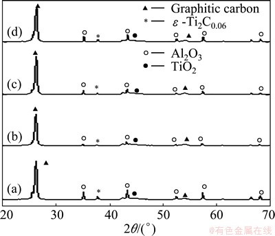
Fig. 2 XRD patterns of alumina-graphite joints brazed at 895 ��C (a), 900 ��C (b), 905 ��C (c) and 910 ��C (d) for 10 min before thermal cycling

Fig. 3 XRD patterns of alumina-graphite joints brazed at 895 ��C (a), 900 ��C (b), 905 ��C (c) and 910 ��C (d) for 10 min after thermal cycling
3.2 Microstructural examination
Figures 4 and 5 show the SEM images of the alumina-graphite brazed joints before and after thermal cycling, respectively. The magnified images of interfacial regions showed that the interfaces were free from cracks or any other defects before thermal cycling (Fig. 4). Further, it was observed that the pores of graphite were filled with a whitish phase, which was also present in the voids of braze. Thermal cycling did not affect the interfacial microstructures of the brazed joints in terms of crack or any other defects, as can be seen from Fig. 5. It is evident from Fig. 4 that during brazing operation the penetration of molten filler alloy through the pores of graphite and alumina increased with increasing the brazing temperature, which led to higher amount of whitish phase into the pores of graphite and alumina brazed at higher temperatures. This phenomenon was prominent in the case of porous graphite that was observed for alumina. The infiltration of molten alloy through the pores of graphite and alumina resulted in enhancement of the brazing reaction. Furthermore, Fig. 5 demonstrates that the amount of whitish phase content in the pores of graphite remarkably increased after thermal cycling. Thus, it can be said that the thermal cycling promotes the penetration of molten filler alloy into the pores of graphite and alumina as well as the brazing reaction.
3.3 EDX line and point analysis
Energy dispersive X-ray (EDX) analysis was performed on X to Y selective line region across the brazed joints before and after thermal cycling (Figs. 6 and 7). The analyses showed that the interfacial reaction zones were composed of Al, O, C, Ti, Ag, Cu elements. Ti was found at the interfaces of braze with graphite and alumina. Ti reacts with graphite and alumina and forms carbide and oxide, respectively. Ag and Cu of the filler alloy were distributed all over the braze. EDX data confirmed the XRD results. From EDX point analysis carried out on the braze of the joints before and after thermal cycling (Fig. 8), it can be seen that Ag was mainly present in the grayish phase of braze, which comes from the filler material. On the contrary, Cu was predominantly present in the blackish region of the braze. The whitish phase present in the pores of the graphite as well as in the braze region was identified by EDX point analysis as Ag. At the melting temperature of the filler material Ag diffused to the graphite region and penetrated into the pores of the graphite. This phenomenon proved that the graphite had some pores.

Fig. 4 Typical SEM images of alumina-graphite joints brazed at 895 ��C (a), 900 ��C (b), 905 ��C (c) and 910 ��C (d) for 10 min before thermal cycling

Fig. 5 Typical SEM images of alumina-graphite joints brazed at 895 ��C (a), 900 ��C (b), 905 ��C (c) and 910 ��C (d) for 10 min after thermal cycling
3.4 Brazing strength and hermeticity
In the brazing strength measurement method, the system gripped the one side of alumina bar and pulled down the other side of alumina bar to the downward. The same but opposite force acted on the graphite portion also. The breaking force was measured by the instrument.
The brazing strength (Q) was calculated using the well known relation as given below [19]:
Q=4F/(��d2) (1)
where F is the breaking force and d is the diameter of the loading fixture. The variations of applied force with respect to time are shown in Fig. 9. The calculated average brazing strength of the joints was 11 MPa before thermal cycling. However, it was noticed that the joint did not break at the interfacial regions after applying of 61 N but the assembly broke in the graphite side, indicating high alumina-graphite joint strength. The joint strength was not significantly affected by the thermal cycling test. After thermal cycling tests, the calculated average brazing strength of the joints was 10.37 MPa and the breaking point was again noted in the graphite side. The alumina-graphite interfacial region maintained intact after the thermal cycling tests. Therefore, it can be said that the brazing strength was obviously good. Porosity of the graphite, which was supported by the microstructural observations and EDAX analysis and the low binding energy of the graphite with respect to alumina [20,21] resulted in failure of the cohesive strength of graphite leading to breaking of the joint assembly in the graphite side before the actual brazing strength was measured. Helium leak test showed that all the alumina-graphite joints had a leak tightness of 1.33��10-7 Pa. The joints maintained that order of hermeticity even after thermal cycling 100 cycles.
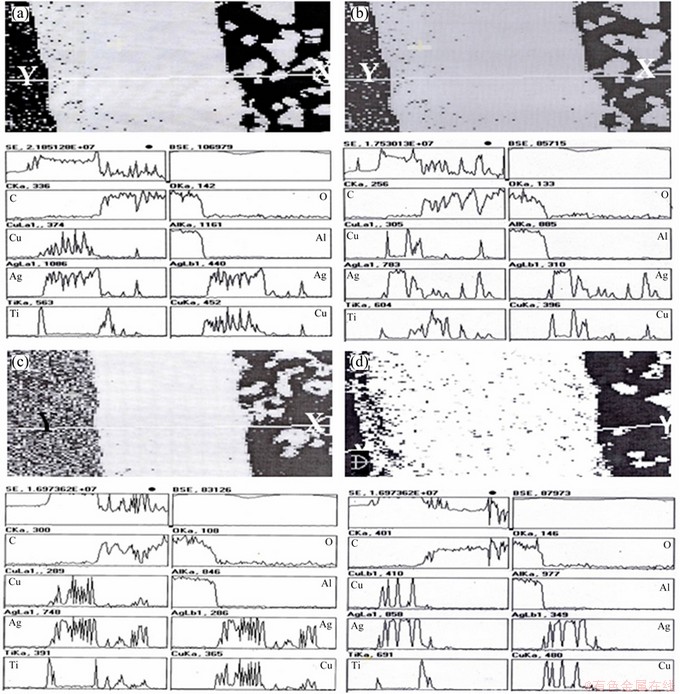
Fig. 6 Line EDAX plots for alumina-graphite joints brazed at 895 ��C (a), 900 ��C (b), 905 ��C (c) and 910 ��C (d) for 10 min before thermal cycling
4 Conclusions
1) Alumina and graphite can be successfully brazed in a vacuum furnace. The microstructural study confirmed that there were no cracks or any other defects at the joint interfaces after thermal cycling 100 cycles between 30 and 600 ��C.
2) Brazing strength of the joint was found to be quite good as the joints did not break at the interfacial regions even after the thermal cycling tests but the assembly broke in the graphite side.
3) It is expected that the present brazing technique for alumina-graphite joining can be used for very high power electron tube fabrication.

Fig. 7 Line EDAX plots for alumina-graphite joints brazed at 895 ��C (a), 900 ��C (b), 905 ��C (c) and 910 ��C (d) for 10 min after thermal cycling

Fig. 8 Typical point EDX plots of brazed alumina-graphite joints before thermal cycling for blackish phase B (a) and grayish phase G (b) and after thermal cycling for blackish phase B (c) and grayish phase G (d)

Fig. 9 Typical brazing strength measurement graphs of alumina-graphite joints before (a) and after (b) thermal cycling
Acknowledgements
The authors are very grateful to Mr. K. DASGUPTA, Director, CSIR-Central Glass and Ceramic Research Institute, Kolkata�C700 032, India, for his kind permission to publish this paper. The authors thank Dr. A. K. CHAKRABORTY and Dr. S. BYSAKH for their assistance in doing XRD, SEM and EDAX, respectively.
References
[1] GAHLAUT V, SHARMA R K, SRIVASTAVA V, ALVI P A, GHOSH S K. Effect of ceramic material on heat dissipation from multi-stage depressed collector used in high frequency travelling-wave tubes [J]. Indian Journal of Pure & Applied Physics, 2013, 51: 657-660.
[2] WANG J, JIANG N, JIANG H. The high-temperatures bonding of graphite/ceramics by organ resin matrix adhesive [J]. International Journal of Adhesion and Adhesives, 2006, 26: 532-536.
[3] HAO H Q, WANG Y L, JIN Z H, WANG X T. Joining of zirconia to zirconia using Ag-Cu-Ti filler metal [J]. Journal of Materials Processing Technology, 1995, 52: 238-247.
[4] STANDING R, NICHOLAS M. The wetting of alumina and vitreous carbon by copper�Ctin�Ctitanium alloys [J]. Journal of Materials Science, 1978, 13: 1509-1514.
[5] STORMS E K. Refractory carbides [M]. New York: Academic Press, 1967.
[6] OLIVER W C, PHARR G M. An improved technique for determining hardness and elastic modulus using load and displacement sensing indentation experiments [J]. Journal of Material Research, 1992, 7: 1564-1583.
[7] PAK J J, SANTELLA M L, FRUEHAN R J. Thermodynamics of Ti in Ag-Cu alloys [J]. Metallurgical Transaction B, 1990, 21: 349-355.
[8] KELKAR G P, SPEAR K E, CARIM A H. Thermodynamic evaluation of reaction products and layering in brazed alumina joints [J]. Journal of Material Research, 1994, 9: 2244-2250.
[9] SUENAGA S, NAKAHASHI M, MARUYAMA M, FUKASAWA T. Interfacial reactions between sapphire and silver�Ccopper�Ctitanium thin film filler metal [J]. Journal of American Ceramic Society, 1997, 80: 439-444.
[10] BARBIER F, PEYTOUR C, REYCLOEVSCHI A. Microstructural study of the brazed joint between alumina and Ti-6Al-4 V alloy [J]. Journal of American Ceramic Society, 1990, 73: 1582-1586.
[11] ZHU W, CHEN J, JIANG C, HAO C, ZHANG J. Effects of thickness on microstructure and mechanical properties of alumina Kovar-joints brazed with Ag-Pd/Ti filler [EB/OL]. Ceramics International, http://dx.doi.org/10.1016/j.ceramint.2013.11.008.
[12] DO NASCIMENTO R M, MARTINELLI A E, BUSCHINELLI A J A. Review article: Recent advances in metal�Cceramic brazing [J]. Ceramica, 2003, 49: 178-198.
[13] SHIUE R K, WU S K, O J M, WANG J Y. Microstructural evolution at the bonding interface during the early-stage infrared active brazing of alumina [J]. Metallurgical and Materials Transactions A, 2000, 31: 2527-2536.
[14] GRAMELLINI C, LANZONI E, POLI G, SPINEDI P, BELISARIO G C, SANTUCCI G. Achievement and structural characterization of joints between dissimilar materials: A graphite-carbon steel couple [J]. Materials Chemistry and Physics, 1984, 11: 591-601.
[15] TEOH S H, THAMPURAN R, SEAH W K H. Coefficient of friction under dry and lubricated conditions of a fracture and wear resistant P/M titanium-graphite composite for biomedical applications [J]. Wear, 1998, 214: 237-244.
[16] ZHONG Z, ZHOU Z, GE C. Brazing of doped graphite to Cu using stress relief inter layers [J]. Journal of Materials Processing Technology, 2009, 209: 2662-2670.
[17] SONG J, GUO Q, TAO Z, GAO X, SHEN P, SHI J, LIU L. Mo2C intermediate layers for graphite�CCu system using the molten salt method [J]. Fusion Engineering and Design, 2011, 86: 2965-2970.
[18] GHOSH S, CHAKRABORTY R, DANDAPAT N, PAL K S, DATTA S, BASU D. Characterization of alumina�Calumina/graphite/Monel superalloy brazed joints [J]. Ceramic International, 2012, 38: 663-670.
[19] ASTM D7234-12. Standard Test Method for Pull-Off Adhesion Strength of Coatings on Concrete Using Portable Pull-Off Adhesion Testers [S].
[20] SCHABEL M C, MARTINS J L. Energetics of interplanar binding in graphite [J]. Physical Review B, 1992, 46: 7185-7188.
[21] LINDSAY J R, ROSE H J, SWARTZ W E, WATTS P H, RAYBURN K A. X-ray photoelectron spectra of aluminum oxides: Structural effects on the ��chemical shift�� [J]. Applied Spectroscopy, 1973, 327: 1-5.
������-ʯīǥ����ͷ�ڵ��ӹ�Ӧ���е���ѭ����Ϊ
Nandadulal DANDAPAT1,2, Sumana GHOSH1, Kalyan Sundar PAL3, Someswar DATTA1, Bichitra Kumar GUHA2
1. Central Glass & Ceramic Research Institute, Council of Scientific and Industrial Research, Kolkata 700032, India;
2. Department of Physics, Bengal Engineering & Science University, Howrah 711103, India;
3. Institute for Plasma Research, Gandhinagar 302428, India
ժ Ҫ����Ti-Cu-Ag (68.8Ag-26.7Cu-4.5Ti������������%)Ϊǥ�ϣ���895��900��905��910 ��C�¶��£���0.67 mPa��ջ����г���10 min�����û��ý���ǥ������ǥ����������ʯī����30~600 ��C��ǥ����Ʒ������ѭ����������б�����X�����������������Ѻ�̼֮���ǿ�ҷ�Ӧͬ�Ѻ���������һ����ɨ������������ͺ����ܷ��������������ʼ��Ʒ����ѭ��ǥ����Ʒû�г����ѷ������ȱ�ݺ����������⡣ʵ��õ���ǥ��ǿ������Ľ�ͷ��
�ؼ��ʣ�ǥ����ͷ����ѭ����ǥ��ǿ�ȣ��ܷ���
(Edited by Xiang-qun LI)
Corresponding author: Sumana GHOSH; Tel: +91-33-24733469/76/77/96; Fax: +91-33-24730957; E-mail: sumana@cgcri.res.in
DOI: 10.1016/S1003-6326(14)63239-8

