��-Һ��Һ-Һ��Ӧ����������Ʊ�ԭλTiB2/Cu���ϲ���
��Դ�ڿ����й���ɫ����ѧ��(Ӣ�İ�)2020���7��
�������ߣ��µ� ������ ���� ���� �ν�̳ �ܷ� ���绪
����ҳ�룺1849 - 1856
�ؼ��ʣ�ԭλTiB2/Cu���ϲ��ϣ���Ӧ��������������ʣ�����ǿ��
Key words��in situ TiB2/Cu composite; reactive spray deposition; electrical conductivity; tensile strength
ժ Ҫ�����ù�-Һ��Һ-Һ��Ӧ���������������������˻����Ʊ�ԭλTiB2/Cu���ϲ��ϣ��Աȷ����ø��ϲ��ϵ�����֯�����ܡ����������TiB2/Cu���ϲ��ϵ�����֯��������Ҫ�ܷ�Ӧ��ʽ�����ƴ�����Ӱ�졣����Һ-Һ��Ӧ����ʹԭλ��Ӧ����ֵؽ��У���ͨ�����ƺ��˻�����ʹ���ϲ���ԭʼ�����������ܶȺ����ܵõ��Ż�������Һ-Һ��Ӧ��������Ʊ�������̬TiB2/Cu���ϲ��ϵ��ۺ�����(401 MPa��83.5% IACS)�������� ��-Һ��Ӧ��������Ʊ�������̬TiB2/Cu���ϲ��ϵ��ۺ�����(520 MPa��20.2% IACS)��
Abstract: In situ TiB2/Cu composites were fabricated by both solid-liquid (S-L) and liquid-liquid (L-L) reactive spray deposition in combination with cold rolling and annealing. The microstructure and properties of the fabricated TiB2/Cu composites were investigated. The results show that the reactive mode and rolling treatment are the main factors affecting the microstructure and properties of the TiB2/Cu composite. The in situ reaction in the L-L reaction can be carried out more completely. By controlling the rolling and annealing process, the relative density and the properties of the as-deposited composites are optimized. The comprehensive performance of the deformed TiB2/Cu composite prepared by L-L reactive spray deposition (401 MPa and 83.5% IACS) is better than that by S-L reactive spray deposition (520 MPa and 20.2% IACS).
Trans. Nonferrous Met. Soc. China 30(2020) 1849-1856
Dan CHEN, Yi-hui JIANG, Yu-fa LI, Di LIU, Jiang-tan HE, Fei CAO, Shu-hua LIANG
Shaanxi Province Key Laboratory for Electrical Materials and Infiltration Technology, School of Materials Science and Engineering, Xi��an University of Technology, Xi��an 710048, China
Received 8 November 2019; accepted 17 June 2020
Abstract: In situ TiB2/Cu composites were fabricated by both solid-liquid (S-L) and liquid-liquid (L-L) reactive spray deposition in combination with cold rolling and annealing. The microstructure and properties of the fabricated TiB2/Cu composites were investigated. The results show that the reactive mode and rolling treatment are the main factors affecting the microstructure and properties of the TiB2/Cu composite. The in situ reaction in the L-L reaction can be carried out more completely. By controlling the rolling and annealing process, the relative density and the properties of the as-deposited composites are optimized. The comprehensive performance of the deformed TiB2/Cu composite prepared by L-L reactive spray deposition (401 MPa and 83.5% IACS) is better than that by S-L reactive spray deposition (520 MPa and 20.2% IACS).
Key words: in situ TiB2/Cu composite; reactive spray deposition; electrical conductivity; tensile strength
1 Introduction
Owing to their good mechanical properties and electrical conductivity, copper matrix composites have been widely applied in major national infrastructure [1,2]. TiB2 possesses good wear resistance, corrosion resistance, and oxidation resistance and high conductivity, hardness, and melting point characteristics, which usually serves as reinforcement in copper matrix composites [3-5]. The TiB2/Cu composite has been conventionally produced by the stir casting [6], mechanical alloying [7], and powder metallurgy [8]. However, the segregation of the reinforcement, poor interfacial interactions and complex manufacturing processes are common problems in the above preparation methods [9-11]. Reactive spray deposition combines the advantages of rapid forming and an in situ reaction, which exhibits a homogeneous microstructure with fine grains, a good interface and near-net-shape formation [12].
According to the reaction mode of TiB2 synthesis, the reactive spray deposition process can be divided into two types: solid-liquid (S-L) reactions [13,14] and liquid-liquid (L-L) reactions [15-18]. LEE et al [13] prepared a TiB2/Cu composite by spray forming a Cu-Ti melt while injecting Cu-B solid powders into the spray of droplets. Because the reaction between Ti and B occurred after the deposition of Cu-Ti droplets, nanoscale TiB2 particles were formed. However, the reaction process was not easy to control, and the reinforcement tended to segregate at the grain boundary [14]. For the L-L reaction, WANG et al [15] prepared an as-deposited TiB2/Zn-30Al- 1Cu composite by carrying out an in situ reaction during the melting process. The matrix material was first melted, and the reinforcements were formed in situ in the molten alloy. Then, the composite melt was atomized to obtain a deposited billet. LEE et al [13] also prepared an as-deposited TiB2/Cu composite by using L-L reaction. Cu-2wt.%Ti and Cu-2wt.%B master alloys were first melted together and then atomized to form a deposited billet. It was easy to control the in situ reaction process during the L-L reactive spray deposition process. However, because the in situ TiB2 particles with low density were formed in the composite melt, they always floated to the upper part of the melt, which caused gravity segregation.
Since both S-L and L-L reactions have their own disadvantages, the study of TiB2/Cu composites prepared by reactive spray deposition is rare. In this work, B powders were individually injected into the spray of Cu-Ti droplets during S-L reactive spray deposition to better control the reaction process. To avoid gravity segregation, an improved L-L reactive spray deposition method was innovatively attempted by separating the Cu-Ti and Cu-B master alloys before melting. After holding at the liquid temperature of 1450 ��C for 5 min, the separated Cu-Ti and Cu-B master alloys were co-injected into the channel, where TiB2 particles were formed. In this way, TiB2 particles would not float. However, whether the S-L or L-L reaction is beneficial for spray-formed TiB2/Cu composites is unclear. Therefore, the microstructure and properties of S-L and L-L reactive spray deposition billets were compared.
2 Experimental
2.1 TiB2/Cu composite fabrication
2wt.%TiB2/Cu composites were fabricated by both S-L and L-L reactive spray deposition. Schematic diagrams of the two kinds of reactive spray deposition are shown in Fig. 1. S-L reactive spray deposition was performed by spray forming a Cu-Ti melt while injecting B powders into the spray of droplets, as shown in Fig. 1(a). The Cu-Ti master alloy was induction melted under an argon atmosphere at 1450 ��C. When the alloy was fully melted, B powders were injected into the atomizer at a flow rate of 15 L/min. The melt flowed through a graphite nozzle with an inner diameter of 5 mm, and the distance from the nozzle to the substrate was kept at 140 mm. Then, the melt stream was atomized into fine droplets by nitrogen gas at a constant pressure of 3 MPa, and a billet with a diameter of 120 mm was fabricated by manipulating the deposit stage. L-L reactive spray deposition was performed by spray forming Cu-Ti and Cu-B melts simultaneously (see Fig. 1(b)). In this work, the liquid alloys were atomized after mixing in the channel, which differs from conventional L-L reactive spray deposition. Subsequently, the atomization and deposition processes were the same as those of the S-L reaction.
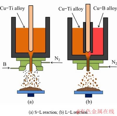
Fig. 1 Schematic diagrams of reactive spray deposition
The S-L spray-deposited billet is labeled the S-L sample, and the L-L spray-deposited billet is labeled the L-L sample. To eliminate unfavorable deposition defects and improve the relative density, cold rolling with a 40% reduction in thickness and stress-relief annealing at 200 ��C for 120 min were performed.
2.2 Property characterization
Phase identification was carried out by X-ray diffraction (XRD, XRD-7000S). The micro- structure was characterized by scanning electron microscopy (SEM, JSE-6700F) and transmission electron microscopy (TEM, JEM-3010). Samples for SEM observation were prepared by mechanical grinding and electrolytic polishing with a solution containing 70% phosphoric acid in ethanol. The relative density was measured by the Archimedes�� method. The hardness was evaluated by the Brinell hardness test method. The electrical conductivity expressed in % IACS (International Annealed Copper Standard) was examined by an eddy-current instrument. The tensile strength and elongation were tested by a tensile testing machine (HT-2402).
3 Results and discussion
3.1 Microstructure analysis
The XRD patterns of the S-L and L-L samples are given in Fig. 2. The TiB2 phase was detected in both the S-L and L-L samples, which confirmed that the in situ reaction of Ti+B��TiB2 occurred during spray deposition. The weak diffraction peak of Cu3Ti only appeared in the S-L sample. Furthermore, the lattice parameters of the Cu matrix of the two samples were calculated by using the angle reflections of (111), (200) and (220) in Fig. 2. Compared to the lattice parameter of pure copper (0.36178 nm [19]), the calculated lattice parameters of the Cu matrix of the S-L and L-L samples were 0.36221 and 0.36183 nm, respectively. The result of the L-L sample was very close to the lattice parameter of pure copper, indicating that the content of the solid solution element in the Cu matrix was barely detected and that the in situ reaction was carried out completely. The result is that the lattice parameter of the S-L sample was higher than that of pure copper, which is ascribed to the solid solution of unreacted Ti (1.76  ) in the Cu (1.27 ) matrix. The precipitation of Cu3Ti and the solid solution of Ti indicated an incomplete reaction between Ti and B in the S-L sample. For the L-L reaction, the mixed master alloys formed homogeneous Cu-Ti-B ternary liquids in the channel. Since the precipitation kinetics of TiB2 particles from ternary liquids are rather rapid [20], a relatively complete in situ reaction can be achieved in the L-L reaction. For the case of the S-L reaction, the in situ reaction depends on the impingement between B particles and Cu-Ti droplets and the dissolution of B into Cu-Ti liquids.
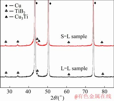
Fig. 2 XRD patterns of S-L and L-L samples
However, a small portion of Cu-Ti droplets will solidify before impingement and dissolution occur, which results in an incomplete reaction.
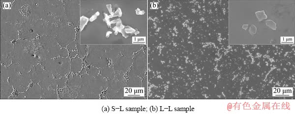
Fig. 3 Microstructures of as-deposited samples
Figure 3 shows the microstructures of the as- deposited S-L and L-L samples. According to the XRD patterns shown in Fig. 2, the reinforcement and matrix could be identified as TiB2 and Cu. The nonuniform distribution of TiB2 with a size range of 200-700 nm could be determined, including TiB2 clusters and particles. The segregation in the S-L sample was severer than that in the L-L sample, which tended to manifest as a net-work distribution. The net-work distribution was related to the relatively high cooling rate in the S-L process, as the injection of B powders into the spray cone will introduce a chilling effect. When the sprayed Cu-Ti droplets and the injected B powders reached the billet surface, a thin semisolid layer was formed, in which B diffused into the Cu-Ti droplets and reacted with Ti [13]. When partial solidification of the droplet occurred prior to deposition, the B powders accumulated around the edge of the Cu-Ti droplet, and a net-work distribution of reinforcement was formed. Figure 4 shows the TEM images of the S-L sample and L-L sample. Based on the selected area electron diffraction (SAED) pattern of the S-L sample (Fig. 4(b)), the particle was identified as B, which indicated that the B powder remained in the deposited billet. The particles in the L-L sample were identified as TiB2 by SAED analysis, and no B particles were found.
In light of the results of the Archimedes�� method, the relative density of the as-deposited S-L sample with a value of 91.12% was lower than that of the L-L sample with a value of 96.60%. On one hand, the density of deposition billets depended on the solid volume fraction of the droplet when it reached the billet surface. The rapid cooling rate of the droplet in the S-L reaction always caused a large solid volume fraction. The droplet with a high solid phase fraction had difficulty adhering to the top layer of the billet, which led to the formation of microporosity (see Fig. 3(a)). On the other hand, the density of the composite was determined by its composition, and the low density of the unreacted B powder caused the low density of the S-L sample.
With the aim of eliminating the deposition defects and improving the relative density, cold rolling and low-temperature annealing were carried out. Figure 5 shows the microstructures of deformed S-L and L-L samples. In Fig. 5(a), the spherical network became an ellipsoid shape, illustrating a dense microstructure. In Fig. 5(b), the distribution of TiB2 particles became uniform with a streamlined shape. The relative density of the two samples increased to 98.50% after cold deformation.
3.2 Evolution of properties
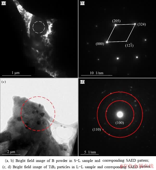
Fig. 4 TEM images of S-L sample and L-L sample
The different solidification processes of the two reaction modes gave rise to different reaction degrees, which would eventually lead to different properties. Table 1 lists the electrical conductivity, hardness, tensile strength and elongation of the S-L and L-L samples. In addition, the values listed in Table 1 show that cold rolling and annealing have a significant impact on the mechanical properties.
The electrical conductivity of the S-L sample was much lower than that of the L-L sample, which can be ascribed to the following two reasons. The main reason is that the solid solution of Ti in the Cu matrix increased the scattering ability of the electrons [21]; thus, the electrical conductivity of the S-L sample significantly decreased. The less important reason is that B and Cu3Ti impurities in the S-L sample had an unfavorable effect on the electrical conductivity. After cold rolling and annealing, the electrical conductivity of both the S-L and L-L samples increased due to the increased relative density. Because the relative density of the S-L sample had a large increment from 91.12% to 98.50%, the electrical conductivity increased substantially from 12.5% IACS to 20.2% IACS. The increasing trend of the L-L sample, by comparison, was not obvious due to the slight increase in the relative density.
For the as-deposited samples, both the tensile strength and the elongation of the S-L sample were lower than those of the L-L sample, while the harness of the two samples appeared to show an opposite trend. After rolling and annealing, the tensile strength and the hardness of the two samples were markedly improved, but the elongation was reduced. By comparing the variations in the mechanical properties, the rolling and annealing process had a stronger impact on the S-L sample than the L-L sample, as shown in Fig. 6. For example, the tensile strengths were improved by 115% and 40% for the S-L and L-L samples, respectively.
Due to the low relative density in the as-deposited samples, the microporosity may act as preferential sites for microcrack initiation during tensile testing. Since the volume fraction of the microporosity in the as-deposited S-L sample was as high as 8.88%, it became a crucial factor for the low tensile strength. However, the hardness seems insensitive to the microporosity. Due to the solid solution of unreacted Ti and the precipitation of the Cu3Ti phase in the S-L sample, the harness was comparable to that of the Cu-Ti alloys [22].
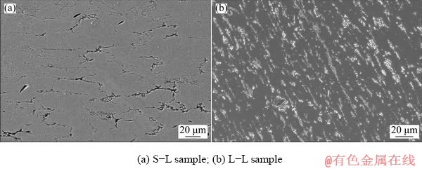
Fig. 5 Microstructures of deformed samples
Table 1 Electrical conductivity, hardness, tensile strength and elongation of S-L and L-L samples
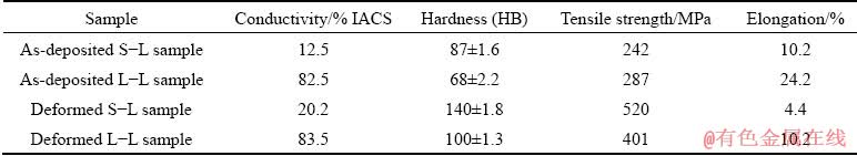
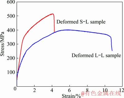
Fig. 6 Tensile stress-strain curves of deformed composites with S-L and L-L reaction modes
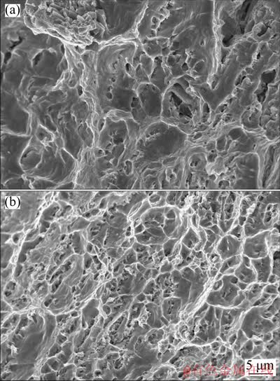
Fig. 7 Tensile fracture morphologies of deformed S-L (a) and L-L (b) samples
In combination with the tensile fracture morphology shown in Fig. 7, the tensile properties of deformed S-L and L-L samples were analyzed. Both samples exhibited an obvious dimple-like fracture, which clearly revealed ductile properties. Taking a closer look in Fig. 7, it can be seen that the fracture surface of the S-L sample contained dimples of different sizes, but the fracture surface of the L-L sample was composed of a large number of relatively uniform fine dimples. Since the microporosity was substantially removed after cold rolling and annealing, the difference in tensile properties between the two samples was mainly attributed to microstructure characteristics. A striking difference between the two samples was the distribution state of the reinforcements. For the case of the S-L sample, the distribution of reinforcements exhibited a heterogeneous form (see Fig. 3(a)). Therefore, cold rolling will result in a nonhomogeneous deformation because the reinforcement-rich regions have a much higher ability to resist deformation than the reinforcement- poor regions [23]. This nonhomogeneous deformation can be confirmed by the fracture morphology shown in Fig. 7(a), where the large and small dimples occurred at the reinforcement-poor and reinforcement-rich regions, respectively. Compared with the more homogeneous L-L sample, the cold rolling of the S-L sample led to a higher work hardening effect because the plastic deformation is mainly concentrated in the reinforcement-poor region. Accordingly, it resulted in a higher tensile strength of the deformed S-L sample than that of the deformed L-L sample.
Since the strength and electrical conductivity are two important properties of electrical engineering materials, a combination index, M, was proposed to evaluate the comprehensive performance of copper materials. The M index can be expressed as follows [24]:
 (1)
(1)
where ��b and �� represent the ultimate tensile strength and the electrical conductivity, respectively. The calculated values of the M index for the S-L and L-L samples are 5.46��106 and 13.42��106 MPa2��% IACS, respectively. Accordingly, it can be concluded that the comprehensive performance of the in situ TiB2/Cu composite prepared by L-L reactive spray deposition is much better.
4 Conclusions
(1) The in situ reaction degree and rolling treatment were the main factors affecting the microstructure and properties of the TiB2/Cu composites prepared by S-L and L-L reactive spray deposition.
(2) The injection of B powder accelerated the cooling rate of the Cu-Ti droplets for the S-L reaction, resulting in an incomplete in situ reaction and a heterogeneous composite with a low relative density. By comparison, the co-injection of the Cu-B and Cu-Ti melts for the L-L reactive spray deposition led to a relatively complete reaction and more homogeneous composites with a high relative density.
(3) The comprehensive performance of the deformed TiB2/Cu composite prepared by L-L reactive spray deposition is better than that prepared by S-L reactive spray deposition. This performance can be explained by the fact that the L-L reactive spray deposition is beneficial for the in situ reaction between Ti and B and the deposition process.
References
[1] YU Hao-yang, FANG Wei, CHANG Ruo-bin, JI Pu-guang, WANG Qing-zhou. Modifying element diffusion pathway by transition layer structure in high-entropy alloy particle reinforced Cu matrix composites [J]. Transactions of the Nonferrous Metals Society of China, 2019, 29(11): 2331-2339.
[2] PRAKASH K S, THANKACHAN T, RADHAKRISHNAN R. Parametric optimization of dry sliding wear loss of copper�CMWCNT composites [J]. Transactions of Nonferrous Metals Society of China, 2017, 27(3): 627-637.
[3] YU Zhu-li, ZHU He-guo, HUANG Jie-wen, LI Jian-liang, XIE Zong-han. Processing and characterization of in-situ ultrafine TiB2-Cu composites from Ti-B-Cu system [J]. Powder Technology, 2017, 320: 66-72.
[4] QIU Feng, DUAN Xiang-zheng, DONG Bai-xin, YANG Hong-yu, LU Jian-bang, LI Xiu-juan. Effects of Cr and Zr addition on microstructures, compressive properties, and abrasive wear behaviors of in situ TiB2/Cu cermets [J]. Materials, 2018, 11(8): 1464.
[5] LONG Fei, GUO Xiu-hua, SONG Ke-xing, JIA Shu-guo, YAKUBOV V, LI Shao-lin, LIANG Shu-hua. Enhanced arc erosion resistance of TiB2/Cu composites reinforced with the carbon nanotube network structure [J]. Materials & Design, 2019, 183: 108136.
[6] WANG Tong-min, ZOU Cun-lei, CHEN Zong-ning, LI Ming-yu, WANG Wei, LI Ren-geng, KANG Hui-jun. In situ synthesis of TiB2 particulate reinforced copper matrix composite with a rotating magnetic field [J]. Materials & Design, 2015, 65: 280-288.
[7] GUO Ming-xing, WANG Ming-pu. The relationship among microstructure evolution, mechanical property and in situ reaction mechanisms in preparing Cu�C1.6wt%TiB2 alloys [J]. Materials Chemistry and Physics, 2013, 138: 95-101.
[8] WANG Gui-song, FAN Guo-hua, GENG Lin, HU Wei-ping, HUANG Yu-dong. Microstructure evolution and mechanical properties of TiB2/Cu composites processed by equal channel angular pressing at elevated temperature [J]. Materials Science and Engineering A, 2013, 571: 144-149.
[9] JIANG Yi-hui, WANG Chen, LIANG Shu-hua, REN Jian-qiang, DU Xiang, LIU Feng. TiB2(�CTiB)/Cu in-situ composites prepared by hot-press with the sintering temperature just beneath the melting point of copper [J]. Materials Characterization, 2016, 121: 76-81.
[10] ZHANG Peng-chao, JIE Jin-chuan, GAO Yuan, LI Hang, CAO Zhi-qiang, WANG Tong-min, LI Ting-ju. Preparation and properties of TiB2, particles reinforced Cu-Cr matrix composite [J]. Materials Science and Engineering A, 2015, 642: 398-405.
[11] YANG Ber-lin, WANG Feng, ZHANG Jian-bo. Microstructural characterization of in situ TiC/Al and TiC/Al�C20Si�C5Fe�C3Cu�C1Mg composites prepared by spray deposition [J]. Acta Materialia, 2003, 51: 4977-4989.
[12] LIU Bin, LEI Qian, XIE Liu-qun, WANG Ming-pu, LI Zhou. Microstructure and mechanical properties of high product of strength and elongation Al�CZn�CMg�CCu�CZr alloys fabricated by spray deposition [J]. Materials & Design, 2016, 96: 217-223.
[13] LEE J, JUNG J Y, LEE E S, PARK W J, AHN S, KIM N J. Microstructure and properties of titanium boride dispersed Cu alloys fabricated by spray forming [J]. Materials Science and Engineering A, 2000, 277: 274-283.
[14] CHRYSANTHOU A, ERBACCIO G. Production of copper-matrix composites by in situ processing [J]. Journal of Materials Science, 1995, 30: 6339-6344.
[15] WANG Feng, ZHANG Qiang, XIONG Bai-qing, ZHANG Yong-an, LIU Hong-wei, LI Zhi-hui, LI Xi-wu. Microstructural of in-situ reaction TiB2/Zn-30Al-1Cu composites prepared by spray deposition process [J]. Advanced Materials Research, 2015, 1015: 688-691.
[16] LEE A K, SANCHEZ-CALDERA L E, CHUN J H, SUH N P. Material with novel compositions and fine microstructures produced via the mix alloy process [J]. Materials Research Society Symposium Proceedings, 1988, 132: 87-92.
[17] GAN Gui-sheng, ZHANG Lei, BEI Shu-yu, LU Yi, YANG Bin. Effect of TiB2 addition on microstructure of spray- formed Si-30Al composite [J]. Transactions of Nonferrous Metals Society China, 2011, 21(10): 2242-2247.
[18] KAUR K, PANDEY O P. Microstructural characteristics of spray formed zircon sand reinforced LM13 composite [J]. Journal of Alloys and Compounds, 2010, 503: 410-415.
[19] JIANG Yi-hui, LI Dan, ZHANG Xin-nan, ZOU Jun-tao, XIAO Peng, LIANG Shu-hua. Effects of various strengthening methods on the properties of Cu�CTi�CB alloys [J]. Materials Science and Technology, 2018, 34: 340-346.
[20] JIANG Yi-hui, LI Dan, LIANG Shu-hua, ZOU Jun-tao, LIU Feng. Phase selection of titanium boride in copper matrix composites during solidification [J]. Journal of Materials Science, 2017, 52: 2957-2963.
[21] KAVEH M, WISER N. Electrical resistivity of dislocations in metals [J]. Journal of Physics F: Metal Physics, 1983, 13: 953-961.
[22] NAGARJUNA S, BALASUBRAMANIAN K, SARMA D S. Effect of prior cold work on mechanical properties, electrical conductivity and microstructure of aged Cu-Ti alloys [J]. Journal of Materials Science, 1999, 34: 2929-2942.
[23] JIANG Yi-hui, WANG Ding-wen, XU Ying-qin, CAO Fei, LIANG Shu-hua. Fabrication and properties of in situ heterogeneous Cu/TiB2 composites with a harmonic structure [J]. Materials Letters, 2020, 263: 127032.
[24] PENG Li-ming, MAO Xie-min, XU Kuang-di, DING Wen-jiang. Property and thermal stability of in situ composite Cu-Cr alloy contact cable [J]. Journal of Materials Processing Technology, 2005, 166: 193-198.
�� ���������ԣ������� �ѣ��ν�̳���� �ɣ����绪
����������ѧ ���Ͽ�ѧ�빤��ѧԺ ����ʡ�繤��������(��)�������ص�ʵ���ң����� 710048
ժ Ҫ�����ù�-Һ��Һ-Һ��Ӧ���������������������˻����Ʊ�ԭλTiB2/Cu���ϲ��ϣ��Աȷ����ø��ϲ��ϵ�����֯�����ܡ����������TiB2/Cu���ϲ��ϵ�����֯��������Ҫ�ܷ�Ӧ��ʽ�����ƴ�����Ӱ�졣����Һ-Һ��Ӧ����ʹԭλ��Ӧ����ֵؽ��У���ͨ�����ƺ��˻�����ʹ���ϲ���ԭʼ�����������ܶȺ����ܵõ��Ż�������Һ-Һ��Ӧ��������Ʊ�������̬TiB2/Cu���ϲ��ϵ��ۺ�����(401 MPa��83.5% IACS)�������� ��-Һ��Ӧ��������Ʊ�������̬TiB2/Cu���ϲ��ϵ��ۺ�����(520 MPa��20.2% IACS)��
�ؼ��ʣ�ԭλTiB2/Cu���ϲ��ϣ���Ӧ��������������ʣ�����ǿ��
(Edited by Xiang-qun LI)
Foundation item: Projects (U1502274, 51834009) supported by the National Natural Science Foundation of China; Project (2017ZDXM- GY-028) supported by the Key Research and Development Program of Shaanxi, China
Corresponding author: Yi-hui JIANG; Tel: +86-13891941017; E-mail: jiangyihui@xaut.edu.cn
DOI: 10.1016/S1003-6326(20)65344-4

