
J. Cent. South Univ. (2019) 26: 3305-3314
DOI: https://doi.org/10.1007/s11771-019-4254-9

Finite element simulation and microstructure of two-pass inner spinning process of curved-generatrix cone cylindrical parts with annealing/quenching
HAO Zeng-liang(郝增亮)1, YANG Zhe-yi(杨哲懿)1, WEI Wei(魏巍)3, LIU Lei(刘磊)3,LUO Jun-ting(骆俊廷)1, 2, LIU Jin-heng(刘金恒)1
1. Key Laboratory of Advanced Forging & Stamping Technology and Science of Ministry of Education,Yanshan University, Qinhuangdao 066004, China;
2. State Key Laboratory of Metastable Materials Science and Technology, Yanshan University,Qinhuangdao 066004, China;
3. Hebei Construction Material Vocational and Technical College, Qinhuangdao 066000, China
 Central South University Press and Springer-Verlag GmbH Germany, part of Springer Nature 2019
Abstract: A two-pass annealing/quenching internal spinning process with small-end rotations is proposed to form a curved generatrix conical thin-walled shell. That is, annealing at 360°C for 2 h followed by the 1st pass spinning, and finally quenching in ice water after holding for 1 h at 498 °C followed by the 2nd pass spinning. ABAQUS finite element software is used to simulate the internal spinning process of the products formed under different forming parameters. The distribution laws of spinning force, the stress and strain under different forming processes were compared and analyzed. The mechanical properties and microstructure of the products are subsequently analyzed. The results show that the strain and the residual stress in the skin area of the formed products under two-pass spinning process more uniform, and the hardness and the mechanical performance are improved. The microstructure of the products formed with the 0.15 mm thickness reduction at the 2nd pass is excellent. And the second phase grain size distributed uniformly in the range of 3–6 μm. Whereas, the second phase particles are broken seriously and the size distribution inhomogeneity is increased when the thickness reduction in the skin area is greater than 0.20 mm at the 2nd pass spinning process.
Key words: curved generatrix conical; internal spinning process; annealing/quenching; small-end rotations; finite element simulation
Cite this article as: HAO Zeng-liang, YANG Zhe-yi, WEI Wei, LIU Lei, LUO Jun-ting, LIU Jin-heng. Finite element simulation and microstructure of two-pass inner spinning process of curved-generatrix cone cylindrical parts with annealing/quenching [J]. Journal of Central South University, 2019, 26(12): 3305-3314. DOI: https://doi.org/10.1007/ s11771-019-4254-9.
1 Introduction
Spin-forming is an advanced manufacturing technology and is mainly used for the formation of thin-walled rotary shell such as engine housings and bay sections [1, 2]. Spin-forming technology solves the low rigidity, large tremors, low processing precision and difficult forming problems. It also enhances material utilization and processing efficiency, improves the mechanical properties of products, and reduces manufacturing costs [3-5]. It is one of the best manufacturing processes to realize the digitization, information, flexibility, compound and precision of thin-wall shell machining process [6, 7].
HE et al [8] investigated the characteristics of uneven deformation behaviors during the process and the forming mechanism of defects by finite element simulation. The laws of different deformation behaviors on the quality of ribs were revealed, and the decisive parameters on deformation behaviors were obtained. RENTSCH et al [9] measured the geometry and thickness distribution of intermediate and final stages of a spinning component using the optical 3D digitization technique. And the quality and validity of different numerical modeling approaches were assessed. WANG et al [10] analyzed the formation of thin-walled shells with inner reinforcing ribs formed by conventional spinning technology through the design of three different blanks. The impacts of spindle speed and spinning roller radius on the formation of the thin-walled shells with inner ribs were found to be identical. WATSON et al [11] investigated the wrinkling failure mechanism of traditional metal spinning by finite element (FE) simulation. It is found that the large residual stresses in the form of bending moments in flange and are caused by roller contact, and the wrinkling failure begins when a plastic hinge is formed between the roller and the edge of the blank. HENKENJOHANN et al [12] developed a sequential approach originally for computer experiments, which was adopted and applied to optimizing the spinning process based on physical experiments. And the model was optimized by adding new design points based on the expected improvement criterion. During multi-pass conventional spinning, roller paths combined with the forward and the backward pass were used to improve the material formability. The application of the backward pass can obviously improve the uniformity of wall thickness [13]. SONG [14] investigated the forming mechanisms of these defects by experiments and finite element simulation. The results showed that excessive wall thickness reduction caused the metal bulge before the rollers, which was the main reason for backward extrusion, bulging, ring stripping and rupture. LI et al [15] studied the effects of roller paths on thickness variation, shape deviation, tool forces, and stress and strain variations. The research shows that a combined roller path with convex-concave curve could contribute to a low shape deviation, while an inverse combined roller path gives better thickness precision. In particular, the internal spinning forming process has high requirements for process equipment. Therefore, it is of great significance to guide the design of the forming process according to the simulation results of the forming process.
In this study, a two-pass annealing and quenching internal spinning process is proposed to form a curved generatrix conical thin-walled shell. ABAQUS finite element software was used to simulate the forming process of products under different forming parameters. The deformation characteristics and laws were studied and revealed, and the main forming process parameters were determined. Based on the finite element simulation results, the mechanical properties and microstructure of the spinning products were analyzed to verify the feasibility of the process.
2 Materials and process
2.1 Materials
The experimental material was a 2A14 aluminum alloy. The tensile specimens were machined by wire cutting along the axial direction of the blank. A planer was used to plane the two sides of tensile specimens. Then, some tensile specimens were subjected to a solution treatment which referred to annealing at 360 °C for 2 h and the others were subjected to quenching in ice water after holding for 1 h at 498 °C. A tensile test was performed with a strain rate of 1×10⁻² s-1 at room temperature on an Inspekt100kN electronic universal material testing machine from Germany. Figure 1 shows the actual stress–strain curve of the material after annealing and quenching.

Figure 1 True stress-strain curves of 2A14 aluminum alloy under two heat treatment processes
2.2 Internal spinning process
The processing flow diagram of spinning products is shown in Figure 2. The structure of the blank is designed based on the product size and precision requirements. The conical thin-walled shell is composed of parts, namely, the small end area, skin area, and big end area. Due to the uneven distribution of the strain and residual stress in the skin area of the formed products under one-pass forming process (process 1), the properties of the products are seriously affected. A two-pass spinning process (process 2) is proposed, which referred to annealing at 360 °C for 2 h followed by the 1st pass spinning, and finally quenching in ice water after holding for 1 h at 498 °C followed by the 2nd pass spinning. The small end is fixed in spinning processes 1 and 2, and the same feed direction and spinning sequence (skin area, big end and small end) are selected.
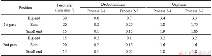
The analysis by HAN et al [3] showed that by spinning with an adaptive roller feed rate of 1.5 mm/r, the lowest level of sheet thinning is achieved. To this end, a numerical process simulation was conducted to entail the targeted adaption of the roller feed rate and the wall thickness reduction during the spinning process. In order to analyze the effects of different thickness reduction on the properties of the formed products, the processes 1 and 2 parameters were set up, which are respectively shown in Tables 1 and 2. Process 2-1 represents the first scheme of process 2 and process 2-2 represents the second scheme of process 2.
The 1st pass of process 2 is mainly the enlarging and thinning process, which has a larger spinning volume, making the wall thickness decrease a lot and making the skin form from a conical tube shape into a curvilinear generatrix cylinder. The second pass is mainly thinning and shaping process and the reduction of the blank thickness is relatively small, making the blank fully affix to the mold. The feed rate of the roller has a great influence on the blank’s closing up to punch and surface finish. Through the finite element numerical simulation analysis, it is found that the peeling phenomenon can be effectively reduced when the feed speed of the roller at the large end is increased to 30 mm/min in the first pass spinning process.
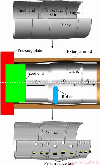
Figure 2 Process flow diagram of spinning products
Table 1 Technological parameters of process 1
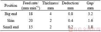
Table 2 Technological parameters of process 2
3 Finite element method
3.1 Finite element model
The geometric model of the conical thin-walled shell is established in ABAQUS finite element analysis software, as shown in Figure 3. The mode includes the blank, roller, external mold and fixed end. The roller, external mold and fixed end are set as a rigid body, and the blank is set as deformable solid that is divided into 23860 units using a hexahedral reduced integral entity unit. A dynamic explicit algorithm is adopted. The elastic modulus of the material E=80 GPa, Poisson ratio v=0.25, and the mechanical properties of the material are shown in Figure 1. The Misses yield criterion is applied, and the friction coefficient between the blank and other rigid bodies is 0.1. The simulation process is completely consistent with processes 1 and 2. The roller rotation is replaced by the blank during the forming process, and the amplitude value is used to control the axial and radial trajectories.
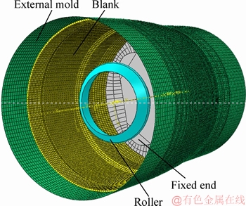
Figure 3 Finite element geometry model
3.2 FEM result analysis
3.2.1 Equivalent stress and strain
Figure 4 shows the equivalent stress and strain nephograms of formed products under process 1. Figures 5 and 6 are the equivalent stress and equivalent strain nephograms of formed products under process 2, respectively.
From Figure 4, it can be seen that the maximum equivalent stress and strain occur in the big end and small end areas, with the maximum values of 330.8 MPa and 1.591, respectively. Comparing Figure 5 with Figure 6, the equivalent stress and strain distributions of the formed products under process 2 are consistent, and the maximum value of the equivalent stress appears in the small end. The maximum equivalent stress values for the 1st pass of the formed products under process 2-1 and process 2-2 are 285.3 and 303.1 MPa, respectively, and the maximum equivalent strain values are 1.297 and 1.389, respectively. The maximum equivalent stress values for the 2nd pass of the formed products are 383.1 and 364.3 MPa, respectively, and the maximum equivalent strain values are 0.408 and 0.357, respectively.
The maximum equivalent stress value of the products of process 2 is larger than that of process 1, but the distribution is more uniform. Due to the strength and hardness of the material are increased after quenching, the reduction amount of the 2nd pass spinning process is small. The strain distribution of the products formed under the 2nd pass is more uniform than that of the 1st pass spinning process, which is more uniform for product of process 2-2. Therefore, it is necessary to control the reasonable spinning reduction amount in the 2nd pass, so that the equivalent stress and strain distribution of the products can be more uniform.

Figure 4 Equivalent stress and strain nephograms of formed products under process 1:
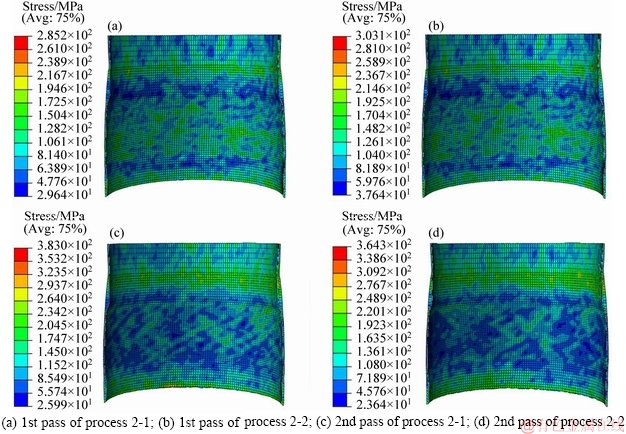
Figure 5 Equivalent stress nephograms of formed products under process 2:

Figure 6 Equivalent strain nephograms of formed products under process 2:
3.2.2 Spinning force
Figure 7 indicates the spinning force distribution curves of the formed products under process 1 and process 2. From Figure 7, it can be seen that the distribution laws of the spinning force of the process 1 and the process 2 are basically consistent, and the larger forming force is needed when forming the end of small end. This is because the end of small end is fixed, the fluidity of the material is blocked and the fluidity near the end is the worst, making the forming force the largest here. The radial spinning force and axial spinning force of process 1 are less than that of the second pass of process 2. This is because the material is quenched before the 2nd pass, making it have higher strength and hardness.

Figure 7 Distribution curves of radial (a) and axial (b) spinning force under processes 1 and 2
3.2.3 Triaxial strain
Figure 8 presents the distribution curves of the triaxial strain of the forming products under process 1 and process 2. It can be seen that the laws of the radial strain, axial strain and tangential strain are basically consistent. While the value of the radial and the axial strain is large, and the tangential strain is the smallest. The strain value of the forming product under process 1 is greater than that of process 2 and the fluctuation range is relatively large. Process 1 has a large amount of spin and the mobility of the materials is nonuniform which directly completes the expansion, thinning and fitting mold process. The triaxial strain in the 2nd pass of the forming products is smaller than that of the 1st pass, and the triaxial strain at the skin area and small end of the products is stable. It can be seen that the triaxial strain distribution in the skin area of the product formed under spinning process 2-2 is more uniform, and the triaxial strain values are much small, which indicates that the forming performance of the product under process 2-2 is excellent.
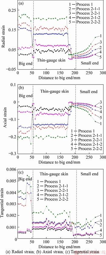
Figure 8 Triaxial strain curves of products under processes 1 and 2:
4 Experimental results
4.1 Products
The spinning forming of the blank is conducted using a spinning machine with a maximum spinning force of 2500 kN and a maximum spindle machining accuracy of 0.01 mm. The forming process parameters are consistent with the finite element simulations. The inter surfaces of the products formed with processes 1 and 2 are indicated in Figure 9. The inner surface of the product of process 2 is flatter, and the tool marks of roller are relatively small. This is because the spinning amount of the 2nd pass of spinning process 2 is small, the fluidity of the material is well, and the overall fluidity is relatively uniform.

Figure 9 Internal surfaces of products:
4.2 Hardness
The hardness of the surface of the formed products was measured by the MVS-1000D1 digital microhardness tester. The test was carried out at 6 points taken from the each part of the formed product under processes 1 and 2. Figure 10 displays the hardness curves of the formed products under processes 1 and 2. It can be seen that the hardening phenomenon exists in the spinning process, and the quenching process improves the strength and hardness of the products. Therefore, the hardness of the formed products under processes 2-1 and 2-2 is much larger than that of process 1.

Figure 10 Hardness distribution curves of products under processes 1 and 2
4.3 Residual stress
The specimens in the large end, the skin and small end areas of the products of the processes 1 and 2 were processed via wire cutting. Then, the specimens were polished and their residual stress was measured using an X-ray diffraction. The residual stress distribution curves of the test and simulation are shown in Figure 11. The measured residual stress in the test is consistent with the simulation results. At the same time, the shear and axial residual stresses of the products are compressive stresses. The residual stresses at the skin area of the product of process 1 are greater than those of process 2. The residual stress in the skin area of the formed product under process 2-2 is more stable. It can be seen that the process parameters of process 2-2 can significantly improve the residual stress distribution of the product forming and reduce the peak value of residual stress.
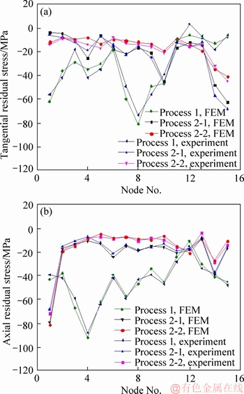
Figure 11 Residual stress results of test and simulation
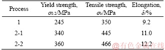
4.4 Mechanical properties
The skin area is the key part of products, which requires high strength and hardness. In this paper, the mechanical properties of standard tensile specimens cut from the skin area of the products formed under processes 1 and 2 were tested. The results of mechanical properties are shown in Table 3. The yield strength, tensile strength and elongation of the skin area of the products formed under process 2 are obviously higher than those of the product under process 1. Especially, the mechanical properties of the product formed under process 2-2 are excellent.
Table 3 Mechanical properties of products
4.5 SEM
The difference between the forming properties of the products of the two processes can be directly reflected by the microstructure. The specimens in the large end and the skin and small end areas of the products of processes 2-1 and 2-2 were processed via wire cutting. Then, the specimens were polished and corroded with 5% HF. Then, the microstructure and fracture morphology of the fracture specimens were observed under a scanning electron microscope.
Figure 12 illustrates the microstructure in each part of the products of process 2. The circumferential fiber structure and small holed defects are formed in all parts of the products, because the spinning is a strong deformation process, and the large deformation in the circumferential grain breaks the grain boundaries into fibrous tissues. The number and size of the holes in each part of the product formed under process 2-2 are obviously less than that of process 2-1, especially in the skin area. This indicates that the forming defects of the products formed under process 2-2 parameters are small and the forming performance is good, which is consistent with the results of finite element simulation.
Figure 13 denotes the fracture morphology in each part of the products of process 2. Figure 13 shows that the size of dimples at the fracture surface of the product of process 2-1 is irregular, and the second phase distributed at the fracture surface is obviously non-uniform. The second phase grain size is in the range of 2–8 μm. However, the dimple and the second phase grain distribution in the fracture of the product of process 2-2 are uniform, and the second phase grain size is in the range of 3–6 μm. The deformation in the skin part of the product formed of process 2-2 is regular, and the forming performance of the product is excellent, which is consistent with the finite element strain analysis results.
5 Conclusions
1) The spinning force and traixial strain floating bands of the products formed under process 2-2 are more stable. In addition, the hardness and the mechanical performance of the product are improved. And the parameters of the process 2-2 can significantly improve the residual stress distribution of the product forming and reduce the peak value of residual stress.
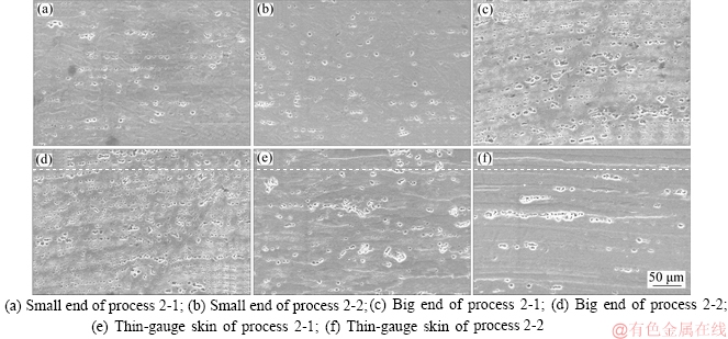
Figure 12 Microstructures of spinning products of process 2:
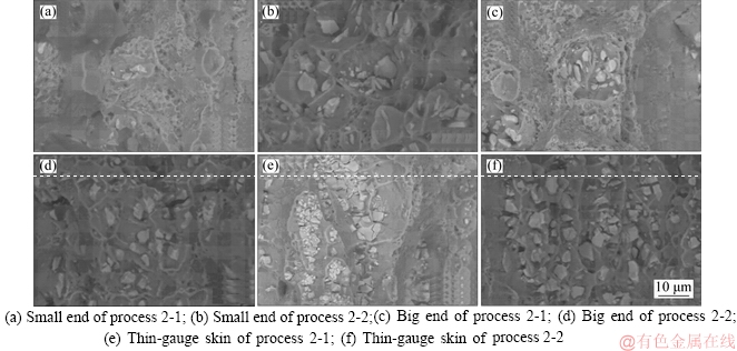
Figure 13 Fracture morphology of spinning products of process 2:
2) The microstructure of the products is excellent when the thickness reduction in the skin area is 0.15 mm at the 2nd pass spinning process. And the second phase grain distribution is uniform, the second phase grain size is distributed in 3-6 μm. Whereas, when the thickness reduction in the skin area is greater or equal to 0.20 mm at the 2nd pass spinning process, the second phase particles are broken seriously and the size distribution is inhomogeneity increased.
3) The skin area is the key part for conical thin-walled shells that requires uniform microstructures and small residual stress. Therefore, the process parameters of the spinning forming process 2-2 with good forming performance in the skin area of the product should be selected.
References
[1] MUSIC O, ALLWOOD J M, KAWAI K. A review of the mechanics of metal spinning [J]. Journal of Materials Processing Tech, 2010, 210(1): 3-23. DOI: 10.1016/ j.jmatprotec.2009.08.021.
[2] WUEST H, BOMMER L, HUBER A M, GOLL D, WEISSGAERBER T. Preparation of nanocrystalline Ce1-xSmx (Fe,Co)11 Ti by melt spinning and mechanical alloying [J]. Journal of Magnetism & Magnetic Materials, 2017, 428: 194-197. DOI: http://dx.doi.org/ 10.1016/j.jmmm. 2016.12.036.
[3] HAN Z R, FAN Z J, XIAO Y, JIA Z. A research on thickness distribution of oblique cone in dieless shear spinning [J]. The International Journal of Advanced Manufacturing Technology, 2017, 90(9-12): 2901-2912. DOI: 10.1007/ s00170-016-9565-5.
[4] YANG M, ZHANG L, HAN X S, CHENG F L. Two-stage stochastic approach for spinning reserve allocation in dynamic economic dispatch [J]. Journal of Central South University, 2014, 21(2): 577-586. DOI: 10.1007/s11771-014-1976-6.
[5] HE W, WENCHEN X, DEBIN S, WU H, XU W C, SHAN D B, JIN B C. An extended GTN model for low stress triaxiality and application in spinning forming [J]. Journal of Materials Processing Technology, 2019, 263: 112-128. DOI: 10.1016/j.jmatprotec.2018.07. 032.
[6] LI H W, YAO X, YAN S L, HE J Z, ZHAN M, HUANG L. Analysis of forming defects in electromagnetic incremental forming of a large-size thin-walled ellipsoid surface part of aluminum alloy [J]. Journal of Materials Processing Technology, 2018, 255: 703-715. DOI: https://doi.org/ 10.1016/ j.jmatprotec. 2018.01.024.
[7] LUO B F, LI X H, ZHANG X, LUO Y Z. Drum instability of thinning spinning ultrathin-walled tubes with large diameter-to-thickness ratio [J]. Journal of Central South University, 2015, 22(7): 2456-2462. DOI: 10.1007/s11771- 015-2773-6.
[8] YANG He, ZHAN Mei, LI Tian, WANG Qiao-ling. Advances in spinning of aluminum alloy large-sized complicated thin-walled shells [J]. The Chinese Journal of Nonferrous Metals, 2011, 21(10): 2534-2550. DOI: 10.1007/s12598-011-0191-y. (in Chinese)
[9] RENTSCH B, MANOPULO N, HORA P. Numerical modelling, validation and analysis of multi-pass sheet metal spinning processes [J]. International Journal of Material Forming, 2017, 10(4): 641-651. DOI: 10.1007/s12289-016- 1308-5.
[10] WANG Z, MA S. Analysis of thin-walled shells with inner ribs formed by inner spinning technology [J]. Materials Research Innovations, 2016, 19(5): 101-105. DOI: 10.1179/ 1432891715z.0000000001343.
[11] WATSON M, LONG H. Wrinkling failure mechanics in metal spinning [J]. Procedia Engineering, 2014, 81: 2391-2396. DOI: 10.1016/j.proeng.2014.10.339.
[12] HENKENJOHANN N, GOBEL R, KLEINER M, KUNERT J. An adaptive sequential procedure for efficient optimization of the sheet metal spinning process [J]. Quality & Reliability Engineering International, 2010, 21(5): 439-455. DOI: 10.1002/qre.732.
[13] GAN T, YU Zhong-qi, ZHAO Y X, LAI X M. Effects of backward path parameters on formability in conventional spinning of aluminum hemispherical parts [J]. Transactions of Nonferrous Metals Society of China, 2018, 28(2): 328-339. DOI: 10.1016/S1003-6326(18)64666-7.
[14] SONG X F. Forming mechanism of defects in spinning of large complicated thin-wall aluminum alloy shells [J]. Journal of Plasticity Engineering, 2013, 20(1): 31-36. DOI: 10.3969/j.issn.1007-2012.2013.01.007.
[15] LI Y, WANG J, LU G D, PAN G J. A numerical study of the effects of roller paths on dimensional precision in die-less spinning of sheet metal [J]. Journal of Zhejiang University A, 2014, 15(6): 432-446. DOI: 10.1631/ jzus.A1300405.
(Edited by FANG Jing-hua)
中文导读
曲母线锥筒形件退火/淬火-2道次内旋压成形有限元仿真及制品的微观组织
摘要:本文提出大型锥筒形薄壁壳体小端起旋退火/淬火-2道次内旋压成形工艺,即 360 °C保温2 h毛坯退火-第1道次旋压-498 °C保温1 h水淬-第2道次旋压。采用ABAQUS有限元软件对不同工艺参数下的成形过程进行有限元模拟,对比分析不同成形工艺下的旋压力、应力和应变的分布规律,并对旋压制品的力学性能及微观组织进行分析。结果表明:2道次内旋压下成形件的应变和残余应力较均匀,硬度和力学性能得到改善;第2道次成形时蒙皮部分减薄量为0.15 mm时制品的组织性能较好,第二相晶粒尺寸在3~6 μm区间内分布均匀,而当蒙皮部分减薄量超过0.20 mm时,容易造成制品的第二相粒子破碎严重,尺寸分布不均匀性增加。
关键词:曲母线锥筒形件;内旋压;退火/淬火;小端起旋;有限元模拟
Foundation item: Project(51775479) supported by the National Natural Science Foundation of China; Project(E2017203046) supported by the Natural Science Foundation of Hebei Province, China
Received date: 2018-12-26; Accepted date: 2019-03-21
Corresponding author: LUO Jun-ting, PhD, Professor; Tel/Fax: +86-335-8052253; E-mail: luojunting@ysu.edu.cn; ORCID: 0000-0002- 2694-534x

