
Formation of Al-Ni master alloys using nickel anode
CAO Da-li(曹大力)1, WANG Ji-kun(王吉坤)2, SHI Zhong-ning(石忠宁)3,
WANG Zhao-wen(王兆文)3, MA Lei(马雷)1, WANG Hui-hua(王惠华)1
1.School of Materials Science and Engineering, Shenyang Institute of Chemical Technology, Shenyang 110141, China;
2. Science and Technology Department, Yunnan Metallurgy Group, Kunming 650016, China;
3. School of Materials and Metallurgy, Northeastern University, Shenyang 110006, China
Received 15 July 2007; accepted 10 September 2007
Abstract: Nickel anode was investigated as a potential anode of aluminium electrowinning for preparation of Al-Ni master alloys. The electrolysis tests were carried out in Na3AlF6-Al2O3 based melts at 940 ℃. The results show that the cell voltage during electrolysis has only minor instability, and there exists NiO phase in electrolyte after 0.5 h electrolysis. Ni content in Al-Ni master alloys increases with increasing the electrolysis time. Concentration limit of Ni in Al-Ni master alloys can be up to 33.8% (mass fraction). However, substantial corrosion of the Ni-metal substrate is observed, and the oxide scale on the nickel anode after electrolysis is porous and loose that does not prevent corrosion of the substrate.
Key words: inert anode; Ni-metal anode; Al-Ni alloy; electrolysis; corrosion
1 Introduction
If inert anodes were successfully developed and applied, it could have significant energy, cost, productivity and environment benefits for the aluminium industry[1-2]. So most research have focused on inert anode and considerable progress has resulted with respect to metal-based, oxide-based and cermet-based inert anodes[3-5].
Metallic anodes have several potential advantages, such as notably low electrical resistance, good electrical connections, and ease of fabrication, and the formation of an oxide layer at electrolyte/anode surface which can prevent anode from molten electrolyte, so it is suitable candidate. HRYN[2] have tested a number of alloys, his works showed that some metal anodes could perform well, and voltage traces of some alloys were indistinguishable from platinum; however, a significant degree of metal contamination of the Al-product was reported. And the challenge for metal anode that have metal corrosion in the high temperature electrolyte, and subsequent contamination of the Al-metal product were also reported[4-5]. Meanwhile Alcoa company’s inert anode tests in aluminium industry met frustration[6]. All of these make us see that it seems to have a long way to go for inert anodes in industrial successful applications.
Raney Ni catalyst was wildly applied in all kinds of chemical reaction, and it is particularly useful for catalyzing the hydrogenation reaction. Raney Ni catalyst was prepared by alkali leaching of a commercially available crystalline Ni-Al alloy[7-9]. Meanwhile, Ni can improve Al and its alloys’ high temperature strength and stability in dimension, and Ni can reduce the hazardous effects of Fe in Al alloys. In general, Ni is added to Al alloys in the form of Al-Ni master alloys. So Al-Ni master alloy is very important material.
Metal nickel has useful bulk properties such as good electrical conductivity and fracture toughness. So it is ideal anode materials to produce Al-Ni master alloy.
If Al-Ni master alloys were successfully produced in industrial cell using Ni-based anode, maybe it can have the advantages and avoid the serious problems of the Al-metal product contamination, bringing enormous economic and environmental benefits.
Economic benefits include elimination of the carbon anode consumed, potentially lower anode costs, less operating labor, increased flexibility in cell design, and much thermally efficient cell;
Environmental benefits include global reduction or elimination of CO2 emission, reduction or elimination perfluorocarbon (PFC) emission, improved industrial hygiene, and the reduction of polycyclic aromatic hydrocarbon, carbonyl sulphide, and gaseous fluoride emissions.
There are hardly reports about the preparation of Al-Ni master alloys in the cell. In the work, we report primary tests of combining Al-Ni master alloys with Ni anode in aluminium cell.
2 Experimental
Electrolysis experiments were conducted in a lab-scale cell as shown schematically in Fig.1. The graphite crucible (d 70 mm×90 mm) which was lined on the inside with a corundum cylinder (inner diameter is 50 mm), was contained in a steel cylinder crucible, which served as the conductor of the current to the cathode. The steel cylinder crucible was housed inside a vertical electric-resistance furnace. A section of alumina ceramic tube was placed inside the graphite crucible to block current flow through the side-walls, and thus defined the cathode area as the crucible bottom.
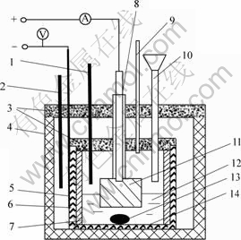
Fig.1 Schematic diagram of laboratory electrolysis cell: 1―Thermocouple measuring temperature; 2―Thermocouple controlling temperature; 3―Lid; 4―Electric furnace; 5―Iron crucible; 6―Graphite crucible; 7―Alumina corundum lining; 8―Anode rod and alumina sleeve; 9―Feeder pipe; 10―Vent pipe; 11―Ni anode; 12―Electrolyte; 13―Al-Ni alloy; 14―High-purity graphite cathode
Both the anode and the graphite crucible were connected to a DC power supply.
The electrolyte consisted of sodium fluoride and aluminum fluoride mixture with a cryolite ratio of 2.2, Al2O3, CaF2, LiF and Ni2O3. The addition of Ni2O3 was limited to 0.1%/h in cryolite in order to avoid the problems of serious sludge formation at the bottom of the cell during electrolysis, and the temperature was kept at 1 213 K. The total mass of the electrolyte was 500 g and 50 g aluminium metal was used. The interpolar distances between the working face of the anode and the surface of the cathode were 36-41 mm. The duration of the electrolysis for each run was from 30 min to 2 h. The anodic current density was 1.21-1.51 A/cm2, and the cathodic current density was 0.81 A/cm2.
3 Results and discussion
3.1 Cell voltage
The cell voltage fluctuated within the range of 6.5-10.0 V, which was caused by higher anodic current density, and the cell voltage can fall when anodic current density decreased. At the beginning of the electrolysis, the cell voltage was 8.2 V, and the cell voltage increased directly to 10.0 V within 5 min. Because the lower temperature on the anode surface made cryolite sludge formation, the anode voltage increased. With the electrolysis going along, the cryolite sludge was dissolved in the melt and the oxide film has lower electronic resistance, so the cell voltage fell to 6.4 V within 10 min. Because the oxide film got thicker and thinker, the cell voltage showed increasing trend like a line after 10 min, and the cell voltage kept 6.6 V at 60 min as seen in Fig.2.
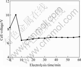
Fig.2 Cell voltage vs. electrolysis time
3.2 electrolyte composition after electrolysis
Fig.3 shows XRD pattern of electrolyte after 0.5 h electrolysis. There existed Na3AlF6, Na5Al3F14, NiO, CaF2, LiF, Al2O3 phase, without Ni2O3 or NiFx phase. The NiO formation may be
Ni2O3=NiO+O2 (electrolysis)
And
Ni+O2=NiO (anode oxidation)
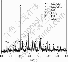
Fig.3 XRD pattern of electrolyte after 0.5 h electrolysis
3.3 oxidation of anode
Fig.4 shows the Ni anode shape after 2 h electrolysis. There was thick oxide scale and electrolyte around anodic surface. The oxide in the anodic surface dipping electrolyte did not result in spallation during the course of electrolysis. The colour of surface oxide was green, and the oxide was mainly consisted of NiO by XRD.
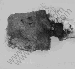
Fig.4 Anode shape after 2 h electrolysis
SEM image of oxide film after 2 h electrolysis is shown in Fig.5. The surface was relatively loose and porous. Oxygen and melts can penetrate along the porous to erode anode. And the oxide scale was not well adhered to the Ni substrate. So Ni anode could be corrupted and the depth of corrosion increased with the increasing of electrolysis time.
Fig.6 presents the anode shape before and after electrolysis, and the wear rate can be calculated from the relationship between corrosive depth and the duration of electrolysis. The wear rate of anode was 1.08 mm/h after 0.5 h electrolysis, 0.38 mm/h after 1 h, and 0.33 mm/h after 2 h when anode current density was 1.28 A/cm2.
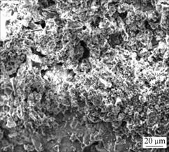
Fig. 5 SEM image of Ni anode surface oxide scale
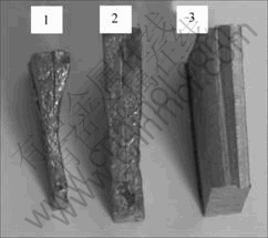
Fig.6 Anode shape before and after electrolysis: 1―Anode shape after 5 h electrolysis; 2―Anode shape after 2 h electrolysis; 3―Anode shape before electrolysis
3.4 Content of Ni in Al-Ni master alloy
The content of Ni in Al-Ni master alloy increased with increasing the electrolysis time shown as Fig.7. Ni content was 5.48% after 30 min, then up to 32.98% after 90 min and 33.82% after 120 min.
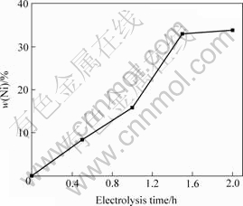
Fig.7 Ni content in Al-Ni alloy as function of duration of electrolysis at 1 233 K
Al-Ni binary diagram[10] is given in Fig.8. Around 33.8% Ni may be contained in the liquid alloy at 940 ℃, as read from the liquidus line. In order to prevent the problems with serious sludge formation at the bottom of the cell during electrolysis, the content of Ni must be lower than 34.0% at 940 ℃, so it is safety to produce Al-20%Ni in cell.
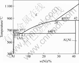
Fig.8 Al-Ni binary diagram
3.5 Forming mechanism of Al-Ni alloys
The forming mechanism of Al-Ni master alloys may be as follow:
1) Al thermoreduce Ni2O3
Aluminum has a high affinity for oxygen. Whether Al can reduce Ni2O3 depends on the difference in the oxygen affinity of Al and Ni concerned, and the reaction of interest to the present work can be represent as
Ni2O3(dissolved)+2Al(l)=2Ni(Al)+Al2O3(dissolved) (1)
for T=1 213 K, the standard Gibbs energy of reaction  kJ/mol. This highly negative value of the standard Gibbs energy of reaction shows that Eqn.(1) is strongly shifted to the right. Thus, Ni2O3 will react with aluminum to form Al-Ni alloy.
2) Electrochemical deposition
Standard decomposition potentials may be determined from Gibbs energy, and for 1 213 K the following value for the NiO was calculated: Ed(NiO)= 0.679 V.
The corresponding decomposition potential of alumina was found to be 2.223 V. Thus, Ni may therefore be deposited electrochemically from the bath at a considerably lower voltage than for aluminum in a cryolite melt.
The Ni deposited electrochemically and Al thermally reduced nickel oxide dissolve molten aluminum to form Al-Ni master alloy.
4 Conclusions
1) Although it seems to have a long way to go for inert anodes in successful industrial applications, the method that preparing Al-based master alloys by using metal anode in the cell may be successfully employed in industry.
2) Al-Ni master alloys can be prepared using Ni-metal anode in cell, and concentration limit of Ni in Al-Ni master alloys can be up to 33.8% at 1 213 K.
3) Ni anode is eroded and oxidized during electrolysis, the oxide scale on the nickel anode is porous and loose, and the oxide scale is not well adhered to the Ni substrate, which does not prevent corrosion of the substrate.
4) The forming mechanism of Al-Ni master alloys may be Al thermoreducing Ni2O3 and nickel oxide electrochemical deposition to dissolve molten Al.
References
[1] SHI Zhong-ning, XU Jun-li, QIU Zhu-xian, GAO Bing-liang, WANG Zhao-wen. Copper-nickel superalloys as inert alloy anodes for aluminum electrolysis[J]. JOM , 2003, 65(11): 63-65.
[2] HRYN J N, PELLIN M J. Cell testing of metal anodes for aluminum electrolysis[J]. Light Metals, 1999: 475-483.
[3] QIU Zhu-xian. Preparation aluminium by prebake cell[M]. Hefei: China Mineral University Press, 2005. (in Chinese)
[4] CAO Da-li, SHI Zhong-ning, WANG Ji-kun, WANG Zhao-wen, QIU Zhu-xian. Formation of aluminum-iron master alloys using plain carbon steel anode[J]. Light Metals, 2007: 483-486.
[5] SHI Zhong-ning. Preparation and investigation of metals and Metal-Al2O3 inert anode for aluminum production[D]. Shenyang: Northeastern University, 2003: 56. (in Chinese)
[6] GUO Jian-jing. Alcoa company’s inert anode test in aluminium indusry met frustration[J]. Manufacture Technology of Light Alloys, 2002,30(9): 22-26. (in Chinese)
[7] PAVEL K, LIBOR C. Characterization of chirally modified Raney nickel and compounds of tartaric acid and nickel[J]. Applied Catalysis, A: General, 2002, 223: 43-55.
[8] DANIEL C, CAROLINA M, STEVEN. Oligomerization of methane via microwave heating using Raney nickel catalyst[J]. Journal of Catalysis, 2003, 218: 201-208.
[9] KANIBOLOTSKY D S, BIELOBORODOVA O A, KOTOVA N V. Thermodynamic properties of liquid Al-Si and Al-Cu alloys[J]. Journal of Thermal Analysis and Calorimetry, 2002, 70: 975-983.
[10] PHILIPPS. Metal annotated equilibrium diagram series[M]. Beijing: Metallurgical Industry Press, 1955.
Foundation item: Projects (50334030; 50304005) supported by the National Natural Science Foundation of China; Project (20041010) supported by Ph.D Fund of Liaoning Province, China
Corresponding author: CAO Da-li; Tel: +86-24-83680245; E-mail: caodali2008@126.com
(Edited by CHEN Ai-hua)

