1) Continuity equation
 (3)
(3)
2) Momentum equation
 (4)
(4)
3) Energy equation
 (5)
(5)
2.3 Boundary conditions
Boundary conditions for flow field were composed with constant mass flow rate at inlet, Neumann condition at outlet, and no-slip conditions at the boundary walls. Constant wall heat flux of  =1 000 W/m2 was set as the boundary condition for thermal field. Fluid inside the coiled tube was water.
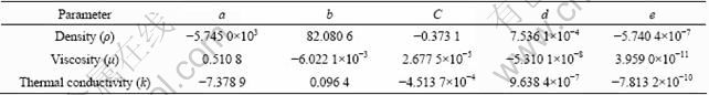
Fluid properties usually vary with temperature for low speed flow and Eq. (6) is representing functional expression of their variation. Values of coefficients in Eq. (6) for different properties are listed in Table 1.
 (6)
(6)
2.4 Numerical analysis
The governing equations were discretized with the second order upwind scheme. The SIMPLE algorithm [17] was adopted to connect momentum equation and continuity equation through pressure correction terms. The set of discretized difference equations were solved with Fluent V6.3.26 software [18].
Table 1 Coefficients of property function
3 Results and discussion
3.1 Characteristics of flow field
For identifying flow characteristics, upfront analysis was performed for cold flow with constant flow properties by excluding heat transfer effect. Inside the coiled tube (as shown in Fig.1), analysis shows that centrifugal force is applied to shift fluid from inner boundary (inner) to outer boundary (outer) along mid-plane in cross section. Magnitude of the centrifugal force is known to be proportional to the square of mean mainstream velocity and inversely proportional to the radius of curvature. To have force balance with the centrifugal force, pressure gradient is formed across tube cross section and resulting iso-pressure distribution is formed, as shown in Fig. 2.
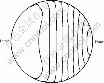
Fig. 2 Contours of iso-pressure distribution in cross section
In any certain cross section, boundary layer has low velocity due to viscous effect and flow velocity in circumferential direction, and vθ has the same characteristics. The low velocity yields small centrifugal force in the boundary layer compared to center of cross section. Meanwhile, pressure gradient is formed from outside to center of curvature, as shown in Fig. 2. Therefore, small centrifugal force and high pressure eventually push fluid from outer to inner to satisfy mass conservation. Along the mid-plane, however, flow velocity has usually high value to have large centrifugal force, and this yields fluid moving to outer boundary from inner side. As a result, the secondary flow is formed in the cross section to have two-symmetric circulating cells as shown in Fig. 3. Since the secondary flow is formed mainly due to the centrifugal force, its strength is also determined following the same proportionality with the centrifugal force, i.e., square of the flow velocity (or Re) and inverse of the radius of curvature. The spiral coiled tube has increased radius of curvature along downstream, thus the secondary flow strength is reduced as it goes to downstream and this trend is also shown in Fig. 3.
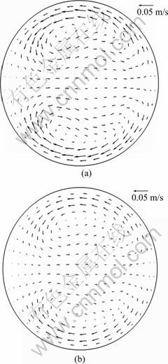
Fig. 3 Velocity vectors of secondary flow for Re=1 000: (a) θ=3π; (b) θ=9π
In the straight tube, the maximum velocity location appears at the center line. However, it is shifted to outer region in the coiled tube due to extra body force as considered. Revised velocity distribution increases velocity gradient and pressure gradient in the outer region to have the secondary flow. The secondary flow increases fluid transfer across cross section, which eventually enhances energy transfer. Due to this nature, it is important to evaluate the effect of the secondary flow. This can be done with momentum shifting parameter, Mx [19]:
 (7)
(7)
where Mx is defined as degree of momentum shifting using momentum and moment of momentum balance. Figure 4 shows geometric relationship with some definitions. Parameter ?Ai represents infinitesimal area; xi is x-direction distance of infinitesimal section from center of cross section; ri is radius of cross section.
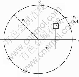
Fig. 4 Geometry for definition of momentum shifting
Since momentum shifting is resulted from the secondary flow, the momentum shifting parameter, Mx depends on Re and the radius of curvature directly. Figure 5 presents variation of Mx along downstream (increasing radius of curvature) for different Re. As it goes to downstream from inlet (θ=0) to outlet (θ=12π) of the spiral coiled tube, the radius of curvature is increased to have smaller centrifugal force yielding reduction of Mx. This trend is consistent even for different values of Re. On the other hand, increasing Re increases the centrifugal force to have higher value of Mx at the fixed downstream location. The effect of Re appears more apparent than curvature effect since the centrifugal force is proportional to square of the flow velocity while it is inversely proportional to the radius of curvature.
The spiral coiled tube is widely used in heat exchangers, and the most important design parameters for the heat exchangers are pressure drop and heat transfer capacity. To find the pressure drop effect in the coiled tube, common non-dimensional friction factor is adopted as
 (8)
(8)
where ?p is pressure difference between inlet and outlet, dh is hydraulic diameter of cross section, L is tube length from inlet (I) to outlet (O), and  is cross-sectional mean flow velocity. The pressure drop in the tube flow is affected by surface friction. In the straight tube, its slope is constant and inversely proportional to Re for laminar fully developed flow expressed as
 (9)
(9)
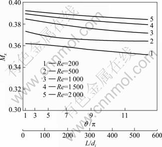
Fig. 5 Variation of momentum shifting parameter with streamwise velocity along spiral coiled tube from inlet to outlet
The coiled tube has even thinner boundary layer due to momentum shifting, which results in higher pressure drop compared to the straight tube. To find its trend, ratio of friction factors of the coiled tube to the straight tube, fc/fs, is summarized in Fig. 6. In this figure, fc/fs varies along downstream from inlet (I) to outlet (O) with different Reynolds numbers while horizontal axis represents square root of the Dean number ( ) including the curvature effect. All the values of fc/fs are larger than one, showing that friction factor of the coiled tube is larger than that of the straight tube. These values also increase along with the increase in Re and κ, indicating the increase of similar trend in flow velocity and curvature ratio. For the same Re, fc/fs is increased with the Dean number increasing. Dean number is increased with the increase of curvature ratio, which means the decrease of the radius of curvature. Therefore, inverse proportionality of the radius of curvature on flow characteristics is consistently kept. For the same Dean number, fc/fs is increased as Re increases and its increasing trend is higher compared to that of constant Re case. Increasing trend of fc/fs, therefore, shows rather strong dependency on Re than curvature ratio due to the difference in proportional order of two parameters. To compare the characteristics of friction factor variations for the spiral coiled tube and helical coiled tube, the values of fc/fs are extracted at mid-plane between inlet (I) and outlet (O) to have fixed radius of curvature, as shown in Fig. 6. The line reveals linear proportionality with square root of the Dean number(
 ) for the case with the same radius of curvature and shows the same tendency of friction factor variation with the helical coiled tube flow as reported in various studies [8].
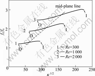
Fig. 6 Comparison of friction factor ratios for different Re and curvature ratios
3.2 Characteristics of thermal field
Once flow is fully developed in circular straight tube, the mean fluid temperature determined by Eq. (10) has linear distribution along downstream direction (Ls):
 (10)
(10)
The mean surface temperature also retains the same gradient with that of the mean fluid temperature but has constant difference in magnitude as
 (11)
(11)
With constant heat flux boundary condition, mean fluid temperature in the spiral coiled tube and mean surface temperature are presented along downstream direction in Fig. 7.
In this figure, mean temperatures of fluid and surface show same linear variation trends with those for the straight tube. The difference of temperatures, (Ts-Tm), is also maintained as nearly constant. This indicates temperature distribution in the spiral coiled tube has common characteristics with the straight tube.
Heat transfer performance of heat exchanger is often explained with mean Nu. Figure 8 shows mean Nu distribution in the spiral coiled tube, after normalizing with mean Nu in the straight tube,
  for different mass flow rates and κ. It is well known that has constant value of 4.36 in the straight tube under constant heat flux boundary condition once flow is fully developed. From Fig. 8,
  is consistently found to have higher value compared to . This can be explained with existence of the secondary flow in the spiral coiled tube, which increases mixing effect enhancing heat transfer. The value of is even larger for higher mass flow rate, which confirms the effect of the secondary flow since mixing effect is increased with higher momentum. With fixed mass flow rate (fixed Re), ratio of Nusselt numbers,
  has higher value in inlet region (I) of high curvature ratio than in outlet region (O) of low curvature ratio. This indicates that curvature ratio is another factor to determine mixing effect. Figure 8 also reveals rapidly increasing rate of for higher mass flow rate as square root of the Dean number () increases. This can be explained with mixed nature of with Re, curvature ratio and difference in their varying order. Similar to ratio of friction factors, ratio of Nu is again extracted at mid-plane between inlet (I) and outlet (O) to have fixed radius of curvature, as shown by midline line in Fig. 8.
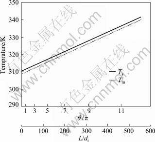
Fig. 7 Mean fluid and surface temperature distributions along downstream direction ( =0.872 kg/s)
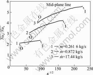
Fig. 8 Comparison of Nu ratio
The line has linear distribution with square root of the Dean number (κ1/2), which indicates proportionality with Re or the flow velocity. This indicates that for the spiral coiled tube is found to have the same proportionality characteristics with the helical coiled tube as reported in the literature.
4 Conclusions
1) The cross sectional velocity distributions of the main flow and the secondary flow show similar trends for both of the spiral and helical coiled tubes.
2) The friction factor and Nu follow similar proportions with Re and square root of the Dean number (κ1/2) in both of the coiled tubes.
3) For both design parameters of the friction factor and Nu, Re is found to have stronger effect compared to the curvature ratio.
Nomenclature
References
[1] DEAN W R. Note on the motion of fluid in a curved pipe [J]. Philosophical Magazine, 1927, 4: 208-223.
[2] JANSSEN L A M, HOOGENDOORN C J. Laminar convective heat transfer in helical coiled tubes [J]. International Journal of Heat and Mass Transfer, 1978, 21: 1197-1206.
[3] PRASAD B V S S S, DAS D H, PRABHAKAR A K. Pressure drop, heat transfer and performance of a helically coiled tubular exchanger [J]. Heat Recovery Systems and CHP, 1989, 9: 249-256.
[4] ALI S. Pressure drop correlations for flow through regular helical coil tubes [J]. Fluid Dynamics Research, 2001, 28: 295-310.
[5] PRABHANJAN D G, RAGBAVAN G S V, RENNIE T J. Comparison of heat transfer rates between a straight tube heat exchanger and a helically coiled heat exchanger [J]. International Communications in Heat and Mass Transfer, 2002, 29: 185-191.
[6] ROSE J W. Heat-transfer coefficients Wilson plot and accuracy of thermal measurements [J]. Experimental Thermal and Fluid Science, 2004, 28: 77-86.
[7] NAPHON P. Thermal performance and pressure drop of the helical-coil heat exchangers with and without helically crimped fins [J]. International Communications in Heat and Mass Transfer, 2007, 34: 321-330.
[8] NAPHON P, WONGWISES S. A review of flow and heat transfer characteristics in curved tubes [J]. Renewable and Sustainable Energy Reviews, 2006, 10: 463-490.
[9] SHOKOUHMAND H, SALIMPOUR M R, AKHAVAN- BEHABADI M A. Experimental investigation of shell and coiled tube heat exchangers using Wilson plots [J]. International Communications in Heat and Mass Transfer, 2008, 35: 84-92.
[10] SANTINI L, CIONCOLINI A, LOMBARDI C, RICOTTI M. Two-phase pressure drops in a helically coiled steam generator [J]. International Journal of Heat and Mass Transfer, 2008, 51: 4926-4939.
[11] JAYAKUMAR J S, MAHAJANI S M, MANDAL J C, VIJAYAN P K, BHOI R. Experimental and CFD estimation of heat transfer in helically coiled heat exchangers [J]. Chemical Engineering Research and Design, 2008, 86: 221-232.
[12] GHORBANI N, HESSAM TAHERIAN H, GORJI M, MIRGOLBABAEI H. An experimental study of thermal performance of shell-and-coil heat exchangers [J]. International Communications in Heat and Mass Transfer, 2010, 37: 775-781.
[13] NAPHON P, WONGWISES S. Experimental and theoretical investigation of the heat transfer characteristics and performance of a spiral-coil heat exchanger under dry-surface conditions [C]// Proceedings of 2nd International Conference on Heat Transfer, Fluid Mechanics, and Thermodynamics. Victoria Falls, Zambia, 2003: 24- 26.
[14] NAPHON P, SUWAGRAI J. Effect of curvature ratios on the heat transfer and flow developments in the horizontal spirally coiled tubes [J]. International Journal of Heat and Mass Transfer, 2007, 50: 444-451.
[15] NAPHON P. Study on the heat transfer and flow characteristics in a spiral-coil tube [J]. International Communications in Heat and Mass Transfer, 2011, 38: 69-74.
[16] DRAVID A N, SMITH K A, MERRILL E, BRIAN P L T. Effect of secondary fluid on laminar flow heat transfer in helically coiled tubes [J]. AIChE Journal, 1971, 17: 1114-1122.
[17] PARTANKAR S V. Numerical heat transfer and fluid flow [M]. New York: McGraw_Hill, 1980: 1-78.
[18] CFX v12 Solver theory guide [M]. Southpoint: ANSYS Inc, Southpoint, 2009: 1-169.
[19] OLSON D E, SYNDER B. The upstream scale of flow development in curved circular pipes [J]. Journal of Fluid Mechanics, 1985, 150: 139-158.
(Edited DENG Lü-xiang)
Foundation item: Work supported by the Second Stage of Brain Korea 21 Projects, Korea
Received date: 2011-05-24; Accepted date: 2011-10-10
Corresponding author: CHOI Hoon-ki, Associate professor, PhD; Tel: +82-55-213-3628; E-mail: hkchoi@changwon.ac.kr


