Article ID: 1003-6326(2005)03-0706-05
Copper electrodeposition from cuprous chloride
solutions containing lead, zinc or iron ions
M.Tchoumou1, M.Roynette Ehics2
(1. Faculty of Science, Marien Ngouabi University, BP 69 Brazzaville, Congo;
2. Laboratory of Applied Electrochemistry, Louis Pasteur University,
Blaise Pascal Street, 67000 Strasbourg, France)
Abstract: Cuprous chloride hydrochloric acid solutions were electrolysed in a two compartments cell without agitation for copper extraction. It is found that the current density affects the colour and the size of copper deposits. During electrodeposition of copper from cuprous solution in the presence of various concentrations of lead, zinc or iron ions at different current densities, it is observed that lead is codeposited with copper by increasing current density. In all experiments, the current efficiency for the copper deposition reaction fluctuates between 88.50% and 95.50%.
Key words: electrodeposition; codeposition; current efficiency; cuprous chloride solution CLC
number: TF803.27 Document code: A
1 INTRODUCTION
The electrodeposition of copper was largely studied from cupric solutions in sulphate electrolyte[1-3]. Some studies were carried out in chloride electrolyte[4, 5]. For hydrometallurgical chloride processes for treating copper ores, the others insist to leach the sulphides such as chalcopyrite, galena or blend by cupric chloride solution and the leaching solution resulted containing cuprous chloride and several impurities such as lead, zinc or iron at various concentrations can be electrolysed for the recovery of copper[6-8]. Some authors indicated that cuprous solutions electrolysis is advantageous because the energy required can be decreased by a factor of two compared to conventional cupric solution electrodeposition[5].
However, many precautions were taken to avoid the oxidation of cuprous to cupric ions. Before electrolysis, all cuprous chloride solutions were treated by metallic copper for reducing cupric to cuprous ion and the feed of electrolytic cell by cuprous solution was carried out under the nitrogen. The solutions were then analysed before and after electrolysis to determine the quantity of each metal deposited.
2 EXPERIMENTAL
2.1 Electrolyte composition
The electrolyte prepared with laboratory reagents contained CuCl 0.5mol/L, NaCl 3.5mol/L and HCl 1mol/L. The other electrolytes for codeposition study contained CuCl 0.5mol/L, NaCl 3.5mol/L, HCl 1mol/L and PbCl2, ZnCl2 or (NH4)2Fe(SO4)2・6H2O in the concentration range of 10-2-10-1mol/L.
To avoid the oxidation of cuprous to cupric ions, the system used for electrolyte preparation contained:
1) The reservoir containing cuprous chloride solution, the stirring bar and metallic copper to reduce cupric ion according to the reaction
Cu2++Cu[FY]2Cu+(1)
2) The magnetic stirrer;
3) The system of passage of nitrogen to maintain copper in the cuprous state.
After the disappearance of the colour indicating complete cupric ion consumption, the feed of electrolytic was carried out in electrolyte by gravity (Fig.1).
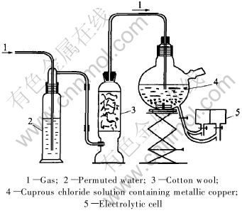
Fig.1 System for reduction of cupric ions and feed of electrolytic cell
2.2 Electrical system and electrolytic cell
All experiments were carried out using an intentiostatic system with the electrical system containing:
1) The tension generator to impose the electrolysis current density;
2) The electronic millivoltmeter to measure the work electrode potential EET/ER;
3) The multimeter to measure the potential in the electrolysis circuit EET/CE;
4) The milliampermeter to measure the electrolysis current density;
5) The electrolytic cell (Fig.2).

Fig.2 Electrical system for cuprous chloride solution electrolysis
The electrolytic cell was a cylindrical form, constructed with the Plexiglas and consisted of two compartments that were separated by a diaphragm. The anodic and cathodic compartments were assembled by screwing with toric join.
In each compartment of the electrolytic cell there is placed:
1) low, a tap with three ways to allow the filling or to empty the compartment;
2) up, an orifice for the gas discharge.
The cathode is constituted by a copper disk of 3cm diameter and the anode is a carbon disk of the same diameter.
The electrolyte volume in each compartment is 22mL (Fig.3).
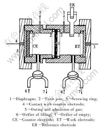
Fig.3 Electrolytic cell for electrolysis of cuprous chloride solution
3 RESULTS AND DISCUSSION
3.1 Influence of current density on quality of deposits obtained from solution of cuprous chloride
The electrodeposition of metals is influenced by some factors as current density, solution composition, presence of additives or others ions, pH and temperature[9-11]. To prevent interference during electrolysis, no additives were used in the electrolyte preparation. To avoid secondary reactions, it was found that cuprous concentration in the solution do not go down a certain degree of transformation; accordingly, all experiments were carried out with the charge of 225C which corresponds to the deposition of the quarter of the total quantity of the copper in the solution. This charge was obtained by circulation of a current I during a time t. The current efficiency for the copper deposition reaction was determined by the relation:
R=number of equivalent of copper deposited/number of faradays of electricity used
According to the charge and the characteristics of electrolytic cell, the values of current densities used were 17.7, 35.4 and 70.7mA/cm2, the corresponding electrolysis duration was respectively 30, 15 and 7.5min.
When the electrolysis begins, in the cathodic compartment, the solution remains colourless, a variable colour deposit is formed on the electrode, a gas is discharged for the high value of current density. The electrochemical reactions can be written as
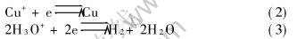
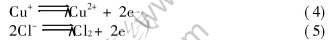
In the anodic compartment, the colour of the solution changes to green, a gas is discharged for the high value of current density. The electrochemical reactions can be written as
It was observed that the quality of copper deposits changes with the value of current density.
1) For J=17.7mA/cm2, the copper deposit was smooth, colour orange and adhered on the electrode. This deposit can not be detached.
2) For J=35.4mA/cm2, the copper deposit was large grains, colour orange, very brilliant and easily detached on the electrode. This deposit was recovered by filtration.
3) For J=70.7mA/cm2, the copper deposit was very fine grains, colour dark, and easily detached on the electrode, but in filtration, the deposit move in the pore of the filter and total recovery of copper was difficult.
This observation on the current density influence on the quality of metals deposits confirms those of Olsen et al[12].
In order to make clear the current density limit that the adherent deposits become no adherents, some experiments were carried out with the intermediate values of current density from 20 to 33mA/cm2. Those experiments indicated that the limit current density to obtain the deposits which can be easily detached is 30mA/cm2.
Table 1 lists the results of same experiments carried out at different values of current density. Each solution was analysed before and after electrolysis by pulse polarography and by flame absorption spectrometry to determine the quantity of copper in the solution.
3.2 Electrolysis of cuprous chloride solutions in presence of lead, zinc or iron ions
The cuprous chloride solutions containing lead, zinc or iron ions in the concentration range 10-2 to 10-1mol/L were electrolysed at different current densities to know that which metals were deposited with copper. After treating the solution by copper metallic for reducing cupric to cuprous ions, each solution was analysed before and after electrolysis by pulse polarography and by flame atomic spectrometry. The difference of the concentration of a metal allows to conclude the codeposition of this metal with copper. It was found that the lead was the same metal whose concentration decreased, only if the current density was 70.7mA/cm2. Since the result was obtained by difference of two numbers near enough, the conclusion is not accurate. The acceptable method to confirm that the metal is codeposited with copper consisted of dissolving the no adherent deposits with nitric acid and analysis of the resulting solution by pulse polarography and by flame atomic spectrometry.
Tables 2, 3 and 4 show the results obtained when the current density was 70.7mA/cm2. Those results are indicated that the concentration of lead is lightly decreased after electrolysis of a solution containing CuCl and PbCl2 at 70.7mA/cm2.
Figs.4 and 5 show the polarogram of solution of dissolution of deposit obtained respectively from CuCl+PbCl2 and CuCl+ZnCl2 solutions.
Fig.4 indicates clearly the presence of lead
Table 1 Copper electrodeposition from cuprous chloride solution
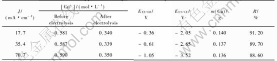
Table 2 Copper electrodepositon from solution containing CuCl and PbCl2 at 70.7mA/cm2
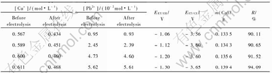
Table 3 Copper electrodeposition from solution containing CuCl and ZnCl2 at 70.7mA/cm2
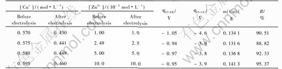
Table 4 Copper electrodeposition from solution containing CuCl and
(NH4)2Fe(SO4)2・6H2O at 70.7mA/cm2
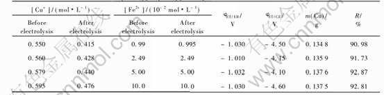
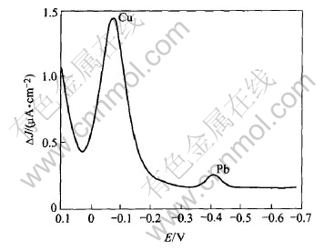
Fig.4 Polarogram of solution of dissolution of deposit obtained from CuCl and PbCl2 solution at 70.7mA/cm2
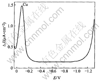
Fig.5 Polarogram of solution of dissolution of deposit obtained from CuCl and ZnCl2 solution at 70.7mA/cm2
in the deposit while Fig.5 shows that zinc is not present in the deposit. We then determined the quantity of lead in the deposit when increasing the initial concentration of Pb2+ in the solution, and the duration of electrolysis at 70.7mA/cm2. The corresponding Figs.6 and 7 indicate that the lead is deposited even at the low initial concentration of Pb2+ in the solution, and that this deposit is not uniform but its quantity is increased with the duration of electrolysis.
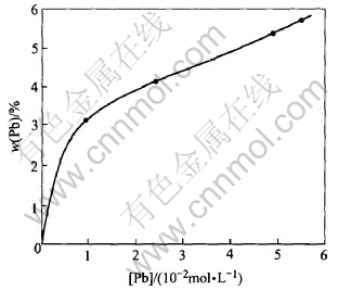
Fig.6 Content of lead in deposit as function of initial concentration of Pb2+ at 70.7mA/cm2
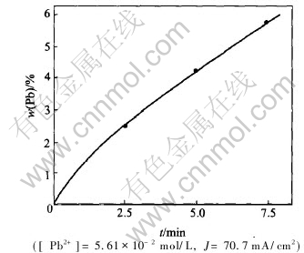
Fig.7 Content of lead in deposit as function of duration of electrolysis
For the experiments carried out at 70.7mA/cm2, we determined the fraction of lead effectively deposited, and the content of lead in the deposit as function of the initial concentration of Pb2+.
The results obtained show that the content of lead in the deposit increases while the fraction of lead effectively used for the deposit decreases when the initial concentration of Pb2+ in the solution increases.
This observation can be explained by the relative decreasing of the concentration of Cu+ which is more important than that of Pb2+.
For the adherent deposits, the examination of the cathode by the CASTAING microprobe indicated that lead, zinc, or iron was not codeposited with copper.
Muresan et al[13] indicated that the zinc is not deposited with copper during the study of the effect of the zinc ion on the copper electrolysis in sulphuric media.
4 CONCLUSIONS
1) The electrolysis of cuprous chloride solutions at different current densities shows that the deposits have different morphologies and adherence quality. In the presence of various concentration of lead, zinc or iron ions, it is found that the same metal which is codeposited with copper is the lead, when the current density becomes superior to 45mA/cm2.
2) The lead content in the deposit increases with the initial concentration of Pb2+ in the solution and with the duration of electrolysis.
3) In all experiences, the current efficiency for the copper deposition reaction is high and varies from 88% to 95%.
REFERENCES
[1]Panda B, Das S C. Electrowining of copper from sulfate electrolyte in presence of sulfurous acid[J]. Hydrometallurgy, 2001, 59 (1): 57-67.
[2]Clifford A H. The encyclopedia of Electrochemistry[M]. Rheinhold Publishing Corporation, 1964.
[3]Popov K I, Pavlovic M G, Stojilkovic E R, et al. The current density distribution on stationary wire electrodes during copper and lead electrodeposition[J]. Hydromellurgy, 1997, 46 (3): 321-336.
[4]Kekesi T, Isshiki M. Electrodeposition of copper from pure cupric chloride hydrochloric acid solutions[J]. J Appl Electroch, 1997, 27(8): 982- 990.
[5]Mackinnon D J, Brannen J M, Mc Millan R S. Factors affecting the structure of copper deposits electrowon from aqueous chloride electrolyte[J]. J Appl Electrochem, 1985, 15: 649-658.
[6]Cathro K J. Trends in Electrochem[M]. Edited by Bockris J O M. Plenum Press, 1977.
[7]Guy S, Broadbent C P, Lawson G J, et al. Cupric chloride leaching of a complex copper/zinc/lead ore[J]. Hydrometallurgy, 1983, 10: 243-255.
[8]Dutizac J E. The leaching of sulphide minerals in chloride media[J]. Hydrometallurgy, 1992, 29(1): 1-45.
[9]ZHENG Guo-qu, ZHENG Li-feng, CAO Hua-zhen, et al. Nickel electrodeposition from leaching solution containing ammonia and chloride[J]. Trans Nonferrous Met Soc China, 2003, 13(1): 217.
[10]Raessi K, Saathi A, Golozar M A. Effect of nucleation mode on the morphology and texture of electrodeposited zinc[J]. J Appl Electrochem, 2003, 33(7): 635-642.
[11]Tsai W C, Wan C C, Wang Y Y. Mechanism of copper electrodeposition by pulse current and its relation current efficiency[J]. J Appl Electrochem, 2002, 32(12): 1371-1378.
[12]Olsen R S, Yee D H, Hundely G L. Chlorination process of the recovery of copper from chalcopyrite[J]. AIME Transactions, 1973, 254: 301-305.
[13]Muresan L, Nicoara A, Varvara S, et al. Influence of Zn2+ ions on copper electrowinning from sulfate electrolytes[J]. J Appl Electrochem, 1999, 29: 723-731.
(Edited by YUAN Sai-qian)
Received date: 2004-09-21; Accepted date: 2005-01-27
Correspondence: M.Tchoumou, PhD; Tel: (242) 668-64-91; E-mail: tchoumoutafel@yahoo.fr

