��������AA5754��AA6061���Ͻ����ѧ���ܺ�����֯�ݻ�
��Դ�ڿ����й���ɫ����ѧ��(Ӣ�İ�)2020���1��
�������ߣ�Ghulam HUSSAIN Muhammad ILYAS B. B. LEMOPI ISIDORE Wasim A. KHAN
����ҳ�룺51 - 64
�ؼ��ʣ����㽥�����Σ���ѧ���ܣ�����֯�ݻ������Ͻ𣻳��νǣ����β���
Key words��single point incremental forming; mechanical properties; microstructure evolution; aluminum alloy; wall angle; forming parameter
ժ Ҫ���õ��㽥������(SPIF)�ӹ��������Ͻ�(AA5754��AA6061)���ҷ������ϳ��κ����ѧ���ܺ�����֯�ݻ����о����β����������ν� (35��~55��)�������ٶ�(1~4 m/min)������ת��(50~1000 r/min)����(���͡�Һѹ��)�ȵ�Ӱ�졣�ֱ�ͨ�����������ѧ��������������SPIFǰ�����ѧ���ܺ�����֯�ݻ���������������νǡ������ٶȺ�����ת�ٵ�������AA5754�Ͻ��о�����AA6061�Ͻ��еڶ��ྦྷ���쳤��AA5754��AA6061���Ͻ�ļ�����ǿ�ȷֱ����10%��8%��AA5754���Ͻ����չ�Դ�22.9%�½���12%��AA6061���Ͻ����չ�Դ�16%�½���10.7%��������Ч������ѧ���ܶ�����������С����ϣ�SPIF�����ܸ������Ͻ������֯�������ǿ�ȣ�����������չ�ԡ�
Abstract: This study performs single point incremental forming (SPIF) on two aluminum alloys (i.e. AA5754 and AA6061), and analyzes their post forming mechanical properties and microstructure evolution. The forming parameters namely wall angle (35��-55��), feed rate (1-4 m/min), spindle rotational speed (50-1000 r/min), and lubricant (grease and hydraulic oil) are varied to probe detailed processing effects. The pre- and post-SPIF mechanical properties and microstructures are characterized by conducting tensile tests and optical microscopy, respectively. It is shown that an increase in the wall angle, feed rate and rotational speed causes microscopic variations in the alloys such that the grains of AA5754 and the second phase particles of AA6061 elongate. As a result, the ultimate tensile strength of the formed parts is increased by 10% for AA5754 and by 8% for AA6061. And, the ductility of AA5754 is decreased from 22.9% to 12% and that of AA6061 is decreased from 16% to 10.7%. Regarding the lubricant effect, it is shown that the mechanical properties remain insensitive to the type of lubricant employed. These results indicate that SPIF processing modifies the microstructure of Al alloys in a way to enhance the strength at the cost of ductility.
Trans. Nonferrous Met. Soc. China 30(2020) 51-64
Ghulam HUSSAIN1, Muhammad ILYAS1, B. B. LEMOPI ISIDORE2, Wasim A. KHAN1
1. Faculty of Mechanical Engineering, GIK Institute of Engineering Sciences and Technology, Topi 23460, Pakistan;
2. Chair of Mechanical Design and Manufacturing, Brandenburg University of Technology (BTU), Cottbus-Senftenberg 03013, Germany
Received 6 February 2019; accepted 26 November 2019
Abstract: This study performs single point incremental forming (SPIF) on two aluminum alloys (i.e. AA5754 and AA6061), and analyzes their post forming mechanical properties and microstructure evolution. The forming parameters namely wall angle (35��-55��), feed rate (1-4 m/min), spindle rotational speed (50-1000 r/min), and lubricant (grease and hydraulic oil) are varied to probe detailed processing effects. The pre- and post-SPIF mechanical properties and microstructures are characterized by conducting tensile tests and optical microscopy, respectively. It is shown that an increase in the wall angle, feed rate and rotational speed causes microscopic variations in the alloys such that the grains of AA5754 and the second phase particles of AA6061 elongate. As a result, the ultimate tensile strength of the formed parts is increased by 10% for AA5754 and by 8% for AA6061. And, the ductility of AA5754 is decreased from 22.9% to 12% and that of AA6061 is decreased from 16% to 10.7%. Regarding the lubricant effect, it is shown that the mechanical properties remain insensitive to the type of lubricant employed. These results indicate that SPIF processing modifies the microstructure of Al alloys in a way to enhance the strength at the cost of ductility.
Key words: single point incremental forming; mechanical properties; microstructure evolution; aluminum alloy; wall angle; forming parameter
1 Introduction
Single point incremental forming (SPIF) process employs a point contact method, and incrementally imparts the desired shape to a blank sheet. In SPIF the need of specialized tooling is eliminated, which results in significant advantages, such as higher flexibility, lower lead time and smaller initial cost. Therefore, this process is gaining popularity over conventional forming process for batch production and rapid prototyping. The SPIF process has received considerable attention in manufacturing associated with the automotive, aerospace and biomedical applications [1,2].
A predecessor concept to SPIF process was patented by LESZAK [3] in 1967 and academic research on the process sprouted in early 1990s [4]. In the past two decades, considerable research has been targeted to explain the higher formability by studying the deformation mechanics of SPIF [5-11]. However, further research is required to establish the wide acceptability of process in manufacturing industry.
The deformation and mechanical properties of sheet metals have been found to be interrelated. JESWIET et al [12] determined mechanical constants for AA3003 sheet and found that the tensile strength increased while tensile fracture strain decreased with increasing the forming angle in the SPIF process. Similarly, uniaxial tension tests performed by LI et al [13], on components formed through SPIF, demonstrated that the elongation of material decreased but the strength increased owing to work hardening effect during SPIF process. ULACIA et al [14] studied the influence of increased temperature upon mechanical properties and microstructure of magnesium (Mg) alloys during incremental sheet forming (ISF). They observed a twinned structure, and comparison of ISF with uniaxial stretching revealed that ISF generated more twins. OTSU et al [15] observed that work hardening caused the hardness of formed sheets to increase, while elongation at fracture was slightly less than that of the as-received sheet of AA2017.
Although, considerable attention has been paid to deformation mechanics and fracture initiation in the past [5-7,16,17], the evolution of micro- structure and associated mechanical properties achievable in a forming process is also an important research direction because these attributes determine the service performance and life of a formed component. Improved surface quality and higher mechanical properties were accomplished due to the refined and defects-free uniform microstructure achieved during double-control forming of AM50A alloys [18]. The strength and ductility of cryo-rolled AA6061 have been demonstrated to be enhanced due to formation of ultrafine grains resulting from dislocation tangling [19]. CHEN et al [20] found that induced stress during age forming causes the grains of 2A12 aluminum alloy to squeeze and elongate, while tensile properties and facture toughness are reduced. YANG et al [21] observed elongated-ring-like diffraction patterns indicating significant refinement of initial coarse grains with very high dislocation density for 1050 commercially pure aluminum alloy deformed under high strain rates. JAWALE et al [22] investigated the microstructure evolution of copper sheets in SPIF under various lubrication conditions. They concluded that grain size remained independent of lubrication conditions. MOHAMMADI et al [23] performed laser-assisted SPIF (LASPIF) on AA2024-T3 sheet. The microstructure analysis revealed that low angle grain boundaries were converted into high angle grain boundaries and particle/matrix interface decohesion was responsible for fracture during LASPIF.
Very recently, the microstructure evolution of AA6061 material due to SPIF has been investigated by BARNWAL et al [24]. They reported that AA6061 offered the highest resistance to deformation when forming was carried out at 45�� to rolling direction, and this in turn led to the least grain elongation and visible texture development. Furthermore, they attributed this higher resistance in 45�� to Taylor factor which is higher in 45�� direction as compared with rolling and transverse directions. SHRIVASTAVA and TANDON [25] have reported the microstructure and texture based analysis of SPIF of AA1050 sheet under SPIF. They observed significant amount of localized slip bands in thickness direction.
The AA5754 and AA6061 aluminum alloys have been found to have a wide range of applications in the automotive and aerospace sectors owing to the fact that these materials exhibit good corrosion resistance, reasonably high specific strength and adequate formability. Very limited efforts have been made on microstructural evolution and mechanical properties in SPIF of aluminum alloys in general and the aforementioned two alloys in particular. The relevant information is also missing with particular reference to the effects of process parameters. Therefore, it is necessary to make efforts in this direction so that the generated knowledge can be used as a guideline in the design of components to be produced through SPIF.
In this study, a series of SPIF experiments were conducted to know the effect of various parameters on the microstructure and mechanical properties of AA5754 and AA6061 aluminum alloys. The considered parameters included wall angle, feed rate, spindle rotational speed and lubrication. The resulting changes in the mechanical properties and microstructure were quantified through microscopic examinations.
2 Experimental
2.1 Experimental setup
The forming process was carried out on a 3-axis milling machine, as shown in Fig. 1(a) [26]. A 14 mm diameter hemispherical head high speed steel (HSS) tool hardened up to HRC 55, seen Fig. 1(b) [26], was employed. The hemispherical head reduces friction between the blank and the forming tool. Tool diameter was held constant during this study. Furthermore, a helical tool path with a constant vertical step was employed. The schematic representation of tool path is shown in Fig. 1(c).
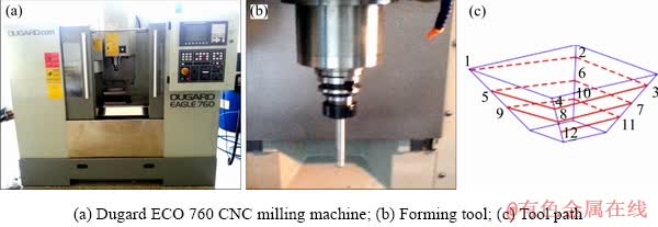
Fig. 1 Experimental setup [26] (1-12 stand for linear movement of the tool point 1 to 2, 2 to 3, 3 to 4 and so on)
2.2 Materials
Magnesium based aluminum (Al) alloys (AA5754-H22 and AA6061-T6) in sheets of 1.5 mm, have been selected for the current study. In the following paragraphs, we shall refer to these materials as AA5754 and AA6061, dropping the heat treatment designations for brevity. AA5754 is magnesium (Mg) based, while AA6061 is Mg and silicon (Si) based alloy. AA5754 and AA6061 both show improved corrosion resistance, better weldability and higher formability as compared with pure aluminum. The chemical compositions of both alloys are presented in Table 1.
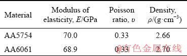
Mechanical properties of both materials are given in Table 2.
Table 1 Chemical compositions of AA575 and AA6061 (wt.%)
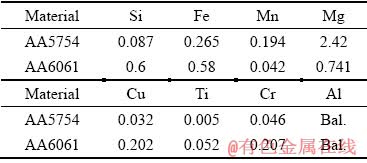
Table 2 Mechanical properties of materials
2.3 Design of experiments
The test plan to reveal relationship of microstructure evolution with forming wall angle, feed rate and spindle rotational speed are summarized in Table 3. The forming angle is varied from a steeper angle of 55�� to a shallower angle of 35�� with an intermediate value of 45��. Forming, at even higher angels, leads to fracture and one cannot extract tensile samples to analyze mechanical strength at the steeper angle. In addition, the feed rate is altered from 1 to 4 m/min for both materials. Furthermore, the spindle rotational speed is also varied (from 50 to 1000 r/min) and the influence of all these combinations on the surface quality and microstructure of final product is analyzed. The reason underlying alteration of feed rate and rotational speed is that these two parameters affect the heating and strain hardening.
Table 3 Test plan of AA6061 and AA5754
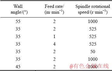
Figure 2 shows some of the formed parts at different wall angles. The computer aided design (CAD) models used for tool-path generation are shown in Figs. 2(a, c, e). While the actual formed parts are shown in Figs. 2(b, d, f). It is to be noted that two runs for each test were performed.
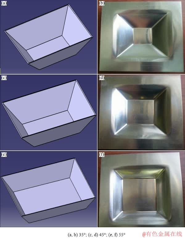
Fig. 2 CAD (a, c, e) and actual (b, d, f) formed parts at different wall angles
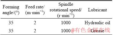
Proper lubrication is essential to obtain smooth surface and avoid wear of forming tool and blank sheet. Therefore, AA6061 was formed using LG Hydro HD liquid lubrication, only. However, in order to investigate the effects of lubricants, AA5754 was formed by using two different lubricants, namely Lithium Complex EP2 grease and LG Hydro HD liquid. The effect of different lubricants on AA5754 is summarized in Table 4.
2.4 Experimental methodology
Mechanical properties of parent (blank) sheet and formed parts were obtained by performing tension testing on universal testing machine, Instron 3385H. Sub-sized tensile test specimens were prepared in accordance with ASTM standard E8M [27] by using a wire cut machine. The tensile tests were performed approximately two weeks after the SPIF. The specimens for revealing the microstructure were etched using following etchants: Poulton reagent (12 mL HCl + 6 mL HNO3 + 1 mL HF + 1 mL DI water) for AA6061 and 50 mL Poulton reagent + 40 mL acid chromic + 10 mL H2O for AA5754 (as described in the ASM handbook [28]).
Table 4 Effect of different lubricants on AA5754
3 Results and discussion
3.1 Effects of wall angle
3.1.1 Effect of wall angle on mechanical properties
The influence of wall angle on mechanical properties was investigated by realizing 35��, 45�� and 55�� pyramids by SPIF process. The remaining parameters such as feed rate, spindle rotational speed and lubricant were kept identical. Figure 3 shows plots of ultimate tensile strength (UTS) and elongation for AA5754 and AA6061. Sudden rise in UTS, as compared with base material, is observed for both materials when formed at 35��. The UTS of AA6061 further rises at higher angles of 45�� and 55�� while the same becomes stagnant for AA5754 at similar angles. This behavior can be explained by the fact that higher amount of cold working entails higher work hardening and thus results in higher strength of the metal.
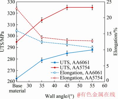
Fig. 3 Effect of wall angle on ultimate tensile strength and elongation of two materials
The elongation as a function of forming angle is also plotted in Fig. 3. It is evident that AA5754 is more ductile as compared with AA6061. Forming at 35�� causes a significant reduction of elongation of both materials after forming. The elongation of AA5754 drops from 22.9% to 13.9% and for AA6061 this drop takes place from 16% to 12.5%. The elongation at failure keeps on dropping and at a wall angle of 55�� it has decreased to 12.8% and 10.7% for AA5754 and AA6061, respectively. Similar values of UTS and ductility have been reported by BARNWAL et al [24] for AA6061.
3.1.2 Effect of wall angle on microstructure
The optical microscope images of AA5754, base metal and formed parts, are shown in Fig. 4. The average grain diameter for base material is found to be 103 ��m, see Fig. 4(a). The SPIF at 35�� causes this diameter to increase to 121 ��m, as evident from Fig. 4(b). This is to be noted that projected area is measured through thickness measurements are not taken.
The influence of wall angle on the average grain diameter and grain area of AA5754 have been summarized in Table 5 [29]. It is evident that an increase in wall angle causes the projected area (a measure of aspect ratio) of the grain to increase. The mean linear intercept length of grain shows an increase of 30.4% with respect to the base value.
Figure 5 shows the plot of UTS as a function of mean linear intercept length at different wall angles. The value of UTS increases with an increase in length of grains and a second order polynomial fit can approximate this rise. In fact, an increase in the length of grains is accompanied by reduction in the thickness of grains (which could not be measured because projected surface was examined in this study). Therefore, it is possible to say that the strength increase is due to reduction in grain thickness; a finding consistent with Hall-Petch relationship [30,31].
The following discussion is aimed at exploring influence of wall angle on the second phase particles in AA6061. In Fig. 6, very distinct black particles can be distinguished. The AA6061 sheet is chemically designated as AlMgSiCu [28], and these black particles can be identified as Mg2Si. The microscopic image of AA6061 base metal, i.e. before deformation, is presented in Fig. 6(a). The even distribution of Mg2Si particles throughout the parent sheet is evident. As the SPIF is carried out at a wall angle of 35��, see Fig. 6(b), these second phase particles appear to merge. Similar behavior is observed in Fig. 6(c), formed at 45��, and it is further noted that the size of these particles is progressively greater than that noted for base material and part formed at 35��.
Finally, the highest amount of joining of second phase particles is confirmed for forming angle of 55��, referring to Fig. 6(d). It is noticed from Figs. 6(b, c, d) that inclusions in these samples got elongated and coalesced due to the tool action. A quantitative summary of these results is presented in Table 6, which exhibits the maximum sizes (length and width) of the second phase particles
against each forming angle. It can be appreciated that the SPIF tool caused the length of the Mg2Si particles to increase and stretch these particles along forming direction. Hence, it can be said that the distortion of these particles during forming leads to the increase in the maximum length of the particles from 783 to 4565 ��m which belongs to the highest wall angle in this experiment.
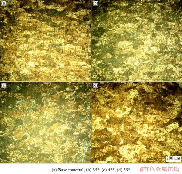
Fig. 4 Microscopic images of AA5754 realized at different wall angles
Table 5 Influence of wall angle on average grain size of AA5754 (avg. deviation=��1 ��m)
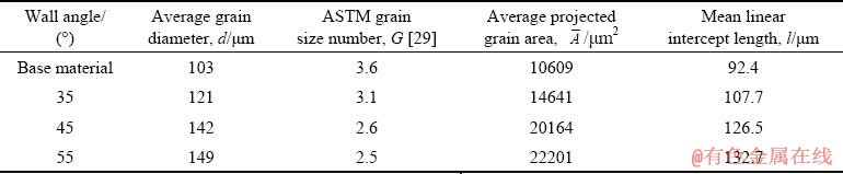
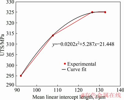
Fig. 5 Hall-Petch relationship observed at different wall angles
Deformation in metal forming occurs due to motion of dislocations [32]. The second phase particles, if any, reside themselves at low energy sites near the dislocations. While forming dislocations move and pile up whereby increasing the strength of the materials. The agglomeration found in Fig. 6 indicates that the second phase particles travel along with dislocations and pile up in a similar pattern. This is observed from Fig. 6 that the degree of agglomeration increases with increasing the angle. This seems to be rational because dislocation density and pile-up increase with increasing the forming angle (i.e. applied strain).
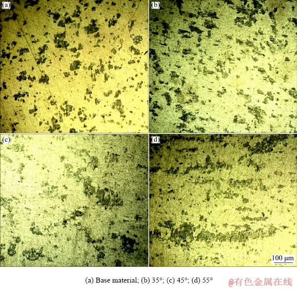
Fig. 6 Microscopic images of AA6061 at different wall angles
Table 6 Mean length and width of the second phase (Mg2Si) particles in AA6061 (avg. deviation=��6 ��m) formed at various angles

3.2 Effects of feed rate
3.2.1 Effect of feed rate on mechanical properties
The influence of feed rate on AA5754 and AA6061 was investigated by forming the pyramids at three different feed rates, i.e. 1, 2 and 4 m/min. Lubricant, wall angle and spindle rotation speed were kept constant. The specimens extracted prior to and after forming demonstrate that AA5754 exhibits higher strength as compared with AA6061 (see Fig. 7). It is further noted that both materials depict higher strength with increase in feed rate. The rate of increase in strength for both materials is maximum for the parts formed at 1 m/min (Fig. 7). Subsequently, although strength keeps on rising, the rate of increase is gradual for parts formed at 2 and 4 m/min, respectively.
Elongation at failure as a function of feed rate is also plotted in Fig. 7. As seen in the previous paragraphs, it is normal to expect reduction in elongation (at failure) after deformation by SPIF due to work hardening. For AA5754 and AA6061, higher reduction in ductility takes place for AA5754. Here, the elongation at failure chutes down from 22.9%, as observed for base metal, to 13% for the part formed at 1 m/min. A similar trend is observed for AA6061, where this drop occurs from 16% to 12.9%. Both AA5754 and AA6061 demonstrate that the elongation at failure remains approximately constant for feed rates from 1 to 4 m/min. Therefore, it can be concluded that feed rate does not influence the elongation (ductility) of the parts formed via SPIF.

Fig. 7 Effect of feed rate on ultimate tensile strength and elongation of AA5754 and AA6061
3.2.2 Effect of feed rate on microstructure
The effect of feed rate on microstructure of parts formed by SPIF process was investigated. Figure 8 compares the optical microscope (OM) images of three different feed rates with that of the base material. It is evident in Fig. 8 that with higher feed rate, the average grain diameter of the specimens increases from 116 ��m corresponding to a feed rate of 1 m/min, Fig. 8(b), to 138 ��m, of which is formed with a feed rate of 4 m/min, Fig. 8(d).
Table 7 presents summary of influence of feed rate on average grain size of AA5754. The survey reveals that the average grain area increases with an increase of feed rate.
The ultimate tensile strength as a function of mean linear intercept length is plotted in Fig. 9. It can be seen that as the length of grains increases, the strength of parts is also increased. This further confirms that the strength increase is due to reduction in grain thickness; a finding consistent with Hall-Petch relationship [30,31].
Figure 10 presents OM images of AA6061 before and after forming. It is evident that the density of the second phase particles remains constant. The influence of feed rate manifests itself as joining of the second phase particles. With increasing feed rate more elongated particles are observed (Figs. 10(b, c, d)).
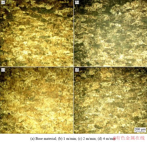
Fig. 8 Effect of feed rate on microstructure of AA5754
Table 7 Effect of feed rate on average grain size of AA5754 (avg. deviation=��1 ��m)
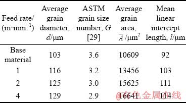
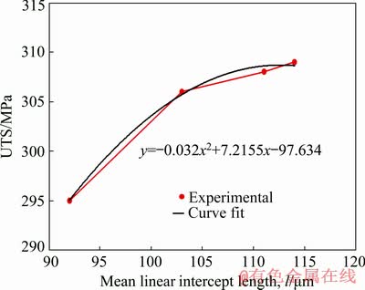
Fig. 9 UTS as function of mean linear intercept length
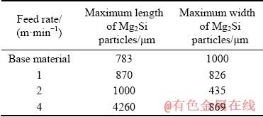
The effect of feed rate on joining of the second phase particles is summarized in Table 8. This table displays the maximum length and width of the Mg2Si particles. It is observed that with an increase in feed rate, the length of second phase particles increases while the width decreases. Furthermore, feed rate is an indicator of strain rate in ISF and it is a known fact in metal forming that dislocation density increases with increasing the strain rate [32]. As a result, the second phase particles�� residence at low energy site near the dislocations increases accordingly. The reason of the agglomeration of dislocations is discussed earlier in previous section concerning the influence of wall angle.
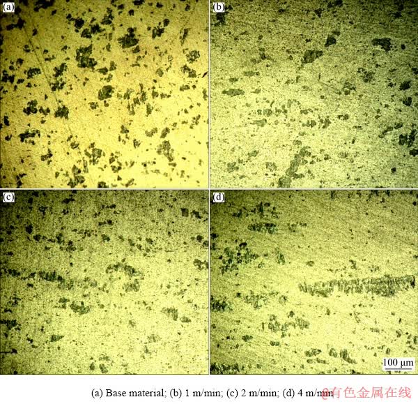
Fig. 10 OM images of AA6061 at different feed rates
Table 8 Effect of feed rate on maximum length and width of second phase (Mg2Si) particles in AA6061 (avg. deviation=��6 ��m)
3.3 Effects of spindle rotational speed
3.3.1 Effect of spindle rotational speed on mechanical properties
The effect of spindle rotational speed on UTS is shown in Fig. 11. The remaining forming parameters, such as forming wall angle, tool feed rate and lubrication type, were kept constant during these tests.
Figure 11 shows an increment in the UTS of both alloys, formed by the spindle rotating at 50 r/min, as compared with the UTS of the base material. However, the UTS values of both alloys exhibit insignificant change for spindle rotational speeds above 50 r/min and up to 1000 r/min. Therefore, it is concluded that the increase in spindle rotational speed has trivial effect on the strength of both materials formed by the SPIF process.
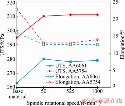
Fig. 11 Effects of spindle rotational speed on UST and elongation
Figure 11 also demonstrates the effect of spindle rotational speed on the ductility of the formed materials. It is evident that a significant reduction in ductility occurs, after the forming process, for both materials. This is typical attribute of metals, as the work hardening due to forming causes a reduction in the ductility. This further reinforces the conclusion that the effect of spindle rotational speed is negligible upon mechanical properties of formed materials.
3.3.2 Effect of spindle rotational speed on micro- structure
This paragraph focuses on the effect of spindle rotational speed on microstructures of base material and formed parts of AA5754. The average grain diameter for base material is 103 ��m, as measured from Fig. 12(a). A comparison among readings taken from images, as shown in Figs. 12(b, c, d), reveals that the part formed at a spindle speed of 525 r/min has greater average grain diameter, referring Fig. 12(c).
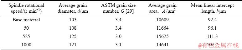
The grain sizes measured in base metal and the formed parts of AA5754 are summarized in Table 9. It is observed that the grain diameters and average grain areas are increased until 525 r/min and a small reduction is observed at the spindle rotational speed of 1000 r/min.
Figure 13 displays the effects of spindle rotational speed on the second phase particles in AA6061. Comparison of base material with the formed parts reveals that there is no significant effect on joining of Mg2Si particles after forming. The OM images further reveal that the spindle rotational speed in SPIF has the least effect on the elongation of the impurities in AA6061.
Furthermore, it is observed that a higher density of the Mg2Si particles is obtained in the part formed at 1000 r/min (see Fig. 13(d)). This indicates that the high spindle rotation speed might have caused the breaking of particles during forming.
A summary of the dimensional characteristics of the second phase (Mg2Si) particles in AA6061 is presented in Table 10. We can see that as the spindle rotational speed increases the length of Mg2Si increases and width decreases. When these results are combined with above presented in Fig. 13, an interesting conclusion is drawn. It appears that the second phase particles are divided into smaller sized particles and at the same time their density, as shown in the optical image, is increased. This is an important phenomenon, ultimately, leading to the increased strength of the formed parts.
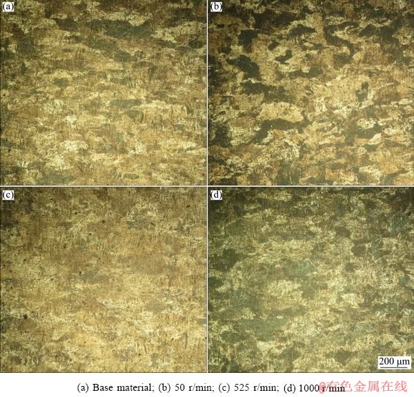
Fig. 12 OM images of AA5754 at different spindle rotational speeds
Table 9 Effect of spindle rotational speed on average grain size of AA5754 (avg. deviation=��1 ��m)
3.4 Effects of lubricant
3.4.1 Effect of lubricant on mechanical properties
The SPIF process is capable of generating immense heat locally, i.e. in the vicinity of tool and blank contact point, due to friction. Therefore, proper lubrication is an important concern during SPIF process. Hence, the study of the effect of hydraulic oil and lithium complex grease is of interest here. The effect of type of lubricant on strength and ductility is presented in Table 11 for AA5754 only. It is observed that the type of lubricant has a meager effect on UTS. Similarly, the ductility is also unaffected by the type of lubricant and quasi-identical numerical values of ductility are obtained.
3.4.2 Effect of lubricant on microstructure
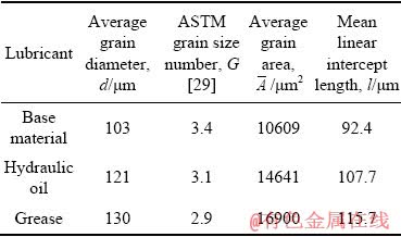
Table 12 summarizes the average grain area, ASTM grain size number and mean linear intercept length of base material (i.e. AA5754) and SPIF by employing two different types of lubricants, i.e. hydraulic oil and grease. The average grain diameter tends to slightly increase, i.e. from 121 to 130 ��m, but this increase in the grain size is not significant.
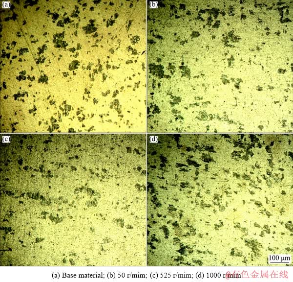
Fig. 13 OM images of the second phase particles in AA6061 at different spindle speeds
Table 10 Effect of spindle rotational speed on length and width of the second phase particles in AA6061 (avg. deviation=��6 ��m)
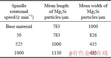
Table 11 Effect of lubricant on mechanical properties of AA5754
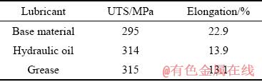
Table 12 Effect of lubricant on average grain size (avg. deviation=��1 ��m)
4 Conclusions
(1) The current study investigated the effects of ISF parameters on the microstructure and mechanical properties of two aluminum alloys, i.e. AA5754 and AA6061. The tests were performed by varying forming wall angle, feed rate, spindle rotational speed and lubricant.
(2) ISF processing affects the mechanical properties and microstructure evolution of AA5754 and AA6061 alloys. The principal effect is exhibited by the forming wall angle that increases the ultimate strength of both alloys (approximately 10% for each) as its value increases from 35�� to 55��. However, the increase in feed rate (from 1 to 4 m/min) and spindle rotational speed (from 50 to 1000 r/min) poses a trivial effect upon ultimate tensile strength. The increase in ultimate tensile strength is associated with a corresponding decrease in elongation of both alloys (maximum observed: 12.2% for AA5754 and 5.3% for AA6061).
(3) These properties are found to have correlation with the microstructure evolution during SPIF, particularly with grains and second phase particles. The grains and second phase particles both elongate as a result of ISF, thereby enhancing the strength and reducing the ductility of materials. These elongations are nearly 44% (maximum) for grains of AA5754 and approximately 500% (maximum) for second phase particles of AA6061.
(4) As for the effect of lubricants, the microstructure and mechanical properties both remain insensitive to the type of considered lubricants (grease and hydraulic oil).
References
[1] JESWIET J, MICARI F, HIRT G, BRAMLEY A, DUFLOU J, ALLWOOD J. Asymmetric single point incremental forming of sheet metal [J]. CIRP Annals-Manufacturing Technology, 2005, 54: 88-114. doi:10.1016/s0007-8506(07)60021-3.
[2] TALEB-ARAGHI B, GOTTMANN A, BAMBACH M, HIRT G, BERGWEILER G, DIETTRICH J, STEINERS M, SAEED-AKBERI A. Review on the development of a hybrid incremental sheet forming system for small batch sizes and individualized production [J]. Production Engineering, 2011, 5: 393-404. doi:10.1007/s11740-011-0325-y.
[3] LESZAK E. Apparatus and process for incremental dieless forming: USA patent, US3342051A1 [P]. 1967-09-19.
[4] ISEKI H, KUMON H. Forming limit of incremental sheet metal stretch forming using spherical rollers [J]. Journal of Japan Scociety for Technology of Plasticity, 1994, 35: 1336-1336.
[5] EMMENS W C, van den BOOGAARD A H. An overview of stabilizing deformation mechanisms in incremental sheet forming [J]. Journal of Materials Processing Technology, 2009, 209: 3688-3695. doi:10.1016/j.jmatprotec.2008. 10.003.
[6] JACKSON K, ALLWOOD J. The mechanics of incremental sheet forming [J]. Journal of Materials Processing Technology, 2009, 209: 1158�C1174. doi:10.1016/j.jmatprotec. 2008.03.025.
[7] LI Y, DANIEL W J T, MEEHAN P A. Deformation analysis in single-point incremental forming through finite element simulation [J]. The International Journal of Advanced Manufacturing Technology, 2017, 88: 255-267. doi:10. 1007/s00170-016-8727-9.
[8] SHIM M S, PARK J J. The formability of aluminum sheet in incremental forming [J]. Journal of Materials Processing Technology, 2001, 113: 654-658. doi:10.1016/s0924-0136 (01)00679-3.
[9] CAI G P, XING C W, JIANG Z H, ZHANG Z K. Sheet single point vibration incremental forming process simulation and analysis of process parameters [J]. Advanced Materials Research, 2012, 430-432: 74-78. doi:10.4028/www. scientific.net/amr.430-432.74.
[10] DEJARDIN S, GELIN J C, THIBAUD S. Experimental investigations and numerical analysis for improving knowledge of incremental sheet forming process for sheet metal parts [J]. Materials Science Forum, 2009, 623: 37-48. doi:10.4028/www.scientific.net/ msf.623.37.
[11] EMMENS W C, VAN DEN BOOGAARD A H. Strain in shear, and material behaviour in incremental forming [J]. Key Engineering Materials, 2007, 344: 519-526. doi:10.4028/www.scientific.net/kem. 344.519.
[12] JESWIET J, HAGAN E, SZEKERES A. Forming parameters for incremental forming of aluminium alloy sheet metal [J]. Proceedings of the Institution of Mechanical Engineers. Part B: Journal of Engineering Manufacture, 2002, 216: 1367-1371. doi:10.1243/ 095440502320405458.
[13] LI Jun-chao, LI Chong, ZHOU Tong-gui. Thickness distribution and mechanical property of sheet metal incremental forming based on numerical simulation [J]. Transactions of Nonferrous Metals Society of China, 2012, 22: s54-s60. doi:10.1016/s1003- 6326(12)61683-5.
[14] ULACIA I, GALDOS L, ESNAOLA J A, LARRANAGA J, ARRUEBARRENA G, DE ARGANDONA E S, HURTADO I. Warm forming of Mg sheets: From incremental to electromagnetic forming [J]. Metallurgical and Materials Transactions A, 2014, 45: 3362-3372. doi:10.1007/s11661- 014-2322-1.
[15] OTSU M, YASUNAGA M, MATSUDA M, TAKASHIMA K. Friction stir incremental forming of A2017 aluminum sheets [J]. Procedia Engineering, 2014, 81: 2318-2323. doi: 10.1016/j.proeng.2014. 10.327.
[16] MALHOTRA R, XUE L, BELYTSCHKO T, CAO J. Mechanics of fracture in single point incremental forming [J]. Journal of Materials Processing Technology, 2012, 212: 1573-1590. doi:10.1016/j. jmatprotec.2012.02.021.
[17] SMITH J, MALHOTRA R, LIU WK, CAO J. Application of a shear-modified GTN model to incremental sheet forming [C]//AIP Conference Proceedings. Melbourne: American Institute of Physics, 2013. doi: 10.1063/1.4850097.
[18] JIANG Ju-fu, WANG Ying, QU Jian-jun. Effect of process parameters on microstructure and properties of AM50A magnesium alloy parts formed by double control forming [J]. Transactions of Nonferrous Metals Society of China, 2014, 24: 321-333. doi:10.1016/s1003-6326(14)63064-8.
[19] HUANG Yuan-chun, YAN Xu-yu, QIU Tao. Microstructure and mechanical properties of cryo-rolled AA6061 Al alloy [J]. Transactions of Nonferrous Metals Society of China, 2016, 26: 12-18. doi:10.1016/s1003-6326(16)64083-9.
[20] CHEN Guo-qing, FU Xue-song, ZHAO Fei, ZHOU Wen-long. Microstructure and mechanical properties of 2A12 aluminum alloy after age forming [J]. Transactions of Nonferrous Metals Society of China, 2012, 22: 1975-1980. doi:10.1016/s1003-6326(11)61416-7.
[21] YANG Yang, WANG Jun-liang, CHEN Ya-dong, HU Hai-bo. Effect of strain rate on microstructural evolution and thermal stability of 1050 commercial pure aluminum [J]. Transactions of Nonferrous Metals Society of China, 2018, 28: 1-8. doi:10.1016/s1003-6326(18) 64632-1.
[22] JAWALE K, DUARTE J F, REIS A, SILVA M B. Microstructural investigation and lubrication study for single point incremental forming of copper [J]. International Journal of Solids and Structures, 2017, 151: 145-151. doi:10.1016/j.ijsolstr. 2017.09.018.
[23] MOHAMMADI A, QIN L, VANHOVE H, SEEFELDT M, BAEL A V, DUFLOU J R. Single point incremental forming of an aged Al-Cu-Mg alloy: Influence of pre-heat treatment and warm forming [J]. Journal of Materials Engineering and Performance, 2016, 25: 2478-2488. doi:10.1007/s11665- 016-2055-y.
[24] BARNWAL V K, CHAKRABARTY S, TEWARI A, NARASIMHAN K, MISHRA S K. Forming behavior and microstructural evolution during single point incremental forming process of AA-6061 aluminum alloy sheet [J]. The International Journal of Advanced Manufacturing Technology, 2018, 95: 921-935. doi:10.1007/s00170- 017-1238-5.
[25] SHRIVASTAVA P, TANDON P. Microstructure and texture based analysis of forming behavior and deformation mechanism of AA1050 sheet during single point incremental forming [J]. Journal of Materials Processing Technology, 2019, 266: 292-310. doi:10. 1016/j.jmatprotec.2018.11.012.
[26] HUSSAIN G, GAO L. A novel method to test the thinning limits of sheet metals in negative incremental forming [J]. International Journal of Machine Tools and Manufacture, 2007, 47: 419-435. doi:10.1016/j.ijmachtools.2006.06.015.
[27] ASTM International. ASTM-E8-16a Standard test methods for tension testing of metallic materials [S]. doi:10.1520/ E0008_ E0008M-16A.
[28] ASM International. ASM handbook (Volume 9) [M]. OH: ASM International, 1998.
[29] ASTM International. ASTM-E112-13 Standard test methods for determining the average grain size [S]. doi: 10.1520/E0112.
[30] HALL E O. The Deformation and ageing of mild steel: II characteristics of the l��ders deformation [J]. Proceedings of the Physical Society Section B, 1951, 64: 742-747.
[31] PETCH N J. The cleavage strength of polycrystals [J]. The Journal of the Iron and Steel Institute, 1953, 174: 25-28.
[32] CALLISTER W D J, RETHWISCH D G. Materials science and engineering: An introduction [M]. 10th ed. New York: Wiley, 2018.
Ghulam HUSSAIN1, Muhammad ILYAS1, B. B. LEMOPI ISIDORE2, Wasim A. KHAN1
1. Faculty of Mechanical Engineering, GIK Institute of Engineering Sciences and Technology, Topi 23460, Pakistan;
2. Chair of Mechanical Design and Manufacturing, Brandenburg University of Technology (BTU), Cottbus-Senftenberg 03013, Germany
ժ Ҫ���õ��㽥������(SPIF)�ӹ��������Ͻ�(AA5754��AA6061)���ҷ������ϳ��κ����ѧ���ܺ�����֯�ݻ����о����β����������ν� (35��~55��)�������ٶ�(1~4 m/min)������ת��(50~1000 r/min)����(���͡�Һѹ��)�ȵ�Ӱ�졣�ֱ�ͨ�����������ѧ��������������SPIFǰ�����ѧ���ܺ�����֯�ݻ���������������νǡ������ٶȺ�����ת�ٵ�������AA5754�Ͻ��о�����AA6061�Ͻ��еڶ��ྦྷ���쳤��AA5754��AA6061���Ͻ�ļ�����ǿ�ȷֱ����10%��8%��AA5754���Ͻ����չ�Դ�22.9%�½���12%��AA6061���Ͻ����չ�Դ�16%�½���10.7%��������Ч������ѧ���ܶ�����������С����ϣ�SPIF�����ܸ������Ͻ������֯�������ǿ�ȣ�����������չ�ԡ�
�ؼ��ʣ����㽥�����Σ���ѧ���ܣ�����֯�ݻ������Ͻ𣻳��νǣ����β���
(Edited by Wei-ping CHEN)
Corresponding author: Ghulam HUSSAIN; E-mail: gh_ghumman@hotmail.com
DOI: 10.1016/S1003-6326(19)65179-4

