J. Cent. South Univ. (2017) 24: 2550-2555
DOI: https://doi.org/10.1007/s11771-017-3668-5

A modified Johnson–Cook model for 7N01 aluminum alloy under dynamic condition
ZHANG Yi-ben(张一犇), YAO Song(姚松), HONG Xiang(洪翔), WANG Zhong-gang(王中钢)
Key Laboratory of Traffic Safety on Track of Ministry of Education, School of Traffic and Transportation
Engineering, Central South University, Changsha 410075, China
 Central South University Press and Springer-Verlag GmbH Germany, part of Springer Nature 2017
Abstract: Tensile tests at different strain rates (0.0002, 0.002, 0.02, 1000 and 3000 s–1) were carried out for 7N01 aluminum alloy. Low strain rate experiments (0.0002, 0.002 and 0.02 s–1) were conducted using an electronic mechanical universal testing machine, while high strain rate experiments (1000, 3000 s-1) were carried out through a split Hopkinson tensile bar. The experimental results showed that 7N01 aluminum alloy is strain rate sensitive. By introducing a correction scheme of the strain rate hardening coefficient, a modified Johnson–Cook model was proposed to describe the flow behaviors of 7N01 aluminum alloy. The proposed model fitted the experimental data better than the original Johnson–Cook model in plastic flow under dynamic condition. Numerical simulations of the dynamic tensile tests were performed using ABAQUS with the modified Johnson–Cook model. Digital image correlation was used together with high-speed photography to study the mechanical characters of specimen at high strain rate. Good correlations between the experiments results, numerical predictions and DIC results are achieved. High accuracy of the modified Johnson-Cook model was validated.
Key words: aluminum alloy; constitutive relation; modified Johnson–Cook model; high strain rate; digital image correlation; finite element analysis
1 Introduction
7N01 aluminum alloy has been widely used in vehicle manufacture for its excellent characteristics of specific strength and specific stiffness. It means that this aluminum tends to undergo high strain rate crash deformation in the industry application. Finite element analysis (FEA) has been successfully used for simulation of various crash behaviors of structures and optimization of their characters [1–3]. The accuracy of a crash numerical simulation largely depends on the input material constitutive equation especially those under high strain rate loading conditions. Therefore, the determination of the material properties at high strain rates is a key step towards the effective design of automobile components and the accurate modeling of vehicle crash tests [4].
In the last few decades, a large number of researchers have conducted studies on the deformation characteristics of materials subjected to different loading conditions and many constitute models have been proposed or modified to describe the flow behavior. These constitutive models can be mainly divided into three types: the empirical, semi-empirical and physically based constitutive models [5]. The physically based constitutive model can manifest the deformation behavior of the material over a wide range of strain rates and temperatures, but a large number of experimental data are needed [6–8]. Empirical and semi-empirical models, such as Cowper–Symonds (CS) model [9, 10] and Johnson–Cook (JC) model [11], involve less material constants and has been embedded in many finite element codes, thus widely used to predict the mechanical properties of materials. The current JC model including 5 material constants, which considers strain rate hardening and thermal softening effect, is one of the most popular constitute models for metal characterize due to its simple expression and good adaptability [12–14]. However, limitation of the original Johnson–Cook model lies in lack of capacity to describe coupling effect of environmental factors, such as strain and strain rate. To improve the application of original JC model for materials with complex properties, a number of modifications for the model have been developed [15–18].
This work aims to investigate mechanical properties of 7N01 aluminum alloy under qui-static and dynamic condition. Tensile experiments at different strain rates (0.0002, 0.002, 0.02, 1000 and 3000 s–1) are conducted under room temperature by an electronic mechanical universal testing machine and split Hopkinson tensile bar. A modified JC model for 7N01 aluminum alloy was developed based on experimental observations. Numerical simulations of the dynamic tensile tests were performed using the finite element code ABAQUS with the modified Johnson–Cook model. Digital image correlation was used together with high-speed photography to study the mechanical characters of specimen at high strain rate and validate the correction of the modified Johnson–Cook model.
2 Experimental material and methodology
2.1 Experimental material
7N01 aluminum alloy was used in this study. Its chemical composition is listed in Table 1. The original material was rolled sheet, and all test specimens were machined to have the coincident axis with the rolling direction. At least three tensile experiments were conducted to ensure repeatability and consistency, especially for the dynamic loading experiments.
Table 1 Chemical composition of 7N01 aluminum alloy (mass fraction, %)

2.2 Quasi-static uniaxial tensile experiments at different strain rates
Quasi-static tensile experiments were conducted on INSTRON electronic universal testing machine, whose maximum axial load is 200 kN. The tensile experiments of quasi-static were carried out at three strain rates of 0.0002, 0.002 and 0.02 s–1 under room temperature. The specimens are standard tablet specimen with a gauge length of 85 mm. The displacement of the moving cross-head and the applied force were measured by the testing machine simultaneous.
2.3 Dynamic tensile experiments at different strain rates
Split Hopkinson tension bar (SHTB) technique was used to conduct high strain rate experiments [19–21]. According to a previous study on specimen geometry by Verleysen [22, 23], a sheet-types specimen geometry with a gauge length of 6 mm, width of 4 mm, radius of fillet of 2 mm, and thickness of 1.8 mm was chosen. The specimen was glued in grooves machined in the SHTB. Under room temperature, the dynamic tensile experiments were performed at 1000 s–1 and 3000 s–1, which mainly dominated by the speed of the bullet.
2.4 Digital image correlation
DIC technique was used to assess the local axial strain in the tensile specimen [24, 25]. Therefore, a fine-speckled pattern was randomly sprayed on the specimen surface. Images with a resolution of 832×224 pixels and a frame rate of 30000 fps (i.e., an inter-frame time of 33 μs) were recorded with a Photron FASTCAMSA-1 high speed camera. Synchronisation of the images recording with the strain gauge measurements was achieved by using a single oscilloscope output signal to trigger the camera.
3 Results and discussion
3.1 Experimental results
The true stress–strain curves for quasi-static and dynamic tensile experiments are shown in Fig. 1. The data acquired in the dynamic tests are treated with a Savitzky–Golay filtering algorithm to remove dispersion effect. The strain rates of tensile experiments were 0.0002, 0.002, 0.02, 1000 and 3000 s–1. It can be seen that the material has positive strain rate sensitivity at room temperature. The flow behaviors of the studied alloy are affected by the strain hardening and the strain rate.
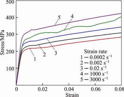
Fig. 1 Stress–strain curves at different strain rates
3.2 Predict results of original Johnson–Cook model
For origin Johnson–Cook model, the flow stress at room temperature (reference temperature) is expressed as
 (1)
(1)
where σ is the von Mises equivalent stress; A is the yield stress at a reference temperature and a reference strain rate; B is the coefficient of strain hardening; C is the coefficient of strain rate hardening; n is the strain hardening exponent; ε is the equivalent plastic strain,  is the dimensionless strain rate.
  is the strain rate. Here
  is the reference strain rate, equals 0.0002 s–1. The material constants in the constitutive expression can be acquired step by step as follows:
1) When strain rate is 0.0002 s–1, which is the reference strain rate; Eq. (1) will be reduced to
σ=A+Bεn (2)
The value of A is acquired easily from the quasi-static yield stress at the reference strain rate.
2) Take logarithm operation on both sides of the equation, then Eq. (2) will change to
ln(σ–A)=lnB+nlnε (3)
Substituting the value of A and flow stress data at various strains into Eq. (3), ln(σ–A) vs lnε is plotted, as shown in Fig. 2. The value of B can be calculated from the intercept of the fitting line, while n is the slope.
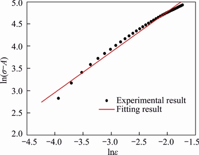
Fig. 2 Relationship between ln(σ–A) and lnε at reference strain rate
Transform Eq. (1) as
 (4)
(4)
Then, substituting the flow stress data for series of strain values corresponding to four strain rates, the relationship between  and
and  at strain rates 0.002, 0.02, 1000 and 3000 s–1 are evaluated. Then series of C values can be obtained from the ratio between and . The values of C, the slopes of the curves, considered to be a constant in the original JC model, but diverse for 7N01 aluminum, are shown in Fig. 3.
Therefore, the value of C in the original JC model is taken as the average of different values of C in Fig. 3. The material constants of the original JC model for 7N01 aluminum alloy are given in Table 2. Using the parameters in Table 2, the predicted stress data at different strain rates using the original JC model are shown in Fig. 4. Compared to experiments results, obvious deviations can be observed, especially for high strain rates (1000 s–1 and 3000 s–1). The prediction accuracy of the original JC model cannot adequately describe flow behaviors of the studied alloy at different strain rate, which may result from neglecting the effect of strain rate on strain rate hardening coefficients.
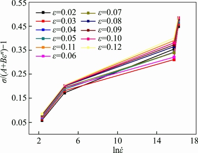
Fig. 3 Relationship between (σ/(A+Bεn)–1) and 
Table 2 Parameters of original JC model for Al 7N01
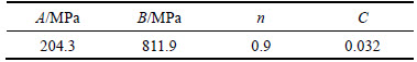
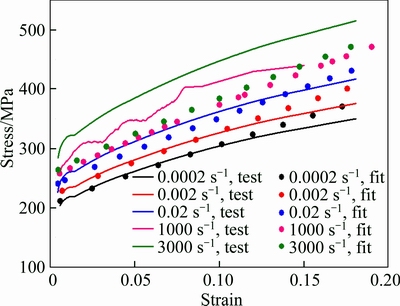
Fig. 4 Stress–strain curves by original JC model predictions
3.3 Modification of original Johnson–Cook model
As discussed in Section 3.2, the value of C is not a constant. Thus, a modified JC model considering the changes of strain rate hardening coefficients at different rates is proposed.
The relationship between factor C and strain ε can be obtained in Fig. 5. It can be observed that C increases slightly with strain rates. The relationship between factor C and strain rate is shown in Fig. 6. The values of C fluctuated with strain rate. It should also be mentioned that the change trend of C at different strains is the same for different strain rates. It means that C can be expressed as a function of strain rates and the function is suitable for different strain rates. Therefore, a model taking the independent variables interaction into account is appropriate to describe the relationships between C and the equation can be written as follows:
 (5)
(5)
where C0, C1, C2, C3 are coefficients needed to be solved. Substituting the values of C at the different strain rates and different plastic strains into Eq. (5), the coefficients C0, C1, C2, C3 can be determined directly.
The material constants of the modified JC model for 7N01 aluminum alloy are given in Table 3.
The flow stress data for the studied alloy under different strain rates are predicted using the modified JC model. Comparisons between the experiment results and predicted results are shown in Fig. 7. It is evident that an improved prediction accuracy is obtained with the modified JC model, especially in the dynamic conditions.
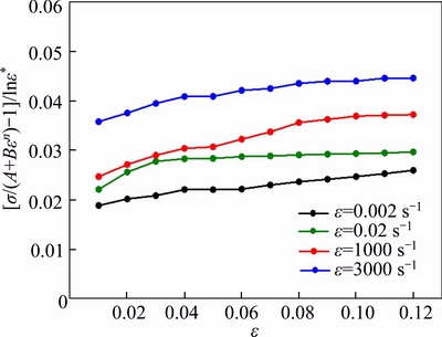
Fig. 5 Relationship between  and ε
and ε
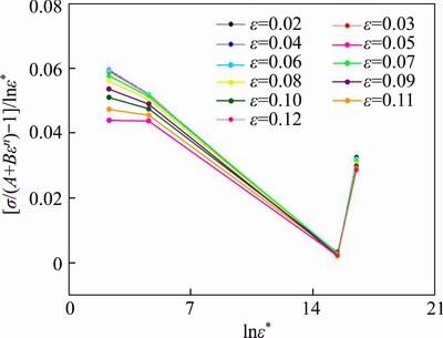
Fig. 6 Relationship between  and
and 
Table 3 Parameters of modified JC model for Al 7N01
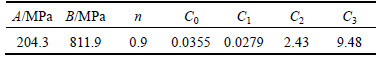
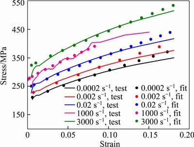
Fig. 7 Stress–strain curves by modified JC model
3.4 Evaluation of modified JC model
The commercial FE code ABAQUS was used to perform simulations of the dynamic test at a strain rate of 1000 s–1. The simulations were performed using the modified Johnson–Cook model, as presented in Section 3.2. The corresponding model parameters are derived by modified JC model shown in Table 3. C3D8R element was used. The FEA model had 25600 elements with an element size of 0.2 mm×0.2 mm×0.4 mm in the gauge section, as depicted in Fig. 8. A predefined velocity field was applied at the right surface of the incident bar. The contact between the specimen and the bars was modeled using surface-to-surface contact. A velocity boundary condition was applied at the right surface of the incident bar. The employed velocity in the simulations was obtained and smoothed using the experimental incident wave measurement. The values of simulated and experimental strain in the incident and transmitted bars are compared in Fig. 9. The numerical reflected and transmitted waves are in good agreement with experimental measurements, as seen in Fig. 9.
In order to acquire the quantitative measurements of the specimen strain distribution from high speed photography, the digital image correlation (DIC) technique described in Section 2.4 was employed. The evolution of the stress–strain curve corresponding to the stages of high speed images is shown in Fig. 10.
The measurement process begins with the measurement of the displacement field by tracking the position of the contrast change (pixel number) while updating the image. Subsequently, the strains were derived at the center of the specimen gauge section by space differentiation of the obtained displacement field data. Although the DIC is called a local measurement technique, the strain in a single point could not be obtained. The strain is actually calculated from the average values displacement of several neighbouring subsets of pixels, typically containing 13 pixels.
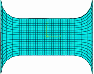
Fig. 8 Mesh in gauge region of FEA model
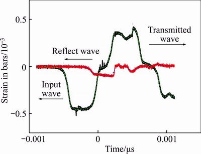
Fig. 9 Comparison of FE analysis output (dashed lines) with experimental results (solid lines) of strain in bar
Figure 12 displays the comparison of experimental results, simulation results and the DIC results. The strains of DIC results are larger than that of simulation and experimental results. This is due to the fact that DIC captures the local behavior whereas the SHPB measurements merely display the overall response. The good agreements of experimental results, simulation results and the DIC results validate the applicability of modified Johnson–Cook constitute model.
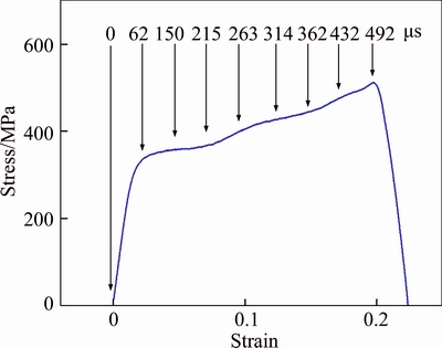
Fig. 10 Evolution of stress–strain curve at time points of high-speed images
4 Conclusions
1) Tensile tests at different strain rates ranging from 0.0002 s–1 to 3000 s–1 show that 7N01 aluminum alloy is strain rate sensitive.
2) A modified Johnson–Cook constitutive equation is proposed, whose coefficient of strain rate hardening parameter C is modified to a function related to strain rate. The fitting results of modified model matched the experimental results better compared to the original Johnson–Cook model.
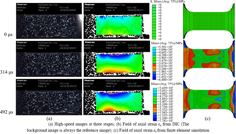
Fig. 11 Comparison for dynamic test at 1000 s–1:
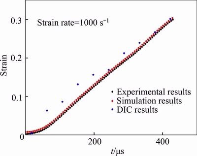
Fig. 12 True strain versus time curve of experimental results, simulation results and DIC results
3) Based on the modified Johnson–Cook model, finite element analysis results show excellent agreement with experiments results and digital image correlation results. High accuracy of the modified Johnson–Cook model is validated.
References
[1] BUSSADORI B P, SCHUFFENHAUER K, SCATTINA A. Modelling of CFRP crushing structures in explicit crash analysis [J]. Composites Part B: Engineering, 2014, 60(1): 725–735.
[2] LI M T, ZHANG Y, KONG C Y. Numerical simulation of bulging process of aluminum alloy sheet [J]. Applied Mechanics & Materials, 2013, 327: 112–116.
[3] FARUKH F, DEMIRCI E, SABUNCUOGLU B, ACAR M, POURDEYHIMI B, SILBERSCHMIDT V V. Mechanical analysis of bi-component-fibre nonwovens: Finite-element strategy [J]. Composites Part B: Engineering, 2015, 68: 327–335.
[4] GAO C Y, ZHANG L C. Constitutive modelling of plasticity of FCC metals under extremely high strain rates [J]. International Journal of Plasticity, 2012, 32–33: 121–133.
[5] FOLLANSBEE P S, KOCKS U F. A constitutive description of the deformation of copper based on the use of the mechanical threshold stress as an internal state variable [J]. Acta Metallurgica, 1988, 36(1): 81–93.
[6] GRAY G T, CHEN S R, VECCHIO K S. Influence of grain size on the constitutive response and substructure evolution of MONEL 400 [J]. Metallurgical & Materials Transactions A, 1999, 30(5): 1235–1247.
[7] ZERILLI F J, ARMSTRONG R W. Dislocation-mechanics-based constitutive relations for material dynamics calculations [J]. Journal of Applied Physics, 1987, 61(5): 1816–1825.
[8] CHIOU S T, CHENG W C, LEE W S. Strain rate effects on the mechanical properties of a Fe–Mn–Al alloy under dynamic impact deformations [J]. Materials Science & Engineering A, 2005, 392: 156–162.
[9] XIE Su-chao, ZHOU Hui. Impact characteristics of a composite energy absorbing bearing structure for railway vehicles [J]. Composites Part B: Engineering, 2014, 67: 455–463.
[10] WAN Yu-min, ZHANG Fa, GU Bo-hong, SUN Bao-zhong, WANG You-jiang. Predicting dynamic in-plane compressive properties of multi-axial multi-layer warp-knitted composites with a meso-model [J]. Composites Part B: Engineering, 2015, 77: 278–290.
[11] PERONI L, SCAPIN M, FICHERA C, LEHMHUS D, WEISE J, BAUMEISTER J, AVALLE M. Investigation of the mechanical behaviour of AISI 316L stainless steel syntactic foams at different strain-rates [J]. Composites Part B: Engineering, 2014, 66: 430–442.
[12] ALEKSANDR C, IGOR T, CHERNIAEV A, TELICHEV I. Meso-scale modeling of hypervelocity impact damage in composite laminates [J]. Composites Part B: Engineering, 2015, 74: 95–103.
[13] PERONI L, SCAPIN M, FICHERA C, LEHMHUS D, WEISE J, BAUMEISTER J, AVALLE M. Investigation of the mechanical behaviour of AISI 316L stainless steel syntactic foams at different strain-rates [J]. Composites Part B: Engineering, 2014, 66: 430–442.
[14] VO T P, GUAN Z W, CANTWELL W J, SCHLEYER G K. Modelling of the low-impulse blast behaviour of fibre–metal laminates based on different aluminium alloys [J]. Composites Part B: Engineering, 2013, 44: 141–151.
[15] MAHESHWARI A K, PATHAK K K, RAMAKRISHNAN N, NARAYAN S P. Modified Johnson–Cook material flow model for hot deformation processing [J]. Journal of Materials Science, 2010, 45(4): 859–864.
[16] CAI J, WANG K, ZHAI P, LI F, YANG J. A modified johnson-cook constitutive equation to predict hot deformation behavior of Ti-6Al-4V alloy [J]. Journal of Materials Engineering & Performance, 2015, 24(1): 32–44.
[17] WANG Y P, HAN C J, WANG C, LI S K. A modified Johnson–Cook model for 30Cr2Ni4MoV rotor steel over a wide range of temperature and strain rate [J]. Journal of Materials Science, 2011, 46(9): 2922–2927.
[18] LIN Y C, CHEN X M. A combined Johnson–Cook and Zerilli–Armstrong model for hot compressed typical high-strength alloy steel [J]. Computational Materials Science, 2010, 49(3): 628–633.
[19] WOSU S N, HUI D, DANIEL L. Hygrothermal effects on the dynamic compressive properties of graphite/epoxy composite material [J]. Composites Part B: Engineering, 2012, 43(3): 841–855.
[20] WOSU S N, HUI D, DUTTA P K. Dynamic mixed-mode I/II delamination fracture and energy release rate of unidirectional graphite/epoxy composites [J]. Engineering Fracture Mechanics, 2005, 72(10): 1531–1558.
[21] NWOSU S N, HUI D, DUTTA P K. Dynamic mode II delamination fracture of unidirectional graphite/epoxy composites [J]. Composites Part B: Engineering, 2003, 34(3): 303–316.
[22] KOLSKY H. An investigation of the mechanical properties of materials at very high rates of loading [J]. Proceedings of the Physical Society: Section B, 1949, 62(11): 676–700.
[23] QIN J G, CHEN R, WEN X J, LI Y L, LIANG M Z, LU F Y. Mechanical behaviour of dual-phase high-strength steel under high strain rate tensile loading [J]. Materials Science & Engineering A, 2013, 586: 62–70.
[24] AMBRIZ R R, FROUSTEY C, MESMACQUE G. Determination of the tensile behavior at middle strain rate of AA6061-T6 aluminum alloy welds [J]. International Journal of Impact Engineering, 2013, 60(10): 107–119.
[25] WANG P F, XU S L, LI Z B, YANG J L, ZHANG C, ZHENG H. Experimental investigation on the strain-rate effect and inertia effect of closed-cell aluminum foam subjected to dynamic loading [J]. Materials Science & Engineering A, 2015, 620: 253–261.
(Edited by HE Yun-bin)
Cite this article as: ZHANG Yi-ben, YAO Song, HONG Xiang, WANG Zhong-gang. A modified Johnson–Cook model for 7N01 aluminum alloy under dynamic condition [J]. Journal of Central South University, 2017, 24(11): 2550–2555. DOI:https://doi.org/10.1007/s11771-017-3668-5.
Foundation item: Projects(51275532, U1334208) supported by the National Natural Science Foundation of China; Project(2015BAG13B01) supported by National Science and Technology Support Program, China; Project(2016YFB1200602-33) supported by the National Key R&D Program of China; Project(NCET-12-0549) supported by the New Century Excellent Talents in University, China; Project(CSUZC201527) supported by the Open-Fund for the Valuable and Precision Instruments of Central South University, China
Received date: 2015-08-28; Accepted date: 2017-09-10
Corresponding author: YAO Song, Associate Professor, PhD; Tel: +86–15116492020; E-mail: song_yao@csu.edu.cn

