Assessment of internal defects of hardfacing coatings in regeneration of machine parts
��Դ�ڿ������ϴ�ѧѧ��(Ӣ�İ�)2018���5��
�������ߣ�Jerzy JOZWIK Krzysztof DZIEDZIC Ireneusz USYDUS Dawid OSTROWSKI Grzegorz M KROLCZYK
����ҳ�룺1144 - 1153
Key words��hardfacing; coating; tomography; welding; defects
Abstract: This paper presents the use of computed tomography for the evaluation of hardfacing. The method used in this research is hardfacing by tungsten inert gas using alloy wires of wear resistant layers. This paper discusses the latest materials used for hardfacing and their application. It characterizes the defects of obtained hardfacing and impact of the type of wire on the concentration of defects. It further, the basic mechanical properties of coatings were determined. The results are subjected to qualitative and quantitative analysis. The smallest average percentage of defects in relation to the overall surface is observed for the hardfacing EL-600 HB, which amounts to 1.5%. The highest average percentage of defects in relation to the overall surface is observed for the hardfacing EL-500 HB, which amounts to 7.2%. The chemical composition of hardfacing has been presented.
Cite this article as: Jerzy JOZWIK, Krzysztof DZIEDZIC, Ireneusz USYDUS, Dawid OSTROWSKI, Grzegorz M KROLCZYK. Assessment of internal defects of hardfacing coatings in regeneration of machine parts [J]. Journal of Central South University, 2018, 25(5): 1144�C1153. DOI: https://doi.org/10.1007/s11771-018-3813-9.

J. Cent. South Univ. (2018) 25: 1144-1153
DOI: https://doi.org/10.1007/s11771-018-3813-9

Jerzy JOZWIK1, Krzysztof DZIEDZIC2, Ireneusz USYDUS3,Dawid OSTROWSKI3, Grzegorz M KROLCZYK4
1. Faculty of Mechanical Engineering, Lublin University of Technology, Lublin 20-816, Poland;
2. Electrical Engineering and Computer Science Faculty, Lublin University of Technology,Lublin 20-816, Poland;
3. Institute of Technical Sciences and Aviation, State School of Higher Education, Chelm 22-100, Poland;
4. Faculty of Mechanical Engineering, Opole University of Technology, Opole 45-758, Poland
 Central South University Press and Springer-Verlag GmbH Germany, part of Springer Nature 2018
Abstract: This paper presents the use of computed tomography for the evaluation of hardfacing. The method used in this research is hardfacing by tungsten inert gas using alloy wires of wear resistant layers. This paper discusses the latest materials used for hardfacing and their application. It characterizes the defects of obtained hardfacing and impact of the type of wire on the concentration of defects. It further, the basic mechanical properties of coatings were determined. The results are subjected to qualitative and quantitative analysis. The smallest average percentage of defects in relation to the overall surface is observed for the hardfacing EL-600 HB, which amounts to 1.5%.The highest average percentage of defects in relation to the overall surface is observed for the hardfacing EL-500 HB, which amounts to 7.2%. The chemical composition of hardfacing has been presented.
Key words: hardfacing; coating; tomography; welding; defects
Cite this article as: Jerzy JOZWIK, Krzysztof DZIEDZIC, Ireneusz USYDUS, Dawid OSTROWSKI, Grzegorz M KROLCZYK. Assessment of internal defects of hardfacing coatings in regeneration of machine parts [J]. Journal of Central South University, 2018, 25(5): 1144�C1153. DOI: https://doi.org/10.1007/s11771-018-3813-9.
1 Introduction
The main cause of machine parts failure causing large expenses for the company is the wear of working surfaces. Currently, one of the most frequently used methods of regenerating machine parts is hardfacing, or applying a layer of liquid metal on the regenerated object. Hardfacing regenerates approximately 65% of machine parts. Surface texture valuation and analysis of defects are important in diagnostics which includes technical assessment of the machines parts by investigating the mechanical properties of its work processes [1�C3]. The purpose of regeneration through the use of hardfacing is to restore the original performance of machine parts [4]. The effective protection of machine parts using hardfacing techniques depends on the impact of the substrate on the deposited alloy, typically assessed by dilution [5]. The beneficial technical and economic effects of regeneration and surface modification through the use of hardfacing, particularly where a maximum resistance to wear and corrosion is required, caused the rapid development of technology and materials for hardfacing. CHAKRABORTY et al [6] presents that in the hardfacing process of modified 9Cr�C1Mo steel, hard layer is unable to absorb thermal stresses resulting in the cracking of the deposit. The currently used hardfacing techniques allow to carry out repairs on virtually any damaged or worn part. Hardfacing materials are classified in DIN 8555. The modern and frequently used materials for hardfacing are electrodes or solid and flux cored wires. The currently used materials are obtained on the basis of Fe, Ni, Co, Ti with additions of various chemical elements, including Si, Cr, B, Mn, V, Mo, W, Nb affecting their mechanical, tribological and corrosive properties [7]. Scientists conduct continuous researches in order to develop such chemical composition of materials for hardfacing, which will ensure the best mechanical, tribological and corrosive properties taking into account the economic aspect. Nitrides and carbides, as well as borides, silicides and oxides are hard materials for the wear-resistant coating. It is thus advantageous to obtain a relatively soft matrix, e.g. Cr7C3, TiC, Fe2B [7, 8]. This increases the resistance to abrasion or corrosion. Therefore, hardfacing frequently uses a material with better properties than the properties of the hardfacing part. From the economic point of view, it is preferred to use the materials based on Fe. The used iron based alloys for the preparation of hardfacing are, inter alia: Fe�CC�CCr, Fe�CC�CCr�CB, Fe�CC�CCr�CTi, Fe�CC�CCr�CTi�CB, Fe�CC�CCr�CMn�CTi, Fe�CC�CMn�CTi, Fe�CC�CCr�CW�CV, Fe�CC�CCr�CNi, Fe�C Mn�CC�CB, Fe�CCr�CC�CNb [9�C11].
In the process of hardfacing, the weld metal is applied to the surface of the parent material while the substrate material is slightly melting. The functional properties and usefulness of hardfacing coatings are greatly affected by their quality or the presence of internal defects or welding imperfections. The quality control of hardfacing is one of the areas where non-destructive testing is applied. To detect defects and inconsistencies in the industrial practice, one uses the same methods as in the testing of welded joints. Among the many methods of non-destructive testing of welded joints and hardfacing coatings, the fundamental role is played by radiographic and ultrasound methods [12�C14]. The modern computer tomography, because of its advantages, is increasingly available and used in industry, including welding. Computed Tomography is a type of X-ray spectroscopy. It is used as a diagnostic method that allows to obtain layered images of examined hardfacing [15]. It uses projection of the object, taken from different directions, to create cross-sectional (2D) and spatial images (3D) [16, 17]. Therefore, computed tomography has been used in the welding industry for non-destructive testing of welded joints and hardfacing coatings.
The aim of the study is to determine the quality and quantity of welding defects, their location and size. Computed tomography is a more accurate method than the currently used X-ray methods. Certain limitations include the high cost of equipment, mobility and size of the measurement area. The study attempts to identify internal defects of wear resistant coatings obtained from modern materials for hardfacing using computed tomography.
2 Materials and methods
The study objects were regenerative hardfacing coatings, obtained by the method of tungsten inert gas. It is a method of (pad) welding with use of a non-fusible electrode in neutral gases. The modern solid welding wires were used to obtain the coatings with the use of hardfacing, characterized by high mechanical properties designated as: EL-500 HB, EL-600 HB, EL-650 HB, EL-2343, EL-3348. These materials are used to regenerate or modify the working surfaces of machine parts and tools, which are required to possess good mechanical properties and high wear resistance. Physicochemical parameters of wires for hardfacing are included in Table 1.
The properties of hardfacing coatings depend not only on the composition of the weld metal, but also from hardfacing technology that can significantly alter the structure of the hardfacing material, which in turn would affect its properties. The process of hardfacing was conducted on a technological station presented in Figure 1(a). The station is composed of the inverter machine TIG AC/DC ControlPro LORCH. Technological parameters applied in the process of hardfacing for all wires are presented in Table 1, the current intensity 80 A, voltage 18 V, positive polarity. The employed protective gas was argon with purity of 99.9%.
The process of hardfacing was carried out on the front surface of the steel shaft C45 with a diameter of 60 mm and a height of 50 mm. The chemical composition of the steel C 45 is shown in Table 2. Four layers of each hardfacing were applied, according to the literature allowed to obtain a composition close to that of the used wires.
Table 1 Physicochemical parameters of wires for hardfacing

Table 2 Chemical composition of steel C45 (mass fraction, %)

After obtaining the hardfacing, lathe machining was carried out on the entire front surface in order to give certain geometrical characteristics to the studied sample (d50 mm, l=20 mm), as shown in Figure 1(b). Lathe machining was carried out on both the front surface and the cylindrical surface.The samples were then cut off from the rest of the shaft while keeping the height of the sample h=5 mm, taking into account the machining allowance at the 0.3 mm level(Figure 1(b)). The grinding process was carried out on a grinding machine to the planes of Kent company. After grinding process, samples were given final geometric parameters d50 mm��5 mm.
The assessment of discontinuity of the internal structure and internal defects was made using the computed tomography (CT) scanner X25 (North Star Imaging) presented in Figure 1(c), X-ray source: Hamamatsu L12161-07, voltage: 150 kV, current: 500 ��A, focal spot size: 30 ��m, focal spot mode: medium. Detector name: Varian, pixel pitch: 127 ��m��127 ��m, framerate: 10 fps (100 ms integration time), flip: none, rotation: 90��, crop: (l, t, r, b)=(10,10,10,10) pixels. Figure 1(d) shows an X-ray image from the front of the hardfacing. The study consisted of directing a beam of radiation to the test object and recording its intensity on the other side, on the panel of detectors. While passing through the studied object, the radiation experiences weak points, which is a function of radiation energy, the type and thickness of the studied material and the presence of defects, pores, cracks and discontinuities. As a result of the projection made of different directions, cross-sectional images (2D) and spatial images (3D) were created. Modeling of the object allowed a detailed analysis and location of internal defects of the obtained hardfacing.

Figure 1 Schematic diagram of experimental arrangement
In order to assess the hardness of the hardfacing, measurements were taken by micro hardness tester KB-10 of Prauftechnik for Vickers Hardness HV10 and micro hardness tester 600MRD of Wolpert for HRC method. To compare measurements obtained from both methods and hardnesses declared by the manufacturer, the results from the HV10 measurement were converted to HRC.
The mobile analyzer of metals SPECTROTEST TXC25 with paark analyzer vision ME software was used to study the chemical composition, allowing to identify the species of low-alloy steel with carbon and aluminum content. SPECTROTEST is also equipped with a calibration for the analysis and for the following bases: Al, Fe, Cu, Ni, Co, Pb, Sn, Zn, Ti, Mg. The results are shown in Table 3.
It detects 21 elements contained in the material and compares it with a database of chemical composition of metals stored in the machine (SPECTRO Metal Database). It has an intelligent logic calibration ICAL that allows to calibrate the entire spectrometer with only one sample (recalibration pattern ICAL). It is equipped with an optical system based on a high resolution detectors CCD, digitally controlled generator of sparks, exchangeable UV measuring head for elements, e.g. C, P, S, high-performance reading system PC with Windows XP Professional. The results of analysis performed in argon atmosphere 5.0 for each element are presented as the average of 3 samples from a random positions on the sample surface. The main components were distinguished. The imposition of four layers for each of the hardfacing made it possible to obtain the chemical composition of the surface similar to the one declared by the manufacturer. All basic elements were identified, but their concentration in most hardfacing in lower than that declared by the manufacturer.
Table 3 Chemical composition of welding coatings (mass fraction, %)

3 Results and discussion
On the basis of conducted experimental studies of regenerative hardfacing, a quantitative and qualitative assessment of internal defects of pad weld was made.Hardness testing and testing of the chemical composition were conducted on the front surface of the sample. All hardfacing were found to contain internal defects in the form of pores and craters. The porosity of hardfacing is due to the formation of bubbles in the metal at the time of its freezing. There were no cracks or detachment of the hardfacing from the substrate.
The next step involved the assessment of internal defects of hardfacing EL-500 HB, EL-600 HB, EL-650 HB, EL-2343, EL-3348 as shown in Figure 2(a)�C(d). Several smaller pores can be observed in the hardfacing 500 EL-HB, as shown in Figure 2(a). Large pores are present in the hardfacing EL-650 HB and EL-2343, as shown in Figures 2(c) and (d).
Then, the distribution and concentration of internal defects in the hardfacing were tested in successive layers located in the front surface in the following distances: ~0, 1, 2, 3, 4, ~5 mm. The distribution and concentration of internal defects in the hardfacing EL-500 HB in successive layers located in the front surface are presented in Figure 3. The hardfacing EL-500 HB contains a large number of internal defects in the form of pores and craters. Their number is reduced at the surface and in the layer from the side of the parent material.
The subsequent step involved a procedure of determining the concentration of pores and internal defects of hardfacing using the software environment. Figure 4 shows the methodology of the procedure for determining the calculation of the percentage share of pores in the total surface. Figure 4(a) shows the X-ray image in the specified cross-section. Figure 4(b) shows the processed image as a result of assigning a binary color to individual colors of the surface in the software environment. The last step was to obtain the calculation of the percentage share of pores in the total surface, which is presented in Figure 4(c).

Figure 2 Assessment of defects in hardfacing
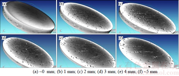
Figure 3 Distribution and concentration of defects in hardfacing EL-500 HB at different distances
The final step was to determine the percentage share of defects in relation to the total surface at various depths from the surface of hardfacing. This enabled the comparison of the quality of obtained hardfacing. The concentration of pores and internal defects in hardfacing is shown in Figure 5. The lowest average percentage share of defects in relation to the total surface was obtained for the hardfacing EL-600 HB, which amounted to 1.5%. The maximum percentage share was registered at a depth of 3 mm, which amounted to 2%. By contrast, the minimum percentage share was registered at a depth of 5 mm, which amounted to 1%.
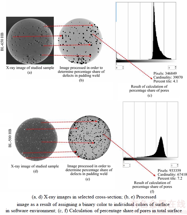
Figure 4 Procedure for determining concentration of pores and internal defects in hardfacing using a software environment for hardfacing EL-500 HB and EL-650 HB
The distribution obtained for the hardfacing EL-600 HB is evenly distributed. The average percentage share of defects in relation to the total surface for the hardfacing EL-2343, amounted to 2.72%. It amounted to 3.43% for the hardfacing EL-3348, and 4.38% for the hardfacing EL-650 HB. The largest average percentage share of defects in relation to the total surface was obtained for the hardfacing EL-500 HB, which amounted to 7.2%. The maximum percentage share was registered at a depth of 4 mm, which amounted to 7.4%. The lowest concentration of defects is present in the vicinity of the core material and the surface of the hardfacing.
Figure 6 presents the distribution of changes in the hardness of obtained hardfacing on the surface of the studied samples. The results are presented on a background of hardness specified by the manufacturer of wires used for hardfacing. It was observed that most hardfacing achieved a slightly higher hardness than that indicated by the manufacturer.

Figure 5 Concentration of pores and internal defects in hardfacing

Figure 6 Change of hardness in surface of hardfacing
The higher hardness value is achieved by hardfacing made from: EL-3348 (an increase by about 33�C8 HRC), EL-500 HB (an increase by about 0.6�C4.5 HRC), EL-600 HB (an increase by about 0�C1.5 HRC). Based on the analysis of results shown in Figure 6, two hardfacing showed a reduced hardness in relation to the one declared by the manufacturer. The hardfacing EL 2343 has a lower hardness of 2�C6 HRC, while the hardfacing EL-650 HB has a lower hardness of 4�C7 HRC. Hardness tests allow to obtain similar values to the ones declared by the manufacturer.
4 Conclusions
The results obtained show that the method used to obtain a hardfacing with tungsten inert gas (TIG) can be proper to the regeneration of machine parts. This has been possible thanks to the suitable design of the experimental methods. Based on the observations from experiments, the authors formulated the following conclusions:
1) The applied computed tomography method in comparison to conventional radiography gives much greater opportunities to diagnose and control the hardfacing layers and welded joints. It increases the ability to detect defects and welding imperfections, which allows an assessment of hardfacing and determination of their operational usefulness. It provides a quantitative and qualitative assessment of internal defects. It allows to determine the concentration of defects in the hardfacing. The study showed that the CT is a prospective method of non-destructive testing, which can be successfully used to control hardfacing coatings.
2) The conducted research for hardfacing obtained with the use of modern solid welding wires for hardfacing EL-500 HB, EL-600 HB, EL-650 HB, EL-2343, EL-3348 of most allowed to assess the qualitative and quantitative participation of internal defects. The most numerous defects were pores and craters. There were no cracks and detachment in hardfacing. The smallest average percentage share of defects in relation to the total surface was obtained for the hardfacing EL-600 HB, which amounted to 1.5%. The highest average percentage share of defects in relation to the total surface was obtained for the hardfacing EL-500 HB, which amounted to 7.2%.
3) It was observed that most hardfacing achieved a slightly higher hardness than the one indicated by the manufacturer.
4) The imposition of four layers of hardfacing allowed to obtain chemical composition similar to that declared by the manufacturer in all hardfacing. The comparative analysis demonstrates that among all analyzed samples the best properties were achieved by a coating obtained from the wire EL-600 HB. This coating has the highest amount of alloying elements chromium and silicon in its composition. The coating EL-500HB has the smallest amount of alloying elements in its composition and is characterized by the highest percentage share of defects in the hardfacing.
References
[1] LEHOCKA D, KLICH J, FOLDYNA J, HLOCH S, KROLCZYK J B, CARACH J, KROLCZYK G M. Copper alloys disintegration using pulsating water jet [J]. Measurement, 2016, 82: 375 �C383. DOI: 10.1016/ j.measurement.2016.01.014.
[2] GLOWACZ A, GLOWACZ A, KOROHODA P. Recognition of monochrome thermal images of synchronous motor with the application of binarization and nearest mean classifier [J]. Archives of Metallurgy and Materials, 2014, 59(1): 31�C34. DOI: 10.2478/ amm-2014-0005.
[3] WOJCIECHOWSKI S, MARUDA R W, KROLCZYK G M, NIESLONY P. Application of signal to noise ratio and grey relational analysis to minimize forces and vibrations during precise ball end milling [J]. Precision Engineering, 2016, 51: 582�C596. DOI: 10.1016/ j.precisioneng.2017.10.014.
[4] YANG K, YANG K, BAO Y F, JIANG Y F. Formation mechanism of titanium and niobium carbides in hardfacing alloy [J]. Rare Metals, 2017: 36(8): 640�C644. DOI: 10.1007/ s12598-016-0777-5.
[5] DA SILVA L J, D'OLIVEIRA A. NiCrSiBC coatings: Effect of dilution on microstructure and high temperature tribological behaviour [J]. Wear, 2016, 350: 130�C140. DOI: 10.1016/j.wear.2016.01.015.
[6] CHAKRABORTY G, DAS C R, ALBERT S K, BHADURI A K, MURUGESAN S, DASGUPTA A. Effect of alloy 625 buffer layer on Hardfacing of modified 9Cr-1Mo steel using nickel base Hardfacing alloy [J]. Journal of Materials Engineering and Performance, 2016, 25(4): 1663�C1672. DOI: 10.1007/ s11665-016-1965-z.
[7] WANG X H, ZOU Z D, QU S Y. Microstructure of Fe-based alloy hardfacing coating reinforced by TiC-VC particle [J]. Journal of Iron and Steel Research, 2006, 13(4): 51�C55. DOI: 10.1016/S1006-706X(06) 60078-2.
[8] PASHECHKO M, DZIEDZIC K, BARSZCZ M. Study of the structure and properties of wear-resistant eutectic Fe-Mn-C-B-Si-Ni-Cr coatings [J]. Powder Metallurgy and Metal Ceramics, 2013, 7�C8(52): 469�C476. DOI: 10.1007/ s11106-013-9549-z.
[9] YUKSEL N, SAHIN S. Wear behavior�Chardness�C microstructure relation of Fe�CCr�CC and Fe�CCr�CC�CB based hardfacing alloys [J]. Materials and Design, 2016, 58: 491�C498. DOI: 10.1016/j.matdes. 2014. 02.032.
[10] CORREA E O, ALCANTARA N G, VALERIANO L C, BARBEDO N D, CHAVES R R. The effect of microstructure on abrasive wear of a Fe�CCr�CC�CNb hardfacing alloy deposited by the open arc welding process [J]. Surface & Coatings Technology, 2015, 276: 479�C484. DOI: 10.1016/j.surf coat.2015. 06.026.
[11] BADISCH E, KATSICH C, WINKELMANN H, FRANEK F, MANISH R. Wear behavior of hardfaced Fe-Cr-C alloy and austenitic steel under 2-body and 3-body conditions at elevated temperature [J]. Tribology International, 2010, 43: 1234�C1244. DOI: 10.1016/ j.trib oint.2010.01.008.
[12] VALAVANIS I, KOSMOPOULOS D. Multiclass defect detection and classification in weld radiographic images using geometric and texture features [J]. Expert Systems with Applications, 2010, 37: 7606�C7614. DOI: 10.1016/ j.eswa.2010.04.082.
[13] ZAPATA J, VILAR R, RUIZ R. Performance evaluation of an automatic inspection system of weld defects in radiographic images based on neuro-classifiers [J]. Expert Systems with Applications, 2011, 38: 8812�C8824. DOI: 10.1016/j.eswa.2011.01.092.
[14] TABATABAEIPOUR M, HETTLER J, DELRUE S, ABEELE K. Non-destructive ultrasonic examination of root defects in friction stir welded butt-joints [J]. NDT&E International, 2016, 80: 23�C34. DOI: 10.1016 /j.ndteint. 2016.02.007.
[15] KROLCZYK J B, GAPINSKI B, KROLCZYK G M, SAMARDZIC I, MARUDA R W, SOUCEK K, JAVADI Y, LEGUTKO S, NIESLONY P, STAS L. Topographic inspection as a method of weld joint diagnostic [J]. Tehnicki Vjesnik�CTechnical Gazette, 2016, 23(1): 301�C306. DOI: 10.17559/TV- 20141230182054.
[16] DINDA S K, WARNETT J M, WILLIAMS M A, ROYA G, SRIRANGAM P. 3D imaging and quantification of porosity in electron beam welded dissimilar steel to Fe-Al alloy joints by X-ray tomography [J]. Materials and Design, 2016, 96: 224�C231. DOI: 10.1016/j.matdes. 2016.02.010.
[17] YANG M, XIONG S M, GUO Z. Characterization of the 3-D dendrite morphology of magnesium alloys using synchrotron X-ray tomography and 3-D phase-field modelling [J]. Acta Materialia, 2015, 92: 8�C17. DOI: 10.1016/j.actamat.2015.03.044.
(Edited by HE Yun-bin)
���ĵ���
������жѺ�Ϳ���ڲ�ȱ�ݵ�����
ժҪ�����IJ��ü�����ϲ�ɨ�輼���ԶѺ�Ч�����������������ټ��������屣�����жѺ�������Ϊ��ĥͿ��ĺϽ��ߡ����������µĶѺ����ϼ���Ӧ�á��ԶѺ�Ϳ���ȱ�ݽ��б��������о������߲Ķ�ȱ��Ũ�ȵ�Ӱ�졣���⣬������Ϳ��Ļ�����ѧ���ܣ��Բ��Խ�����ж��ԺͶ������������������EL-600 HB�Ѻ�Ϳ���ܱ����ƽ��ȱ�ݰٷ�����С��Ϊ1.5%��EL-600 HB�Ѻ�Ϳ���ܱ����ƽ��ȱ�ݰٷ������Ϊ7.2%������˶Ѻ�Ϳ��Ļ�ѧ�ɷ֡�
�ؼ��ʣ��Ѻ���Ϳ�㣻�ϲ�ɨ���������ӣ�ȱ��
Received date: 2016-06-02; Accepted date: 2017-10-24
Corresponding author: Grzegorz M KROLCZYK, PhD, Professor; Tel: +48�C77449�C8429; E-mail: g.krolczyk@po.opole.pl; ORCID: 0000-0002-2967-1719

