
New inverse method for identification of constitutive parameters
ZHOU Ji-ming(周计明), QI Le-hua(齐乐华), CHEN Guo-ding(陈国定)
School of Mechatronic Engineering, Northwestern Polytechnical University, Xi’an 710072, China
Received 8 May 2005; accepted 16 August 2005
Abstract: A new inverse method by coupling iSIGHT and ABAQUS was proposed to determine the constitutive parameters of Al2O3sf/LY12 composite deforming at elevated temperature. It combined the merits of the finite element simulation and optimization technique. The direct model was simulated with finite element code ABAQUS. The inverse problem associated with the identification of the constitutive parameters was expressed as a least square optimization problem. The direct simulation and the parameters optimization were implemented in iSIGHT integrated environment. The aim was to match the output of the direct simulation with the experiment data. The capability of the proposed inverse method was demonstrated through the identification of constitutive parameters of Al2O3sf/LY12 composite. The proposed new inverse method is also applicable to other parameters identification which is hardly determined through experiments or direct analytical method.
Key words: Al2O3sf/LY12 composite; constitutive parameters; inverse method; parameter identification; hot deformation; iSIGHT; ABAQUS
1 Introduction
The finite element analysis(FEA) of the forming process may reduce the cost and enhance the properties of the products. The precision of the FEA is based on the material model and the model parameters[1, 2]. Given a material model, the attention is focused on the parameters identification. The parameters are identified through different mechanical tests, such as tension, torsion and compression. Very often though, the measurement (as for the load and displacement) during the mechanical tests can not be used directly but have to be converted into some values (as for stress and strain) involved in the constitutive equations[3]. This conversion introduces errors in the identified parameters for the case of some approximation as in large deformations for instance. In addition, the standard identification methods require the special experiment configuration to reduce the friction, ensure constant strain rate and temperature etc. But real forming process cannot ensure these serious conditions[4]. So the simulation results can not reflect the real situation[5].
Inverse method can identify the constitutive parameters more accurately as it is based on the straight comparison of the measured and calculated responses of the material[6]. The calculated responses can be obtained from finite element simulations. Inverse identification uses optimization techniques to adjust constitutive parameters so that the calculated responses match the measured ones in a particular norm. The difficulties lie in the optimization algorithm implementation. We have to calculate the sensitivity of parameters after the finite element analysis and compile the optimization procedure to couple the FEA code. This is a tedious and difficult work and it elongates the research time.
The finite element code ABAQUS was integrated into the optimizer iSIGHT environment to realize the inverse identification of constitutive parameters in this paper. With the initial and boundary condition similar to the mechanical experiments, ABAQUS calculated the response of Al2O3sf/LY12 under some load conditions. The constitutive parameters used by ABAQUS were optimized by iSIGHT in the integrated environment. The aim was to reduce the gap between the calculated loads and measured loads during experiments along the load history. The new inverse method combined the merits of FEA code ABAQUS and the optimizer iSIGHT, and eased the identification of constitutive parameters.
2 Direct model
The modeling approach, which assumes that the constitutive parameters of the material are known, is often used and called the direct method. Generally, with the suitable input variables, the finite element code ABAQUS can provide the thermo-mechanical simulation of forming process or mechanical tests[7]. The input variables include many aspects, such as mechanical behavior of the materials, the contact between the tools and workpiece, the geometry shape of products, initial conditions and boundary conditions. As the tool materials are much harder and stronger than the workpiece, it is modeled as the rigid body usually. The mechanical behavior of the workpiece is modeled with the constitutive equations. Temperature changes due to plastic work and losses to the environment are important during the deformation of workpiece, especially at fast and cold forming process. Material behavior is usually temperature dependent. So the thermo-mechanical couple analysis is required.
As for the verification example given in this paper, the hyperbolic sine constitutive equation was used as the material model. The friction behavior was considered rough during direct simulation. The constant deformation speed boundary condition was selected similar to the mechanical experiments. The load and displacement were calculated by the finite element analysis.
3 Inverse method
Inverse method is important tool for determining parameters appearing in the direct models, where the goal is to determine a set of parameters that minimize the difference between the calculated values of a model using a functional form (e.g. constitutive equation) and the corresponding experimental data (e.g. results of a mechanical test)[8]. The problem was formulated as a least square problem[9]:
Find  , such as
where
 (1)
(1)
where  is the cost function;
  is the ith calculated value;
  is the ith measured value; P is the parameters to be optimized; n is the number of measurements and
  is the constraint space. As for the verification example given in section 4, P is the constitutive parameters to be optimized and D is the reaction force at given displacement.
Eqn.(1) was solved by coupling iSIGHT and ABAQUS in this paper. Fig.1 shows the flow chart of the new inverse method. In this method, three components were included: 1) one or more experiments in which related measurements Dexp were recorded about samples that may be arbitrarily shaped or multi-axially loaded; 2) the numerical simulation (ABAQUS analysis) of the experiments with similar initial and boundary conditions to experiments; 3) optimizer iSIGHT providing very professional optimization algorithms to adjust the parameters based on the output of the direct model analyzed by ABAQUS. Two criteria were used to stop the opti- mization: the max number of the optimization defined by
Cout<Num (2)
and the global convergence of the cost function defined by
 (3)
(3)
where Num and EPS are the max number of optimization and the global convergence error respectively given by the user.
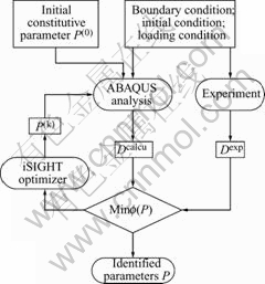
Fig.1 Flow chart of new inverse method by coupling iSIGHT and ABAQUS
4 Application to identification of constitutive parameters of Al2O3sf/LY12
As an application of the above described inverse method, the identification of constitutive parameters of Al2O3sf/LY12 in the hot working regime were presented. The constitutive model used to represent the behavior provides an expression of the flow stress as a function of the equivalent viscoplastic strain, the strain rate and the temperature, following the equation[10-13]:
 (4)
(4)
where R is the gas constant;  is the equivalent plastic strain rate;
  is the equivalent stress, A, n, α and Q are the constitutive parameters to be identified. The constitutive parameters A, n, α and Q in Eqn.(4) are equivalent to the parameter P in Eqn.(1).
The inverse identification of the constitutive parameters was performed using the axisymmetric compression test at high temperatures[14-17]. The samples were loaded at constant deformation speed (mm/min). The loads and displacements recorded during the tests were used to be the measurements. The response of Al2O3sf/LY12 was calculated by ABAQUS with automatic increments. The direct model took into account the friction between the tool and sample during the tests. The friction was regarded as rough and the sample didn’t slide after the contact. In the future research, the friction coefficient will also be obtained by inverse method described above.
As mentioned above, the reaction force (load) at different displacements was used to the value of D in Eqn.(1). The experiment value Dexp was recorded during tests. The calculated value Dcal can be gained from the simulation of FEA. The aim of the inverse identification was to reduce the gap between Dexp and Dcal through adjusting the constitutive parameters used by FEA code ABAQUS. When ABAQUS was integrated into the optimizer iSIGHT, two key problems should be solved. Firstly, we cannot get the serial calculated loads from the output files of ABAQUS directly. So the postprocessing program needs to be compiled to retrieve the loads and displacements from the ABAQUS result files. Secondly, when we compare the calculated loads with the measured loads, we will find they are recorded at different displacements. This is caused by the automatic increment of ABAQUS during analysis. So we have to interpolate the values of experiments at the same displacements as the calculated. This also needs to be implemented in the postprocessing program. After obtaining the calculated loads and corresponding measured loads, the cost function was calculated at last. These two problems were solved in this paper successfully.
Initial constitutive parameters are important for success identification. Analytical method was used to determine the initial constitutive parameters from a large of experiments conducted at different tempera- tures and different deformation speeds. The elastic modulus of the composite was calculated from the compression test. The variation of elastic modulus with the temperature is illustrated in Table 1. Initial parameters and identified parameters are listed in Table 2.
Table 1 Variation of elastic modulus at different temperatures
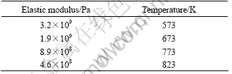
Table 2 Initial and identified constitutive parameters
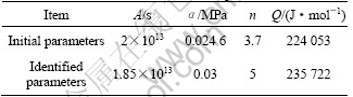
Fig.2 shows the comparison between the calculated and measured loads. From Fig.2 it can be found that the calculated loads differ from the experiments significantly before optimization. After the optimization, the calculated loads coincide with the experiment very well. In this example, although the experiment data at 500 ℃, 1 mm/min deformation speed was used to inverse identification of constitutive parameters, the constitutive parameters identified through inverse method with one set of experiment data are applicable to other deformation conditions. The generality of the constitutive parameters was verified through other simulations under different deforming conditions. The comparison between the simulated and measured is illustrated in Fig.3. Fig.3 shows the constitutive parameters optimized from one experimental condition can be used to simulate the deformation under other experimental conditions. This is one of the main merits of inverse methods. That is we can reduce the cost of experiments. Fig.2 and Fig.3 show that the method proposed in this paper is successful.
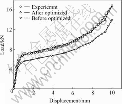
Fig.2 Comparison between calculated loads and measured loads (500 ℃, 1 mm/min)
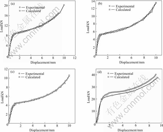
Fig.3 Comparison between calculated loads and measured loads: (a) 500 ℃, 3mm/min; (b) 525 ℃, 1 mm/min; (c) 550 ℃, 1mm/min; (d) 400 ℃, 3 mm/min
5 Conclusions
1) Combination of optimization techniques with finite element method, which takes account of inhomogeneity of strain rate, strain and temperature distribution, is important to fit experimental test data to local deformation conditions.
2) The optimizer iSIGHT and FEM code ABAQUS are coupled to determine the constitutive parameters. This new inverse method combines the merits of the optimizer and FEA software.
3)The constitutive parameters determined by the inverse method reflect the reality more exactly. The validness of this new inverse method is demonstrated with the identification of constitutive parameters of Al2O3sf/LY12 deforming at high temperatures. The identification results show the calculated loads match the measured loads well during deformation.
4) The new inverse method proposed in this paper is also applicable to other parameters identify- cation, such as thermal properties and geometric shape.
References
[1] Lauro F, Bennani B, Croix P, Oudin J. Identification of the damage parameters for anisotropic materials by inverse technique: Application to an aluminium[J]. Journal of Materials Processing Technology, 2001, 118(1-3): 472-477.
[2] Gontarz A. Comparative study of the flow characteristics of AlCu2SiMn alloy[J]. Journal of Materials Processing Technology, 2003, 138(1-3): 156-162.
[3] Ghouati O, Gelin J C. Inverse identification methods for materials parameters estimation in metal forming[A]. Simulation of Materials Processing: Theory, Methods and Applications[C]. Netherlands: Balkema & Rotterdam, 1995. 569-574.
[4] Meuwissen M H H, Oomens C W J, Baaijens F P T, Petterson R, Janssen J D. Determination of the elasto-plastic properties of aluminium using a mixed numerical-experimental method[J]. Journal of Materials Processing Technology, 1998, 75(1-3): 204-211.
[5] Gavrus A, Massoni E, Chenot J L. An inverse analysis using a finite element model for identification of rheological parameters[J]. Journal of Materials Processing Technology, 1996, 60: 447-454.
[6] Lam Y C, Khoddam S, Thomson P F. Inverse computational method for constitutive parameters obtained from torsion, plane-strain and axisymmetric compression tests[J]. Journal of Materials Processing Technology, 1998, 83(1-3): 62-71.
[7] ABAQUS, Inc. ABAQUS User Documentation [Z]. USA, 2004.
[8] Milani A S, Nemes J A. An intelligent inverse method for characterization of textile reinforced thermoplastic composites using a hyperelastic constitutive model[J]. Composites Science and Technology, 2004, 64(10-11): 1565-1576.
[9] Forestier Romain, Massoni E, Chastel Y. Estimation of constitutive parameters using an inverse method coupled to a 3D finite element software[J]. Journal of Materials Processing Technology, 2002, 125-126: 594-601.
[10] Winston A W, Jonh J J. Aluminum extrusion as a thermally activated process[J]. Transactions of the Metallurgical Society of AIME, 1968, 242: 2271-2280.
[11] van de Langkruis J, Bergwerf R, van der Zwaag S, Kool W H. Linking plane strain compression tests on AA6063 to laboratory scale extrusion via constitutive equations[J]. Materials Science Forum, 2000, 331 (I): 565-570.
[12] McQueen H J, Belling J. Constitutive constants for hot working of Al-4.5Mg-0.35Mn (AA5182)[J]. Canadian Metallurgical Quarterly, 2000, 39(4): 483-492.
[13] McQueen H J, Ryan N D. Constitutive analysis in hot working[J]. Materials Science and Engineering A, 2002, 322(1-2): 43-63.
[14] Wang Q G. Plastic deformation behavior of aluminum casting alloys A356/357[J]. Metallurgical and Materials Transactions A: Physical Metallurgy and Materials Science, 2004, 35A(9): 2707-2718.
[15] Zhou H T, Zeng X. Q, Wang Q D, Ding W J. Flow stress model for AZ61 magnesium alloy[J]. Acta Metallurgica Sinica (English Letters), 2004, 17(2): 155-160.
[16] SUN Jia-kuan, LUO Shou-jing. Mechanical behaviors of tension and compression deformation of 2024Al alloy at semi-solid state[J]. The Chinese Journal of Nonferrous Metals, 1999, 9(3): 493-498.(in Chinese).
[17] DU Zhi-ming, LUO Shou-jing, SUN Jia-kuan. Deformation mechanism of tension of 2024Al alloy at semi-solid state[J]. Trans Nonferrous Met Soc China, 2000, 10(5): 666-670.
Foundation item: Project(50575185) supported by the National Natural Science Foundation of China; Project(51412010304HK0339) supported by the Founda- tion of National Defense, China; Project(05G53048) supported by the Foundation of Aeronautical Science, China
Corresponding author: ZHOU Ji-ming; Tel: +86-29-88488017; E-mail: zhoujm@mail.nwpu.edu.cn
(Edited by LI Xiang-qun)

