
J. Cent. South Univ. (2019) 26: 1830-1839
DOI: https://doi.org/10.1007/s11771-019-4137-0

Nested Newmark model to estimate permanent displacement of seismic slopes with tensile strength cut-off
ZHOU Zheng(ЦЬХю), ZHANG Fei(ХЕ·Й), GAO Yu-feng(ёЯУс·е), SHU Shuang(КжЛ¬)
Key Laboratory of Ministry of Education for Geomechanics and Embankment Engineering,Hohai University, Nanjing 210098, China
 Central South University Press and Springer-Verlag GmbH Germany, part of Springer Nature 2019
Abstract: Nested Newmark model(NNM) is a conceptual framework to assessing post-earthquake movements including dispersed shear movements. The original NNM omits that the tensile stresses would be encountered in slopes induced by earthquakes. The purpose of this study is to introduce the tensile strength cut-off and the relevant failure mechanism into NNM and conduct the limit analysis to determine the seismic displacement. Parametric studies are carried out to further investigate the influence of the tensile strength and input ground motions on permanent displacement. Neglecting the tensile strength can underestimate the permanent displacements of slopes. As the peak acceleration increases, the underestimation becomes more significant. With the reduction of tensile strength, much larger deformation occurs next to the slope crest. Although the present results are limited to an example, the method is of value in practice to predict the post-earthquake profile of slope.
Key words: slopes; limit analysis; earthquakes; permanent displacement; Newmark; tensile strength
Cite this article as: ZHOU Zheng, ZHANG Fei, GAO Yu-feng, SHU Shuang. Nested Newmark model to estimate permanent displacement of seismic slopes with tensile strength cut-off [J]. Journal of Central South University, 2019, 26(7): 1830-1839. DOI: https://doi.org/10.1007/s11771-019-4137-0.
1 Introduction
Landslides triggered by earthquakes are prevalent concerns in mountainous regions. The approaches to assess stability of seismic slopes could be divided into three main categories: pseudo-static method [1, 2], Newmark sliding block analysis [3, 4], and stress-deformation analysis [5, 6]. The pseudo-static method conducts the limit equilibrium (LE) or limit analysis (LA) to obtain the factor of safety for a given peak acceleration and neglects the acceleration-time history of the seismicity. The Newmark method can determine the permanent displacement of the slope during the earthquake. Furthermore, using dynamic analyses based on the finite-element (FE) or finite-difference (FD) numerical methods [7, 8] can obtain the stress and strain results of the slopes induced by the earthquakes. But the accuracy of the numerical results depends on the soil dynamic constitutive and boundary conditions. The estimation of permanent displacement of slope based on Newmark method bridges the gap between the simplified pseudo- static method and complicated stress-deformation analysis.
The Newmark method simplifies the failure of slopes or earth dams as the single rigid block sliding and the obtained results are verified with model tests [9, 10]. Through shaking table model tests in the centrifugal field, KUTTER et al [11] find a deep rotational failure surface in a clay embankment. The Newmark method is developed to determine the displacement using a log-spiral surface in LE or LA [12, 13]. However, the rotational failure mechanism is limited to sliding of a rigid body. The experimental results demonstrate general deformations which exhibit multiple failure surfaces or regions of internal shear movements [10, 11]. To obtain the general deformation in Newmark method, LESHCHINSKY [14] recently proposes a nested Newmark model (NNM) to determine the post-earthquake displacement profiles of slopes using both of planar and rotational failure surfaces in LE. The effects of multiple slip surfaces and dispersed regions of internal shear movement are involved in NNM. These Newmark models are limited to the linear Mohr-Coulomb (M-C) yield criterion. The seismicity often induces tensile stresses in the slope crest. To eliminate the negative stresses, a tension crack is considered and non-linear yield criterion is involved [15, 16]. As investigated by UTILI et al [17], the pre-existing crack can significantly increase the permanent displacement of seismic slope and yields an underestimation of the seismic slopes. Recently, MICHALOWSKI [18] introduces a non-linear yield criterion caused by the elimination of the soil tensile strength in the stability analysis of intact slopes. The non-linear yield criterion is adopted here to modify the NNM for calculating the post-earthquake profile of slopes with tensile strength cut-off. Parametric studies are carried out to investigate the influence of the tension cut-off on the seismic displacement.
2 Methodology
2.1 Tensile strength cut-off
The linear MC yield criterion is often used in slope stability analyses. DRUCKER et al [19] introduce the concept of tension cut-off to modify the MC criterion, as illustrated in Figure 1. The MC function can be expressed as a straight line combined with a segment of a circular arc. The triaxial tensile strength equates to f3t=c/tan¦Х, while the uniaxial tensile strength equal to ft=2ccos¦Х/ (1+sin¦Х) in MC criterion. When the tensile strength is considered, the traction vector changes from the straight line to the arc with the variation in dilatancy angle ¦Д from its value ¦Х to ¦Р/2. The change of dilatancy corresponds to the rotation of the strain rate vector, as shown in Figure 1(a). In this case, the tensile strength is zero. To quantify the effects of tensile strength, a reduction fraction ¦О that satisfies 0ЎЬ¦ОЎЬ1 is introduced and the tensile strength could be expressed as
 (1)
(1)
Using the modified criterion, an expression of work dissipation done by tensile strength is derived by MICHALOWSKI [18] in LA as:
 (2)
(2)
where fc is the uniaxial compressive strength in the MC function, and ¦Д is the dilatancy angle. The uniaxial compressive strength equates 2ccos¦Х/(1-sin¦Х). In the case of ¦О=0, it represents zero tensile strength, and the internal dissipation rate reduces to the classical MC function and can be written as
 (3)
(3)
2.2 Limit analysis and nested Newmark model for seismic slopes with tension cut-off
The proposed NNM by LESHCHINSKY [14] is based on variational LE analysis and a log-spiral rotational surface is used to calculate the post-earthquake profile of the slopes. As presented in BAKER et al [20] and LESHCHINSKY et al [21], the variational LE approach is equivalent to a rigorous upper bound (UB) in the sense of plasticity. To involve the modified MC criterion with tension cut-off into NNM, the kinematic approach of LA is conducted here and the kinematically admissible mechanism is the log spiral.
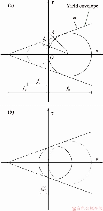
Figure 1 Yield envelope with tensile strength (a), zero tensile strength envelope (b)
Figure 2 represents a homogeneous soil slope model subjected to the pseudo-static seismic forces at the verge of failure. The inclination of the slope is described by angle b; the height of the slope is defined as H; and the soil is characterized by internal friction angle ¦Х, cohesion c, and unit soil weight ¦Г. Using the pseudo-static approach can first obtain the yield acceleration and the corresponding critical slip surface. The sliding body BDEC rotates about the center O along the curve DEC passing through the toe of this slope. The log-spiral EC is expressed as
 (4)
(4)
where r0 is the distance between center O and point A; ¦И0 is the angle between line OA and a horizontal line; ¦Иh is the angle between OC and horizontal line.
The curve DE is assumed as the slip surface where the tensile strength works. A modified log-spiral governed by dilatancy angles is used here to define the curve DE:
 (5)
(5)
where rm is the distance between center O and point D; ¦Иm is the angle between line OD and a horizontal line; ¦Иtc is the angle between OE and horizontal line; ¦Д is the dilatancy angle. The linear distribution form of ¦Д is proved to be conservative in MichalowskiЎЇs research [18]. The distribution form of ¦Д is postulated:
 (6)
(6)
Based on the UB theorem, equating the rate of work done by the external forces (i.e., soil gravity weight and seismic forces) to the rate of the energy dissipation along the slip surface can yield the energy balance
 (7)
(7)
where Wg is the rate of work done by soil weight; Ws is the rate of work done by the pseudo-static seismic load which defined by seismic coefficient k; D is the rate of internal energy dissipation for the sliding body BDEC. The work rate Wg can be calculated as the work rate of fictitious block ABC minus the work rates of the block.
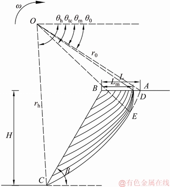
Figure 2 Collapse mechanism with reduced tensile strength
 (8)
(8)
where Wg1, Wg2, Wg3, Wg4, Wg5, Wg6 are the rates of work done by the soil weight of OCA, AOB, BOC, OEA, AOD, DOE, respectively; fw is the function coefficient of ¦В, ¦И0, ¦Иm, ¦Иtc ¦Иh; ¦Ш is angular velocity. Similarly, the rate of work done by seismic forces S can be written as
 (9)
(9)
where Ws1, Ws2, Ws3Ј¬ Ws4, Ws5, Ws6 are the rates of work done by the seismic forces on OCA, AOB, BOC, OEA, AOD, DOE respectively; fs is the function coefficient of ¦В, ¦И0, ¦Иm, ¦Иtc ¦Иh. In terms of the principal strain rates and introducing dissipation work done by tensile strength the dissipation within the slip surface can be expressed as
 (10)
(10)
where fd is the function coefficient of ¦Иtc, ¦Иh, ¦Х, fdc is the function coefficient of ¦Иtc, ¦Иm, ¦Х. The detailed expressions of fw, fs and fd, fdc are given in Appendix.
Substituting Eqs. (8)-(10) into Eq. (7) can obtain the seismic acceleration coefficient k as
 (11)
(11)
The upper bound of the yield acceleration ky is determined through the search for the minimum of k using Eq. (6), and the most critical slip surface is also obtained. After determining ky, the derived sliding body ABC is discretized into n blocks and each block is subjected to the same earthquake load at the same time. For arbitrarily nested block i, the corresponding slip surface (AC)i starts from point Ai and exits the slope face on point Ci. To avoid overlapping blocks, this procedure assumes that point Ai is in the front of the beginning point of the adjacent slip surface which is below the block i and point Ci is above the exiting point of that block. Repeating Eq. (6) can obtain the yield accelerations and geometry of rest nested blocks. In this study, all the mentioned variables with subscript i are corresponding to the block i.
The relative displacement of an arbitrary block i can be evaluated by combining the corresponding yield acceleration kyi and the input of acceleration-time history ki(t) that is computed through dynamic analysis corresponding to the given block, following the decoupled theorem. This process is presented as follows.
In the arbitrary block i, the movement triggered by seismic forces is assumed as rotational collapse. Hence, an additional work rate of the
rotation of the sliding body  will appear as a term in the right-hand side of Eq. (7).
 (12)
(12)
where  is the rotation acceleration; Gi is the weight of the rotation block; li is the distance from center Oi to the gravity center of the rotation block; g is the constant of gravity acceleration. The detailed expressions of Gi, li are given in Appendix. The rotation acceleration-time history is solved as
 (13)
(13)
In terms of Newmark theorem, the rotation velocity increases as long as ki(t) exceeds kyi and reaches its maximum when ki(t) falls down again to kyi. When ki(t) drops down to some valve below kyi, the block slows down and ceases. Double integrating over time interval with triangle transform, the horizontal relative displacement uxi which occurs at point Ci can be calculated.
 (14)
(14)
The total horizontal displacement of each nested block is then integrated for a given time increment, starting with the basal region and sequentially proceeding towards the crest (see Figure 2).
 (15)
(15)
Furthermore, yield accelerations of the upper nested blocks increase with the height increase. Therefore, the upper regions may not encounter yield and their displacement is solely a result of displacement of underlying failures.
3 Application and discussion
A slope model is considered here to investigate the influences of the tensile strength cut-off on post-earthquake slope profile. The model is consisted of a uniform soil characterized by ¦Г=20 kN/m3, ¦Х=30Ўг and c=20 kPa. The tensile strength fraction ¦О is assigned values of 0, 0.2, 0.5, to describe the tensile strength. The critical slip surfaces of these case are performed through the aforementioned method and are obtained, as shown in Figure 3(a). It is obvious that the slip surface starts closer to the crest with the decrease of the reduction fraction. The slip surface for this slope with traditional MC criterion is also illustrated and deeper than those with tension cut-off. Based on the NNM, these models are discretized into blocks along with the height. The nested blocks of the slopes are given for ¦О=0.5, as shown in Figure 3(b).
Figure 4 illustrates the yield acceleration along with the height for various reduction fraction coefficients. It can be seen that the yield acceleration increases with the increasing tensile strength fraction ¦О. As expected, the soil tensile strength is benefit to slope safety. The slope is subjected to seismic inputs of the 1999 Chi-Chi Earthquake in Taiwan, China (M=7.52, Station TCU072-000, t=66 s, Ўчt=0.005 s, the vertical acceleration is neglected) scaled to the maximum horizontal acceleration of 0.3g, 0.4g and 0.5g, as shown in Figure 5.

Figure 3 Slope shape and slip surfaces (a) and nested blocks of slope (¦О=0.5) (b)

Figure 4 Yield acceleration profile for example with various tensile strength fraction ¦О

Figure 5 Chi-Chi earthquake record
Based on NNM, 10 evenly-spaced nested blocks are adopted to estimate of the post- earthquake displacement for each model. Using the yield curve and the acceleration-time history calculates the horizontal relative displacement of the series of nested blocks. Integrating the relative displacement of each block from toe to crest calculates the horizontal displacement profile, as shown in Figure 6. Comparing with the traditional MC yield criterion, the involved tensile strength cut-off can increase the slope displacement. The effect of tensile strength becomes more significant as the acceleration PGA increases. Furthermore, the maximum displacement gradually moves to the upper part of the slope with PGA increasing and the reducing tensile strength fraction. The deformed shapes of the seismic slope are illustrated in Figure 7. Compared to the initial shape of the slope, the deformation for PGA=0.3g is small and can be neglected. In the case of PGA=0.3g, the displacements increase with the reduction of tensile strength. There are minor differences between the results for ¦О=0.5 and M-C. The differences are more significant as the PGA increases. As defined by HUANG et al [22], displacement ratio of the total displacement to slope height, dH/H is used here and then dH/H is less than 2% for 0.3g. As the maximum acceleration increases, the displacement ratio obviously increases, typically 15% for PGA=0.5g and ¦О=0.0.
To further investigate the influences of the earthquake records, four selected earthquake records are considered here. These records are from Northbridge earthquake, Imperial Valley earthquake, Kobe earthquake, Chi-Chi earthquake, and their PGA are all scaled to 0.4g, as shown in Figure 8.

Figure 6 Permanent displacement profiles for seismic slopes with tension cut-off
The selected earthquakes have different mean periods Tm. Through the NNM, the post-earthquake profile of the example is calculated using the four earthquakes, respectively. Figure 9 illustrates the maximum displacement in the time history using the MC criterion with tension cut-off ¦О=0, 0.2, 0.5 and without the cut-off. The displacement for tensile strength fraction ¦О=0 is the largest one. Using the traditional MC criterion can underestimate the displacement. In addition, the total displacements are given along the elevation of the slope height, as shown in Figure 10. It can be found that the total displacements obviously increase with the increasing mean period of the earthquake, especially for zero tension cut-off. Typically, the corresponding obtained total displacements for Kobe earthquake are two times larger than that of Northbridge earthquake. For the example subjected to the different seismic excitations, the location of the largest displacement keeps in the same elevation.

Figure 7 Initial and deformed slope profiles for seismic slopes with tension cut-off

Figure 8 Input motions:

Figure 9 Displacement-time history:
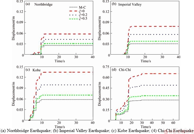
Figure 10 Horizontal displacement profiles:
4 Conclusions
This study introduces the tensile strength cut-off in the traditional MC criterion to extend NNM for calculating the post-earthquake profile of slope. Based on the extended NNM, a kinematic approach of limit analysis is carried out to determine the seismic displacement using the log-spiral failure surface. An example is given here to demonstrate the influence of the tension cut-off on the post-earthquake profile. Neglecting the tensile strength cut-off can underestimate the permanent displacement of the seismic slopes, typically 50% for slopes with zero tensile strength. The underestimation is more significant as the peak acceleration and the mean period increase. The maximum displacement of the slope is closer to the slope crest with the decreasing tensile strength fraction ¦О. However, the elevation of the maximum displacement is not dependent on the input ground motion. The present analysis is limited to the two-dimensional problem. Extrapolating the application of the method to the three-dimensional problem are straightforward. In addition, the interaction between blocks and the topographic effect are not included in this study and would be further investigated in the future work.
Notation
fc
Uniaxial compressive strength
ft
Uniaxial tensile strength
f3t
Triaxial tensile strength
¦Д
Dilatancy angle
¦Х
Internal friction angle
c
Cohesion
¦О
Reduction fraction
d
Work dissipation
W
Rate of work
[¦Ф]
Velocity discontinuity vector
H
Slope height
L
Distance between crest and slip surface
Lm
Distance between crest and slip surface
r
Radial coordinate in the polar system
¦И
Angular coordinate in polar system
¦Ш
Angular velocity
¦Г
Unit weight
¦В
Slope inclination angle
Appendix


References
[1] TERZAGHI K. Mechanisms of landslides [M]// Engineering Geology (Berkey) Volume. Geological Society of America, 1950.
[2] SARMA S K, BHAVE M V. Critical acceleration versus static factor of safety in stability analysis of earth dams and embankments [J]. Geotechnique, 1974, 24(4): 661-665.
[3] NEWMARK N M. Effects of Earthquakes on dams and embankments [J]. GЁ¦otechnique, 1965, 15(2): 139-160.
[4] SARMA S K. Seismic stability of earth dams and embankments [J]. GЁ¦otechnique, 1975, 25(4): 743-761.
[5] SEED H B, IDRISS I M, LEE K L, MAKDISI F L. Dynamic analysis of the slide in the lower san fernando dam during the earthquake of February 9, 1971 [J]. Journal of Geotechnical and Geoenvironmental Engineering, 1975, 101(9): 889-911.
[6] LEE K L. Seismic permanent deformations in earth dams, Report No. UCLA-ENG-7497 [R]. School of Engineering and Applied Science, University of California at Los Angeles, 1974.
[7] SERFF N, SEED H B, MAKDISI F I, CHANG C Y. Earthquake-induced deformations of earth dams. Report EERC 76-4 [R]. Earthquake Engineering Research Center, University of California, Berkeley, 1976.
[8] CHUGH A K, STARK T D. Permanent seismic deformation analysis of a landslide [J]. Landslides, 2006, 3(1): 2-12.
[9] SEED H B, GOODMAN R E. Earthquake stability of slopes of cohesionless soils [J]. Journal of Soil Mechanics & Foundations Div, 1964, 90(5): 43-68.
[10] WARTMAN J, SEED R B, BRAY J D. Shaking table modeling of seismically induced deformations in slopes [J]. Journal of Geotechnical and Geoenvironmental Engineering, 2005, 131(5): 610-622.
[11] KUTTER B L, JAMES R G. Dynamic centrifuge model tests on clay embankments [J]. GЁ¦otechnique, 1989, 39(1): 91-106.
[12] LING H I, LESHCHINSKY D. Seismic performance of simple slopes [J]. Soils and Foundations, 1995, 35(2): 85-94.
[13] YOU L, MICHALOWSKI R L. Displacement charts for slopes subjected to seismic loads [J]. Computers and Geotechnics, 1999, 25(1): 45-55.
[14] LESHCHINSKY B. Nested Newmark model to calculate the post-earthquake profile of slopes [J]. Engineering Geology, 2018, 233(1): 139-145.
[15] YANG X L, HUANG F. Slope stability analysis considering joined influences of nonlinearity and dilation [J]. Journal of Central South University of Technology, 2009, 16(2): 292-296.
[16] ZHANG D B, JIANG Y, YANG X L. Estimation of 3D active earth pressure under nonlinear strength condition [J]. Geomechanics and Engineering, 2019, 17(6): 515-525.
[17] UTILI S, ABD A H. On the stability of fissured slopes subject to seismic action [J]. International Journal for Numerical and Analytical Methods in Geomechanics, 2016, 40(5): 785-806.
[18] MICHALOWSKI R L. Stability of intact slopes with tensile strength cut-off [J]. GЁ¦otechnique, 2017, 67(8): 720-727.
[19] DRUCKER D C, PRAGER W. Soil mechanics and plastic analysis or limit design [J]. Quarterly of Applied Mathematics, 1952, 10(2): 157-165.
[20] BAKER R, GARBER M. Theoretical analysis of the stability of slopes [J]. GЁ¦otechnique, 1978, 28(4): 395-411.
[21] LESHCHINSKY D, BAKER R, SILVER M L. Three dimensional analysis of slope stability [J]. International Journal for Numerical and Analytical Methods in Geomechanics, 1985, 9(3): 199-223.
[22] HUANG C, WU S H, WU H J. Seismic displacement criterion for soil retaining walls based on soil strength mobilization [J]. Journal of Geotechnical and Geoenvironmental Engineering, 2009, 135(1): 74-83.
(Edited by HE Yun-bin)
ЦРОДµј¶Б
»щУЪNNMДЈРНїјВЗНБМеАЙмЅШ¶ПµД±ЯЖВµШХрУАѕГО»ТЖјЖЛг·Ѕ·Ё
ХЄТЄЈєЗ¶МЧКЅNewmarkДЈРН(NNM)КЗТ»ЦЦїјВЗНБМејфЗРФЛ¶ЇМШРФµДµШХр±ЯЖВ±дРОјЖЛгДЈРНЈ¬ёГДЈРНОЮ·ЁїјВЗ±ЯЖВФЪµШХрЧчУГПВНБМеіцПЦАУ¦Б¦Зь·юМШРФЎЈ±ѕОДЅ«НБМеАЙмЅШ¶ПМШРФїјВЗµЅБЛNNMДЈРНЦРЈ¬ІЙУГј«ПЮ·ЦОцЙППЮ·ЁЅЁБўБЛ±ЯЖВµШХрУАѕГО»ТЖјЖЛг·Ѕ·ЁЎЈНЁ№э¶ФАЙмЅШ¶ПІОКэУлµШХрІОКэµДГфёРРФ·ЦОцЈ¬·ўПЦєцВФНБМеµДАЙмЅШ¶П»бµН№А±ЯЖВµШХрУАѕГО»ТЖЎЈЛжЧЕµШХр·еЦµјУЛЩ¶ИµДФцґуЈ¬АЙмЅШ¶П¶Ф±ЯЖВ±дРОµДУ°ПмЅ«ёьјУПФЦшЈ»ЛжЧЕї№АЗї¶ИµДјхРЎЈ¬µШХр±ЯЖВµДЧоґу±дРОО»ЦГЦрІЅПтЖВ¶ҐїїЅьЎЈ
№ШјьґКЈє±ЯЖВЈ»ј«ПЮ·ЦОцЈ»µШХрЈ»УАѕГО»ТЖЈ»NewmarkЈ»ї№АЗї¶И
Foundation item: Projects(41630638, 51878248) supported by the National Natural Science Foundation of China
Received date: 2019-04-22; Accepted date: 2019-05-06
Corresponding author: ZHANG Fei, PhD, Associate Professor; Tel: +86-13675110680; E-mail: feizhang@hhu.edu.cn; ORCID: 0000- 0001-5517-7725

